EP2006633A2 - Selbstnachführendes Laserinterferometer und Verfahren zur seiner Rücksetzung - Google Patents
Selbstnachführendes Laserinterferometer und Verfahren zur seiner Rücksetzung Download PDFInfo
- Publication number
- EP2006633A2 EP2006633A2 EP08011083A EP08011083A EP2006633A2 EP 2006633 A2 EP2006633 A2 EP 2006633A2 EP 08011083 A EP08011083 A EP 08011083A EP 08011083 A EP08011083 A EP 08011083A EP 2006633 A2 EP2006633 A2 EP 2006633A2
- Authority
- EP
- European Patent Office
- Prior art keywords
- light
- retroreflector
- axis
- fan
- tracking
- Prior art date
- Legal status (The legal status is an assumption and is not a legal conclusion. Google has not performed a legal analysis and makes no representation as to the accuracy of the status listed.)
- Granted
Links
Images



Classifications
-
- G—PHYSICS
- G01—MEASURING; TESTING
- G01C—MEASURING DISTANCES, LEVELS OR BEARINGS; SURVEYING; NAVIGATION; GYROSCOPIC INSTRUMENTS; PHOTOGRAMMETRY OR VIDEOGRAMMETRY
- G01C15/00—Surveying instruments or accessories not provided for in groups G01C1/00 - G01C13/00
- G01C15/002—Active optical surveying means
-
- G—PHYSICS
- G01—MEASURING; TESTING
- G01B—MEASURING LENGTH, THICKNESS OR SIMILAR LINEAR DIMENSIONS; MEASURING ANGLES; MEASURING AREAS; MEASURING IRREGULARITIES OF SURFACES OR CONTOURS
- G01B2290/00—Aspects of interferometers not specifically covered by any group under G01B9/02
- G01B2290/15—Cat eye, i.e. reflection always parallel to incoming beam
-
- G—PHYSICS
- G01—MEASURING; TESTING
- G01S—RADIO DIRECTION-FINDING; RADIO NAVIGATION; DETERMINING DISTANCE OR VELOCITY BY USE OF RADIO WAVES; LOCATING OR PRESENCE-DETECTING BY USE OF THE REFLECTION OR RERADIATION OF RADIO WAVES; ANALOGOUS ARRANGEMENTS USING OTHER WAVES
- G01S17/00—Systems using the reflection or reradiation of electromagnetic waves other than radio waves, e.g. lidar systems
- G01S17/66—Tracking systems using electromagnetic waves other than radio waves
Definitions
- the present invention relates to a tracking type laser interferometer and a method for resetting the same, and in particular, to a tracking type laser interferometer and a method for resetting the same, which are preferable for a tracking type laser interferometer that detects displacement of a retroreflector being an object to be measured by utilizing interference of a laser beam, which is irradiated onto the retroreflector and is reflected by the retroreflector in the returning direction, and carries out tracking by means of a two-axis turning mechanism using a change in the position of the optical axis of the laser beam, and are capable of automatically resetting the laser interferometer to a tracking state even if the tracking is made impossible due to interruption of the laser beam, etc., or are capable of automating initial adjustment work when measurement is commenced.
- Tracking type laser interferometers that were disclosed by Japanese Published Unexamined Patent Application No. 2007-057522 (Patent Document 1), Japanese Patent No. 2603429 (Patent Document 2), and United States Patent No. 6147748 (Patent Document 3) are available as a tracking type laser interferometer that measures the displacement and position of a moving body with high accuracy while tracking the moving body. Representatively, a description is given of a case where a homodyne Michelson type laser interferometer is employed that is described in Patent Document 1, using FIG. 1 and FIG.2 .
- FIG. 1 is a perspective view showing the entire configuration of a conventional tracking type laser interferometer
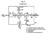
- FIG. 2 is a brief configurational view showing the portion of an interferometer, respectively.
- a tracking type laser interferometer includes a light source portion 100, a main body portion 200, a retroreflector 300, a circuit portion 400 and a personal computer (PC) 500.
- PC personal computer
- the light source portion 100 includes a frequency stabilized He-Ne laser light source 110, a lens 120 and an optical fiber 130.
- the main body portion 200 includes a measurement portion 220, a two-axis turning mechanism 240, a reference sphere 260, and a base 280.
- the two-axis turning mechanism 240 is fixed on the base 280, and the measurement portion 220 is fixed on the two-axis turning mechanism 240.
- the reference sphere 260 is fixed on the base 280, and the center of the reference sphere 260 is made coincident with the center of turning of the two-axis turning mechanism 240.
- the measurement portion 220 includes a displacement gauge 221 and an interferometer 230.
- the interferometer 230 includes, as shown in FIG. 2 , a collimator lens 231, a polarization beam splitter (PBS) 232, ⁇ /4 plates 233, 236, a planar mirror 234, a non-polarization beam splitter (NPBS) 235, a polarization plate 237, a two-dimensional PSD (Position Sensing Detector) or a quadruplicate divisional photo diode (QPD) 238, and a detector 239.
- the two-axis turning mechanism 240 includes a carriage 242, an elevation angle motor 244, and an azimuth angle motor 246.
- the circuit portion 400 includes signal processing circuits 410 through 430 and motor drive circuits 440 and 450.
- a laser beam incident into the interferometer 230 is emitted from the frequency stabilized He-Ne laser light source 110, and is made incident into the interferometer 230 through the lens 120 and the optical fiber 130.
- a laser beam incident into the interferometer 230 is split into two by the PBS 232, one of which is used as reference light for measurement of length, and the other of which is emitted to the retroreflector 300.
- the laser beam 102 emitted to the retroreflector 300 is again made incident into the interferometer 230 having the ⁇ /4 plate 236 after being reflected by the retroreflector 300.
- the laser beam 102 that is again made incident into the interferometer 230 is split into two by means of the NPBS 235, one of which interferes with the reference light as measurement light.
- the detector 239 detects a change in intensity of the interference light, and the change in intensity is processed by the signal processing circuit 410, wherein displacement ⁇ L1 between the retroreflector 300 and the interferometer 230 is measured by using the PC 500.
- the displacement gauge 221 is an electrostatic capacitance type displacement gauge or an eddy current type displacement gauge, which detects displacement with respect to the reference sphere 260, and the displacement is processed by the signal processing circuit 420, wherein the displacement ⁇ L2 between the reference sphere 260 and the displacement gauge 221 is measured by using the PC 500.
- the QPD 238 can measure the ⁇ Tr in terms of dividing the component in two directions orthogonal to each other. For example, as shown in FIG.
- the QPD 238 can detect the X-axis direction component ⁇ TrX and the Y-axis direction component ⁇ TrY with respect to ⁇ Tr.
- signals responsive to the ⁇ TrX and ⁇ TrY are brought into the PC 500 via the signal processing circuit 430, and control signals responsive to the values of ⁇ TrX and ⁇ TrY are given to the motor drive circuits 440 and 450.
- the motor drive circuits 440 and 450 drive the elevation angle motor 244 and the azimuth angle motor 246 and rotates the carriage 242 in the elevation angle direction and the azimuth angle direction, wherein the center position of the retroreflector 300 and the optical axis of the laser emitted from the interferometer 230 are controlled so as to become coincident with each other in order to carry out tracking.
- Patent Document 1 wherein it is a common problem to Patent Documents 2 and 3.
- the present invention was developed in order to solve the above-described conventional problems, and it is therefore an obj ect of the invention to provide a tracking type laser interferometer and a method for resetting the same, which is capable of automatically resetting tracking when tracking becomes impossible due to a reason such as interruption of the laser light, etc., or automating initial adjustment work when commencing measurement, in a tracking type laser interferometer.
- the present invention solves the object by providing a tracking type laser interferometer with a light irradiator that emits a fan-shaped laser light that is fan-shaped including the optical axis of the laser beam, and is interlocked with turning movements of the two-axis turning mechanism around an axis orthogonal to the center axis of the fan shape, and a light receptor that has a specific positional relationship with the retroreflector or the light irradiator and receives the fan-shaped laser light, in the tracking type laser interferometer that detects displacement of a retroreflector by utilizing interference of a laser beam irradiated onto a retroreflector being an object to be measured and reflected by the corresponding retroreflector in the returning direction, and carries out tracking by means of the two-axis turning mechanism using a change in the position of the optical axis of the laser beam.
- the present invention also provides a method for resetting a tracking type laser interferometer that detects displacement of a retroreflector being an object to be measured by utilizing interference of a laser beam, which is irradiated onto a retroreflector and is reflected by the corresponding retroreflector in the returning direction, and carries out tracking by means of the two-axis turning mechanism using a change in the position of the optical axis of the laser beam, wherein the method includes the steps of: emitting a fan-shaped laser light having a fan shape on a plane including the optical axis of the laser beam from a light irradiator secured on the two-axis turning mechanism when the tracking control is not carried out; executing a turning movement centering around the axis orthogonal to the fan-shaped center axis of the two-axis turning mechanism; detecting the fan-shaped laser light in a light receptor having a specific positional relationship with the retroreflector or the light irradiator, obtaining the first turning angle by which tracking control
- the above-described light receptor may be secured at the retroreflector.
- the light receptor may be provided in the two-axis turning mechanism.
- the light receptor may be fixed so that the optical axis when the fan-shaped laser light is emitted to the retroreflector and the optical axis when the laser light is reflected by the retroreflector and is received by the light receptor are common to each other at least on a part of the optical path.
- the light irradiator and the light detector including the light receptor may be provided in the two-axis turning mechanism.
- the present invention by providing a light irradiator and a light receptor to the configuration of the conventional laser interferometer, it becomes possible to automatically reset tracking without any manual work when the tracking is disabled due to a reason such as interruption of laser light. In addition, it is possible to automatically carry out initial adjustment work when measurement is commenced.
- FIG. 3 is a perspective view showing the entire configuration of a tracking type laser interferometer according to the present embodiment
- FIG. 4 is a brief sectional view of the main body portion of a tracking type laser interferometer, which shows the position of the same interferometer.
- the present embodiment is provided with a light source portion 100, a main body portion 200, a retroreflector 300, a circuit portion 400, and a PC 500, which are main components of a conventional homodyne tracking type laser interferometer, and is further provided with a light irradiator 600, and a reflector 610 (not illustrated), which are characteristic components of the present embodiment, in the main body portion 200, and further includes a light receptor 620, a power supply circuit 640, and a signal processing circuit 650.
- a description is omitted of the conventional components, a description is given of the functions of the above-described elements and changes in the conventional components.
- the light irradiator 600 is attached to the substrate side of the elevation angle motor 245 above the azimuth angle motor 247 that is a component of the two-axis turning mechanism 240 as shown in FIG. 3 .
- the light irradiator 600 is, for example, a line laser, and may have such a feature that emitted laser light is widened to be fan-shaped in the Y-axis direction.
- the light irradiator 600 is attached to the substrate side of the elevation angle motor 245 so that the fan-shaped laser light 602 includes the optical axis of the laser beam 102 emitted from the main body portion 200, the light irradiator 600 is interlocked with turning of the azimuth angle motor 247, that is, is interlocked with turning movements around the Y-axis that is an axis orthogonal to the center axis of a fan shape of the fan-shaped laser light 602. Also, although the outlines of the azimuth angle motor 247 and the elevation angle motor 245 are different from the conventional outlines shown in FIG. 1 , the functions and mutual arrangement are substantially identical to those of the prior art.
- the reflector 610 has a function of reflecting a laser beam 102 emitted along the Y-axis from the interferometer 230 fixed at, for example, the base 281, and of emitting the same from the main body portion 200 toward the retroreflector 300.
- a reflection mirror having high flatness and a prism may be used as the reflector 610.
- the reflector 610 is fixed on the carriage 243 so that the reflection surface of the reflector 610 comes to the center of the turning axis of elevation angle motor 245 and the azimuth angle motor 247, which exist on the Y-axis.
- the reference sphere 260 shown in FIG. 1 is not provided in the present embodiment. Therefore, since the two-axis turning mechanism 240 does not incorporate the interferometer 230 and the displacement gauge 221, the two-axis turning mechanism 240 can be further downsized, wherein highly accurate control is enabled. Further, since no reference sphere 260 is used, the main body portion 200 can be further downsized.
- the light receptor 620 has a light-receiving element.
- the light-receiving element has high sensitivity characteristics to the frequency (wavelength) of the fan-shaped laser light 620 of the light irradiator 600.
- the light irradiator 600 is a semiconductor laser
- a photo diode (PD) having high sensitivity with respect to the semiconductor laser is used as the light-receiving element, wherein the azimuth angle may be determined even if the main body portion 200 is far from the retroreflector 300.
- PD photo diode
- the light-receiving body 620 is fixed and linked by means of jigs so that it becomes a specific positional relationship with the retroreflector 300, for example, so that it becomes the same azimuth angle when being observed from the main body portion 200, and if the retroreflector 300 moves, the light receptor 620 may also move. That is, at the stage when the fan-shaped laser light 602 of the light irradiator 600 is received, it is possible to quickly obtain the azimuth angle of the two-axis turning mechanism 200.
- the power supply circuit 640 is connected to the light irradiator 600, and has a function to control emission and stop of the fan-shaped laser light 602 of the light irradiator 600 by a signal from the PC 500. Therefore, it is possible to automatically control emission and stop of the fan-shaped laser light 602 by a signal from the PC 500.
- the signal processing circuit 650 is connected to the light receptor 620, and has a function to transmit a signal responsive to the intensity of received light to the PC 500 when it receives the fan-shaped laser light 602 of the light irradiator 600. Therefore, using the relationship between the drive signal to the motor drive circuit 440 and the receiving light intensity, it is possible to obtain the azimuth angle at high accuracy in the PC 500.
- the light amount detected by the QPD 238 in the interferometer 230 becomes zero (0). Then, the QPD 238 transmits a signal of light quantity 0 to the PC 500 via the signal processing circuit 430.
- the PC 500 judges based on the signal that the laser beam 102 from the interferometer 230 is interrupted, the PC 500 stops tracking control of the tracking type laser interferometer by the two-axis turning mechanism 240 by means of the motor drive circuits 440 and 450. Simultaneously, measurement of displacement by output of the detector 239 is discontinued.
- the PC 500 transmits a signal to the power supply circuit 640, the power supply of the light irradiator 600 is turned on, and a fan-shaped laser beam 602 is emitted.
- the PC 500 transmits a signal to the motor drive circuit 440, and causes the azimuth angle motor 247 to turn the azimuth angle.
- the PC 500 commences measurement of signals transmitted from the light receptor 620 via the signal processing circuit 650. And, if the stop condition at which the light amount exceeds a threshold value defined in advance with respect to the light amount detected by the light receptor 620 is met, the azimuth angle is stopped and maintained at the position (the first turning angle) of a turning angle that satisfies the stop condition. And, the PC 500 transmits a signal to the power supply circuit 640 and turns off the power supply of the light irradiator 600. At the same time, the PC 500 discontinues measurement of the signals from the light receptor 620.
- the PC 500 transmits a signal to the motor drive circuit 450, and causes the elevation angle to be turned by the elevation angle motor 245. Then, the elevation angle is stopped and maintained at the position (the second turning angle) of a turning angle at which the QPD 238 in the interferometer 230 can detect the light amount. In this state, the light amount is detected by the QPD 238 by a laser beam 102 emitted from the main body portion 200 and reflected by the retroreflector 300, wherein by measuring the tracking errors ⁇ TrX and ⁇ TrY, it becomes possible to re-start tracking control of a normal tracking type laser interferometer.
- the tracking type laser interferometer can be controlled and reset by respective input signals on the PC 500, the tracking type laser interferometer can be fully automatically reset without depending on any manual operation when no tracking becomes available due to a reason such as interruption of the laser beam 102 emitted from the main body portion 200. Therefore, initial adjustment work when commencing measurement, which causes similar situations, can be automated. Accordingly, since environmental fluctuations due to intervention of a human being can be prevented, further accurate and stable measurement can be carried out.
- the above-described stop condition may be used as the maximum value of light amount to be detected.
- the stop condition may be a condition for turning and moving the laser beam to the angular range where tracking control is made possible.
- the light receptor 620 may include a lens.
- a lens By utilizing the light condensing action of a lens, it becomes possible for the light-receiving element to obtain a sufficient light amount even if the retroreflector 300 is far from the main body portion 200.
- FIG. 5 is a perspective view showing the entire configuration of a tracking type laser interferometer according to the present embodiment
- FIG. 6 is a brief configurational view showing a light detector of the same interferometer.
- the present embodiment is provided with a light source portion 100, a main body portion 200, a retroreflector 300, a circuit portion 400, and a PC 500, which are main components of a conventional homodyne tracking type laser interferometer, and is further provided with a light detector 660, and a reflector 610 (not illustrated), which are characteristic components of the present embodiment, in themainbodyportion 200, and further includes a power supply circuit 640 and a signal processing circuit 650. That is, in the present embodiment, the light detector 660 is provided instead of the light irradiator 600 and the light receptor 620, which are described in Embodiment 1.
- the light detector 660 is mounted at the substrate side of the elevation angle motor 245 above the azimuth angle motor 247, which are components of the two-axis turning mechanism which is identical to that of Embodiment 1. That is, the fan-shaped laser light 602 emitted from the light detector 660 is interlocked with turning of the azimuth angle motor 247. And, the light detector 660 includes a light irradiator 601 and a light receptor 630 as shown in FIG. 6 .
- the light receptor 630 has, for example, a beam splitter (BS) 632, a lens 634 and a light-receiving element 636.
- the light irradiator 601 differs from the light irradiator 600 only in that light is emitted via the BS 632. In other points, the light irradiator 601 is substantially identical to the light irradiator 600 according to Embodiment 1. And, since the positional relationship between the fan-shaped laser light 602 and the main body portion 200 is as described in Embodiment 1, a description thereof is omitted.
- the function of the light receptor 630 is similar to the light receptor 620 described in Embodiment 1. However, since the optical axis in the emission direction of the fan-shaped laser light 602 to the retroreflector 300 and that in the incident direction of light reflected by the retroreflector 300 are made the same up to the main body portion 200, the light receptor 630 uses the BS 632 as a component. Also, in comparison with Embodiment 1, since attenuation of the fan-shaped laser light 602 is great, the lens 634 is also used as a component in order to gain the amount of light received by the light-receiving element 636.
- the fan-shaped laser light 602 As the fan-shaped laser light 602 is emitted from the light irradiator 601, the fan-shaped laser light 602 passes through the BS 632 of the light receptor 630 and is reflected by the retroreflector 300. The reflected and returned fan-shaped laser light 602 is reflected by the BS 632, and is condensed by the lens 634, and is detected by the light-receiving element 636.
- the optical axis of the light irradiator 601 and the optical axis of the light receptor 630 are commonly used to the BS 632, the resetting operation of the tracking type laser interferometer according to the present invention is enabled if a constant positional relationship between the light irradiator 601 and the light receptor 630 is taken into consideration even if the light irradiator 601 and the light receptor 630 are provided at far positions on the two-axis turning mechanism. Such a configuration is included in the present invention.
- the fan shape of the fan-shaped laser light 602 is turned centering around the Y-axis so as to be diffused on the YZ plane centering around the Z-axis.
- the fan shape thereof is turned centering around the X-axis by utilizing the fan shape diffused on the XZ plane centering around the Z-axis. That is, in the case of the above-described embodiments, when carrying out automatic resetting operation, the light irradiator or the light receptor is mounted on the carriage that turns by the elevation angle motor, the elevation angle motor is first turned with the azimuth angle motor not first turned, and next the azimuth angle motor is turned.
- the line laser used for the light irradiator is a semiconductor laser, etc., it may be another laser, for example, a solid-state laser or a gas laser, etc. Also, the frequency thereof may not be limited.
- the generation method may not be limited in the present invention.
- the light-receiving element used for the light receptor is not limited to the PD.
- a line type or an area type optical position detection element (PSD) may be included in the present invention.
- the interferometer is a tracking type laser interferometer
- the present invention can be achieved by incorporating the light irradiators 600, 601 and the light receptor 620,630, etc. Therefore, it is clear that the interferometer is not limited to the homodyne tracking type laser interferometer, for example, the present invention may be applicable to a tracking type laser interferometer including a heterodyne tracking type laser interferometer.
Landscapes
- Physics & Mathematics (AREA)
- Engineering & Computer Science (AREA)
- General Physics & Mathematics (AREA)
- Radar, Positioning & Navigation (AREA)
- Remote Sensing (AREA)
- Length Measuring Devices By Optical Means (AREA)
- Instruments For Measurement Of Length By Optical Means (AREA)
- Optical Radar Systems And Details Thereof (AREA)
Applications Claiming Priority (1)
| Application Number | Priority Date | Filing Date | Title |
|---|---|---|---|
| JP2007162295A JP5244339B2 (ja) | 2007-06-20 | 2007-06-20 | 追尾式レーザ干渉計および追尾式レーザ干渉計の復帰方法 |
Publications (3)
| Publication Number | Publication Date |
|---|---|
| EP2006633A2 true EP2006633A2 (de) | 2008-12-24 |
| EP2006633A3 EP2006633A3 (de) | 2009-01-14 |
| EP2006633B1 EP2006633B1 (de) | 2011-08-03 |
Family
ID=39720095
Family Applications (1)
| Application Number | Title | Priority Date | Filing Date |
|---|---|---|---|
| EP08011083A Ceased EP2006633B1 (de) | 2007-06-20 | 2008-06-18 | Selbstnachführendes Laserinterferometer und Verfahren zur seiner Rücksetzung |
Country Status (3)
| Country | Link |
|---|---|
| US (1) | US7872733B2 (de) |
| EP (1) | EP2006633B1 (de) |
| JP (1) | JP5244339B2 (de) |
Cited By (1)
| Publication number | Priority date | Publication date | Assignee | Title |
|---|---|---|---|---|
| DE102010002035B4 (de) | 2009-02-17 | 2019-10-17 | Mitutoyo Corp. | Nachführtyp-Laserinterferometer |
Families Citing this family (39)
| Publication number | Priority date | Publication date | Assignee | Title |
|---|---|---|---|---|
| JP2008203015A (ja) * | 2007-02-19 | 2008-09-04 | Mitsutoyo Corp | 光軸偏向型レーザ干渉計 |
| DE112009005524B3 (de) * | 2008-11-17 | 2018-01-25 | Faro Technologies, Inc. | Vorrichtung und Verfahren zum Messen von sechs Freiheitsgraden |
| US9482755B2 (en) | 2008-11-17 | 2016-11-01 | Faro Technologies, Inc. | Measurement system having air temperature compensation between a target and a laser tracker |
| US8467072B2 (en) | 2011-02-14 | 2013-06-18 | Faro Technologies, Inc. | Target apparatus and method of making a measurement with the target apparatus |
| JP5438988B2 (ja) * | 2009-02-17 | 2014-03-12 | 株式会社ミツトヨ | 測定システムおよび干渉計 |
| JP5624615B2 (ja) * | 2009-06-23 | 2014-11-12 | ライカ・ジオシステムズ・アクチェンゲゼルシャフトLeica Geosystems Ag | 追跡方法、および、レーザートラッカを有する測定システム |
| DE102009028068B4 (de) * | 2009-07-29 | 2023-05-25 | Dr. Johannes Heidenhain Gmbh | Positionsmessvorrichtung |
| US8659749B2 (en) | 2009-08-07 | 2014-02-25 | Faro Technologies, Inc. | Absolute distance meter with optical switch |
| DE102009040863A1 (de) * | 2009-09-10 | 2011-03-24 | Carl Zeiss Ag | Vorrichtung, Verfahren und Reflektoranordnung zur Positionsbestimmung |
| DE102009040837A1 (de) * | 2009-09-10 | 2011-03-17 | Carl Zeiss Ag | Vorrichtungen und Verfahren zur Positionsbestimmung und Oberflächenvermessung |
| JP5364519B2 (ja) * | 2009-09-18 | 2013-12-11 | 株式会社ミツトヨ | 追尾式レーザ干渉測長計 |
| US9772394B2 (en) | 2010-04-21 | 2017-09-26 | Faro Technologies, Inc. | Method and apparatus for following an operator and locking onto a retroreflector with a laser tracker |
| US9377885B2 (en) | 2010-04-21 | 2016-06-28 | Faro Technologies, Inc. | Method and apparatus for locking onto a retroreflector with a laser tracker |
| US9400170B2 (en) | 2010-04-21 | 2016-07-26 | Faro Technologies, Inc. | Automatic measurement of dimensional data within an acceptance region by a laser tracker |
| US8619265B2 (en) | 2011-03-14 | 2013-12-31 | Faro Technologies, Inc. | Automatic measurement of dimensional data with a laser tracker |
| RU2010124265A (ru) * | 2010-06-16 | 2011-12-27 | Алексей Владиславович Жданов (RU) | Способ и устройство определения направления начала движения |
| DE102010032407B3 (de) * | 2010-06-29 | 2011-12-15 | Bundesrepublik Deutschland, vertr. durch d. Bundesministerium f. Wirtschaft und Technologie, dieses vertreten durch d. Präsidenten d. Physikalisch-Technischen Bundesanstalt | Laser-Längenmesssystem |
| WO2012079875A1 (en) * | 2010-12-13 | 2012-06-21 | Paul Scherrer Institut | Tracking type laser interferometer for objects with rotational degrees of freedom |
| US8902408B2 (en) | 2011-02-14 | 2014-12-02 | Faro Technologies Inc. | Laser tracker used with six degree-of-freedom probe having separable spherical retroreflector |
| USD688577S1 (en) | 2012-02-21 | 2013-08-27 | Faro Technologies, Inc. | Laser tracker |
| US9686532B2 (en) | 2011-04-15 | 2017-06-20 | Faro Technologies, Inc. | System and method of acquiring three-dimensional coordinates using multiple coordinate measurement devices |
| US9482529B2 (en) | 2011-04-15 | 2016-11-01 | Faro Technologies, Inc. | Three-dimensional coordinate scanner and method of operation |
| US9164173B2 (en) | 2011-04-15 | 2015-10-20 | Faro Technologies, Inc. | Laser tracker that uses a fiber-optic coupler and an achromatic launch to align and collimate two wavelengths of light |
| US8537376B2 (en) | 2011-04-15 | 2013-09-17 | Faro Technologies, Inc. | Enhanced position detector in laser tracker |
| JP2013003124A (ja) * | 2011-06-22 | 2013-01-07 | Mitsutoyo Corp | 追尾式レーザ干渉計 |
| JP6099675B2 (ja) | 2012-01-27 | 2017-03-22 | ファロ テクノロジーズ インコーポレーテッド | バーコード識別による検査方法 |
| US9041914B2 (en) | 2013-03-15 | 2015-05-26 | Faro Technologies, Inc. | Three-dimensional coordinate scanner and method of operation |
| JP6104708B2 (ja) * | 2013-05-24 | 2017-03-29 | 株式会社ミツトヨ | 追尾式レーザ干渉計 |
| JP6227324B2 (ja) * | 2013-08-23 | 2017-11-08 | 株式会社トプコン | 測量機及び測量作業システム |
| US9395174B2 (en) | 2014-06-27 | 2016-07-19 | Faro Technologies, Inc. | Determining retroreflector orientation by optimizing spatial fit |
| JP6512917B2 (ja) * | 2015-04-20 | 2019-05-15 | 株式会社ミツトヨ | 追尾式レーザ干渉計および追尾式レーザ干渉計の復帰方法 |
| JP6539485B2 (ja) | 2015-04-21 | 2019-07-03 | 株式会社ミツトヨ | 追尾式レーザ干渉計を用いた測定システム、及びその復帰方法 |
| EP3199913B1 (de) * | 2016-01-28 | 2019-04-03 | Leica Geosystems AG | Vorrichtung zum automatischen auffinden eines beweglichen geodätischen zielobjekts |
| JP6799414B2 (ja) * | 2016-08-10 | 2020-12-16 | 株式会社ミツトヨ | 追尾式レーザ干渉計のフィードバックゲイン調整方法及び装置 |
| CN106595480B (zh) * | 2016-12-09 | 2019-03-22 | 北京交通大学 | 用于测量转轴六自由度几何误差的激光测量系统及方法 |
| JP7270477B2 (ja) * | 2019-06-17 | 2023-05-10 | 株式会社ミツトヨ | 測定装置 |
| JP7408303B2 (ja) * | 2019-06-18 | 2024-01-05 | 株式会社ミツトヨ | 測定装置 |
| CN115307579B (zh) * | 2022-08-25 | 2025-05-09 | 中国科学院微电子研究所 | 一种激光跟踪仪俯仰轴和方位轴的垂直度误差检测装置 |
| CN118640798B (zh) * | 2024-08-14 | 2024-11-19 | 中国测试技术研究院 | 一种减小激光跟踪仪测量误差的校准方法 |
Citations (3)
| Publication number | Priority date | Publication date | Assignee | Title |
|---|---|---|---|---|
| JP2603429B2 (ja) | 1993-10-25 | 1997-04-23 | 工業技術院長 | 追尾式レーザ干渉計 |
| US6147748A (en) | 1997-10-17 | 2000-11-14 | The Secretary Of State For Trade And Industry In Her Britannic Majesty's Government Of The United Kingdom Of Great Britain And Northern Ireland | Tracking system |
| JP2007057522A (ja) | 2005-07-26 | 2007-03-08 | Mitsutoyo Corp | 追尾式レーザ干渉計 |
Family Cites Families (10)
| Publication number | Priority date | Publication date | Assignee | Title |
|---|---|---|---|---|
| US4714339B2 (en) * | 1986-02-28 | 2000-05-23 | Us Commerce | Three and five axis laser tracking systems |
| JP2692778B2 (ja) * | 1994-01-31 | 1997-12-17 | 工業技術院長 | 高速追尾式レーザ干渉測長器 |
| JP2795613B2 (ja) * | 1994-06-07 | 1998-09-10 | 工業技術院長 | 移動体の位置及び姿勢の測定方法 |
| DE19733491B4 (de) * | 1997-08-01 | 2009-04-16 | Trimble Jena Gmbh | Verfahren zur Zielsuche für geodätische Geräte |
| JP4210792B2 (ja) * | 1999-06-15 | 2009-01-21 | 株式会社トプコン | 位置検出装置 |
| EP1329690A1 (de) * | 2002-01-22 | 2003-07-23 | Leica Geosystems AG | Verfahren und Vorrichtung zum automatischen Auffinden von Zielmarken |
| EP1329691B1 (de) | 2002-01-22 | 2014-03-26 | Leica Geosystems AG | Verfahren und Vorrichtung zum automatischen Auffinden von Zielmarken |
| JP4498150B2 (ja) * | 2005-01-20 | 2010-07-07 | 中国電力株式会社 | レーザー光利用接近検知システム |
| JP4572754B2 (ja) * | 2005-06-21 | 2010-11-04 | Kddi株式会社 | 電力伝送システム及び方法 |
| EP1750085B1 (de) * | 2005-07-26 | 2013-07-31 | Mitutoyo Corporation | Einrichtung zum Nachführen eines Laserstrahl-Interferometers |
-
2007
- 2007-06-20 JP JP2007162295A patent/JP5244339B2/ja not_active Expired - Fee Related
-
2008
- 2008-06-18 EP EP08011083A patent/EP2006633B1/de not_active Ceased
- 2008-06-18 US US12/141,487 patent/US7872733B2/en not_active Expired - Fee Related
Patent Citations (3)
| Publication number | Priority date | Publication date | Assignee | Title |
|---|---|---|---|---|
| JP2603429B2 (ja) | 1993-10-25 | 1997-04-23 | 工業技術院長 | 追尾式レーザ干渉計 |
| US6147748A (en) | 1997-10-17 | 2000-11-14 | The Secretary Of State For Trade And Industry In Her Britannic Majesty's Government Of The United Kingdom Of Great Britain And Northern Ireland | Tracking system |
| JP2007057522A (ja) | 2005-07-26 | 2007-03-08 | Mitsutoyo Corp | 追尾式レーザ干渉計 |
Cited By (1)
| Publication number | Priority date | Publication date | Assignee | Title |
|---|---|---|---|---|
| DE102010002035B4 (de) | 2009-02-17 | 2019-10-17 | Mitutoyo Corp. | Nachführtyp-Laserinterferometer |
Also Published As
| Publication number | Publication date |
|---|---|
| US7872733B2 (en) | 2011-01-18 |
| JP2009002728A (ja) | 2009-01-08 |
| JP5244339B2 (ja) | 2013-07-24 |
| EP2006633B1 (de) | 2011-08-03 |
| US20080316497A1 (en) | 2008-12-25 |
| EP2006633A3 (de) | 2009-01-14 |
Similar Documents
| Publication | Publication Date | Title |
|---|---|---|
| EP2006633B1 (de) | Selbstnachführendes Laserinterferometer und Verfahren zur seiner Rücksetzung | |
| US7388674B2 (en) | Laser tracking interferometer | |
| US8928891B2 (en) | Optical distance sensor with tilt error correction | |
| CN106595480B (zh) | 用于测量转轴六自由度几何误差的激光测量系统及方法 | |
| US9638519B2 (en) | Method for determining a change in distance to a movable and reflective target by means of interferometer to determine if the movement of the reflective target is really executable | |
| US20180252814A1 (en) | Laser tracker | |
| US8175743B2 (en) | Measurement system and interferometer | |
| EP2299234B1 (de) | Lasermessgerätinterferometer mit Nachverfolgung | |
| CN110806307B (zh) | 一种光电稳瞄系统稳定精度快速检测方法 | |
| US5146290A (en) | Process and apparatus for determining the position of an object | |
| JP5193490B2 (ja) | 追尾式レーザ干渉計による測定方法 | |
| US4776699A (en) | Optical measuring device | |
| CN107148550A (zh) | 表面形状测定装置 | |
| JP2016205955A (ja) | 追尾式レーザ干渉計を用いた測定システム、及びその復帰方法 | |
| CN115657063A (zh) | 基于ccd的自动准直和盲区探测的激光雷达系统及方法 | |
| CN112781529A (zh) | 一种对入射角不敏感的直线度干涉测量装置 | |
| KR20100041024A (ko) | 2차원 회절 격자를 이용한 6 자유도 측정 장치 | |
| CN117968725A (zh) | 用于空间光束位置测量与光轴定位调装的cqp系统及方法 | |
| JP7050342B2 (ja) | 光コム座標測定装置、自動追尾装置及び自動追尾光コム測位装置、並びに光コム座標測定装置の校正方法 | |
| NL2032613B1 (en) | Position detection system using laser light interferometry. | |
| JP6512917B2 (ja) | 追尾式レーザ干渉計および追尾式レーザ干渉計の復帰方法 | |
| WO2022259538A1 (ja) | 位置測定装置、位置測定システム、及び測定装置 | |
| US20240125904A1 (en) | Sensor with curved reflector | |
| US8462353B2 (en) | Surface shape measurement apparatus | |
| JP3045567B2 (ja) | 移動体位置測定装置 |
Legal Events
| Date | Code | Title | Description |
|---|---|---|---|
| PUAI | Public reference made under article 153(3) epc to a published international application that has entered the european phase |
Free format text: ORIGINAL CODE: 0009012 |
|
| PUAL | Search report despatched |
Free format text: ORIGINAL CODE: 0009013 |
|
| AK | Designated contracting states |
Kind code of ref document: A2 Designated state(s): AT BE BG CH CY CZ DE DK EE ES FI FR GB GR HR HU IE IS IT LI LT LU LV MC MT NL NO PL PT RO SE SI SK TR |
|
| AX | Request for extension of the european patent |
Extension state: AL BA MK RS |
|
| AK | Designated contracting states |
Kind code of ref document: A3 Designated state(s): AT BE BG CH CY CZ DE DK EE ES FI FR GB GR HR HU IE IS IT LI LT LU LV MC MT NL NO PL PT RO SE SI SK TR |
|
| AX | Request for extension of the european patent |
Extension state: AL BA MK RS |
|
| RIC1 | Information provided on ipc code assigned before grant |
Ipc: G01C 15/00 20060101ALI20081208BHEP Ipc: G01B 9/02 20060101AFI20080908BHEP |
|
| 17P | Request for examination filed |
Effective date: 20090714 |
|
| AKX | Designation fees paid |
Designated state(s): DE GB |
|
| 17Q | First examination report despatched |
Effective date: 20090821 |
|
| GRAP | Despatch of communication of intention to grant a patent |
Free format text: ORIGINAL CODE: EPIDOSNIGR1 |
|
| GRAS | Grant fee paid |
Free format text: ORIGINAL CODE: EPIDOSNIGR3 |
|
| GRAA | (expected) grant |
Free format text: ORIGINAL CODE: 0009210 |
|
| RAP1 | Party data changed (applicant data changed or rights of an application transferred) |
Owner name: MITUTOYO CORPORATION |
|
| AK | Designated contracting states |
Kind code of ref document: B1 Designated state(s): DE GB |
|
| REG | Reference to a national code |
Ref country code: GB Ref legal event code: FG4D |
|
| REG | Reference to a national code |
Ref country code: DE Ref legal event code: R096 Ref document number: 602008008537 Country of ref document: DE Effective date: 20110929 |
|
| PLBE | No opposition filed within time limit |
Free format text: ORIGINAL CODE: 0009261 |
|
| STAA | Information on the status of an ep patent application or granted ep patent |
Free format text: STATUS: NO OPPOSITION FILED WITHIN TIME LIMIT |
|
| 26N | No opposition filed |
Effective date: 20120504 |
|
| REG | Reference to a national code |
Ref country code: DE Ref legal event code: R097 Ref document number: 602008008537 Country of ref document: DE Effective date: 20120504 |
|
| PGFP | Annual fee paid to national office [announced via postgrant information from national office to epo] |
Ref country code: DE Payment date: 20210618 Year of fee payment: 14 |
|
| PGFP | Annual fee paid to national office [announced via postgrant information from national office to epo] |
Ref country code: GB Payment date: 20210625 Year of fee payment: 14 |
|
| REG | Reference to a national code |
Ref country code: DE Ref legal event code: R119 Ref document number: 602008008537 Country of ref document: DE |
|
| GBPC | Gb: european patent ceased through non-payment of renewal fee |
Effective date: 20220618 |
|
| PG25 | Lapsed in a contracting state [announced via postgrant information from national office to epo] |
Ref country code: GB Free format text: LAPSE BECAUSE OF NON-PAYMENT OF DUE FEES Effective date: 20220618 Ref country code: DE Free format text: LAPSE BECAUSE OF NON-PAYMENT OF DUE FEES Effective date: 20230103 |