EP2006654A2 - Überwachung von Lecks in Hauptströmen von Abwasser und anderen Rohren, die Flüssigkeiten unter Druck transportieren - Google Patents
Überwachung von Lecks in Hauptströmen von Abwasser und anderen Rohren, die Flüssigkeiten unter Druck transportieren Download PDFInfo
- Publication number
- EP2006654A2 EP2006654A2 EP08158471A EP08158471A EP2006654A2 EP 2006654 A2 EP2006654 A2 EP 2006654A2 EP 08158471 A EP08158471 A EP 08158471A EP 08158471 A EP08158471 A EP 08158471A EP 2006654 A2 EP2006654 A2 EP 2006654A2
- Authority
- EP
- European Patent Office
- Prior art keywords
- pipe
- leak
- pump
- negative pressure
- signals
- Prior art date
- Legal status (The legal status is an assumption and is not a legal conclusion. Google has not performed a legal analysis and makes no representation as to the accuracy of the status listed.)
- Withdrawn
Links
Images





Classifications
-
- G—PHYSICS
- G01—MEASURING; TESTING
- G01M—TESTING STATIC OR DYNAMIC BALANCE OF MACHINES OR STRUCTURES; TESTING OF STRUCTURES OR APPARATUS, NOT OTHERWISE PROVIDED FOR
- G01M3/00—Investigating fluid-tightness of structures
- G01M3/02—Investigating fluid-tightness of structures by using fluid or vacuum
- G01M3/04—Investigating fluid-tightness of structures by using fluid or vacuum by detecting the presence of fluid at the leakage point
- G01M3/24—Investigating fluid-tightness of structures by using fluid or vacuum by detecting the presence of fluid at the leakage point using infrasonic, sonic or ultrasonic vibrations
- G01M3/243—Investigating fluid-tightness of structures by using fluid or vacuum by detecting the presence of fluid at the leakage point using infrasonic, sonic or ultrasonic vibrations for pipes
Definitions
- This invention relates to the field of water leakage detection, and in particular to a method and apparatus for monitoring leakage in pressurized fluid-filled pipes, such as wastewater force mains and pressurized water distribution systems.
- Wastewater collection systems are a critical part of urban infrastructure. They collect sewage from homes, businesses and industries and convey it to treatment plants before it's safely released back into the environment. These systems are complex networks of gravity sewers, holding tanks, pumping stations and pressurized pipes known as force mains. Gravity sewers are the primary means of collecting wastewater and conveying it to treatment plants. However, where excavation conditions are difficult or in flat areas or when wastewater needs to be conveyed across rivers or lakes, gravity sewers are not practical and wastewater must be pumped through force mains. Typically, in such situations the gravity sewers flow into holding tanks, from where the wastewater is pumped to gravity sewers on the other side of the river. Pumping is periodic, its duration and period depend on the rate of wastewater flow and capacity of holding tanks. Typically, the duration is between 3 to 5 minutes.
- Technologies that may be applicable include acoustic leak noise correlation, mass balance, pressure analysis, and temperature monitoring using fibre-optic sensors.
- Mass balance, pressure analysis, and temperature monitoring using fibre-optic sensors are costly to implement. Also, these technologies have been developed primarily for monitoring leakage in oil and gas pipelines under steady state conditions. They have not been demonstrated or evaluated for monitoring of wastewater force mains, which normally operate under transient conditions.
- leakage in a pressurized pipe is monitored using acoustic leak noise correlation but not in the usual way, i.e., not while the pipe is under positive internal pressure.
- negative internal pressure develops in force mains due to the fact that the wastewater continues to flow along the mains by inertia. It has been found unexpectedly that this negative pressure produces favourable conditions for acoustic correlation, i.e., high-enough acoustic signals created by fluid or air drawn into the pipe through the leak in the absence of high background noise from pumps.
- Another application of the invention is for leak testing of newly constructed pipes. These pipes have to pass stringent static pressure tests to find small leaks. Many of the small leaks that cause pipes to fail a pressure test are very hard to locate. Currently, these small leaks cannot be detected using the "traditional method", i.e., under positive pipe pressure. The only way to currently find them is to excavate large lengths of the pipe, which is very expensive. Drawing air or water into fluid-filled pipes creates much louder noise than that created by drawing fluid out of pipes. This creates more favourable conditions for the correlation method to detect these small leaks (e.g., leak signal levels above the noise floor of sensors). Negative pressure can be induced by isolating a pipe section (e.g., closing end valves) and drawing water or air through a tapped location using a manual or powered pump.
- a pipe section e.g., closing end valves
- the invention is in many ways counterintuitive. While it would be expected that one would need to pressurize the pipe in order to detect the leaking fluid (clearly fluid does not leak from the pipe when it is under zero pressure), the invention recognizes the fact that if negative pressure conditions are created in the pipe, external fluid will leak into the pipe at the same location, and the noise created by this leaking fluid can be detected and analyzed by cross correlation techniques because it gives a good signal in the absence of extraneous noise caused by pumps. In one embodiment, the invention takes advantage of the fact that negative pressure is naturally created in the pipe in the period following pump shutdown.
- a method of detecting leakage in a pipe for carrying a pressurized fluid comprising creating conditions of negative pressure in said pipe so that external fluid is drawn into said pipe to generate noise or vibration at a leak location; generating signals corresponding to said noise or vibration from spaced sensors located on said pipe; and analyzing said signals to determine the location of said leak.
- the pipe is normally at least partially immersed in water, and may, for example, be a wastewater force mains.
- the negative pressure is generated during a period of pump shutdown due to the inertia effect of the water on the downstream side of the pump, which will initially tend to keep flowing after the pump has been shut off.
- the pump normally includes a check valve to prevent reverse flow and keep the pump primed.
- the time the negative pressure remains usable depends on the nature of the leak and pipe. The larger the leak the faster negative pressure is dissipated. In pilot tests undertaken to demonstrate this invention, the largest leak induced was a substantial 5 litres per second (fully open 2-inch valve). At this leak flow rate, negative pressure in the pipe held steady at ⁇ 2.5 psi (at leak location) for the whole duration of pump shutdown (5 to 10 minutes).
- An other parameter that is critical is maximum sensor spacing, which was shown to be at least 300 metres.
- acoustic noise in the pipe can be monitored continuously and simultaneously at two inland points on the pipe, close to either bank of the river.
- Either hydrophones or vibration sensors are used to pick up acoustic noise, depending on material type, diameter and length of the pipe section to be monitored.
- Hydrophones may be inserted inside pipes at existing or specially created taps. Alternatively, a hydrophone array may be inserted. Alternatively, vibration sensors may be attached to the external surface of pipes.
- a section of pipe can be isolated, for example, by closing appropriate valves, and negative pressure created by pumping water out of the isolated section.
- This embodiment provides a way of detecting very small leaks.
- the system is pressurized under static conditions to detect any leaks. Leaks that typically cause pipes to fail static pressure tests are typically very small in size and therefore in most cases cannot be pinpointed using cross-correlation techniques.
- ingressing air or fluid creates a substantial amount of noise which more readily lends itself to acoustic noise cross-correlation techniques.
- Acoustic signals may be transmitted over wire or wirelessly in either analogue or digital form to a receiving station. Received acoustic signals are manually or automatically recorded and correlated. This can be performed using a modified version of the LeakfinderRT system, patented by NRC-IRC.
- the LeakfinderRT system can also be modified to automatically alarm pipeline operators when a leak is detected and provide information about its approximate location according to pre-set thresholds and criteria.
- the invention overcomes the problem of high background noise of pumping stations, is capable of detecting both small and large leaks, does not require taking pipes out of service to install instrumentation, and can be easily implemented using a Windows-based software for embedded computers and readily available hardware.
- a system for detecting leakage in a pipe carrying pressurized fluid comprising at least two spaced sensors located on the pipe; means for periodically creating negative pressure in the pipe to draw fluid or air into the pipe at the location of a leak; and a computer programmed to determine the location of the leak by analyzing signals representing noise or vibration occurring at the location of said leak.
- the signals are preferably analyzed by cross correlation techniques.
- the sensors can be located on or inside the pipe at opposite sides of the location of the leak or at opposite ends of the pipe section to be monitored.
- the invention provides a method of detecting leakage in a wastewater force mains, comprising periodically pumping wastewater through the force mains by means of a pump; during a period following pump shutdown while conditions of negative pressure are present in the mains, detecting noise or vibration at a leak location due to fluid being drawn into said mains with spaced sensors located on said mains; and analyzing signals, preferably by cross correlation techniques, from said spaced sensors corresponding to said noise or vibration to determine the location of said leak.
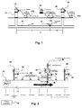
- a pipe 10 has developed a leak 12.
- a pair of hydrants 14, 16 are arranged at spaced locations.
- the leak 12 is located at a distance L 1 from hydrant 14, and distance L 2 from hydrant 16.
- the total separation of the hydrants is D.
- Hydrophone sensors 18, 20 are located at respective hydrants 14, 16. These are connected to an RF transmitter 22 which communicates with a receiver 24 connected to a computer 26. The location of the leak can be determined using LeakfinderRT software running on the computer 26.
- LeakfinderRT is a system that was developed by the National Research Council Canada for locating leaks in pressurized fluid-filled pipes, especially municipal water distribution and transmission pipes.
- LeakfinderRT utilizes the cross-correlation method to locate the hissing sound created by a pressurized fluid as it leaks out of the pipe.
- This system is fully realized in software for personal computers (PCs) running under Microsoft Windows. It uses the PC's soundcard and other multimedia components to record and play back acoustic leak signals. It also uses the PC's processor to perform the cross-correlation operation and associated digital signal conditioning operations.
- Modem PCs incorporate fast processors and high-resolution soundcards and, hence, offer several advantages over existing commercial hardware implementation of the cross-correlation method.
- Hardware components of the Leakfinder RT system include leak sensors (either vibration sensors or hydrophones), wireless signal transmission system, and a PC.
- the software can be installed on either a notebook, desktop or embedded PC that has a soundcard with a stereo line-in port and it has a friendly menu-driven interface.
- the LeakfinderRT system incorporates an enhanced correlation function.
- this function dramatically improves the definition of correlation peaks. This is important for plastic pipes, multiple-leak situations, and in settings where leak sensors have to be closely spaced.
- the enhanced correlation function is more effective than the traditional correlation function for small leaks and for situations of high background noise.
- the enhanced correlation function technique is described in US patent no. 6,453,247 , the contents of which are herein incorporated by reference.
- the cross-correlation function can be directly applied to problems involving the measurement of distance (i.e., ranging problems) or the measurement of velocity - the distance can be determined given the velocity or vice versa. Similarity between sensed leak signals is essential for obtaining an accurate time delay - hence, the assumption of a non-dispersive medium, i.e., one in which the propagation velocity does not vary with frequency. If this is not the case or if the propagating phenomenon is not sufficiently broad-band, the cross-correlation function will not have a distinct peak.
- Locating leaks in pressurized fluid-filled pipes is a classical application of the cross-correlation method. Two things make this possible. First, the propagation velocity of leak sounds in pressurized pipes is nearly constant over the dominant frequency range of leak sounds. Second, fluid-filled pipes transmit leak signals for long distances. Therefore, the shape of leak signals does not change significantly as they travel away from the leak, which is a prerequisite for a successful correlation.
- Leak noise signals are measured at the two points that bracket the location of a suspected leak.
- the cross-correlation function of the two leak signals is then calculated to determine the time delay between the two signals.
- Time delay between the two leak signals is the result of one measurement point being closer to the leak location than the other. If the two measurement points are symmetrically positioned about the leak location, leak signals will arrive simultaneously at the two points and the time delay will be zero. On the other hand, if the leak location is exactly at the position of one of the two measurement points (or, equivalently, it is not between the two points), the time shift will be equal to the distance between the measurements points divided by the propagation velocity of leak noise in the pipe.
- the correlation magnitude of two leak noise signals is the summation of their product as a function of time shift.
- the correlation value at time shift ⁇ is computed by first shifting one of the signals by ⁇ relative to the other signal. Then the two signals are multiplied, point-by-point, and the products are summed.
- the correlation function will display a peak at the time shift, which corresponds to the actual delay between the two leak noise signals (this is the time at which the two signals overlap).
- the time delay ⁇ max corresponding to the peak of the cross-correlation function is determined automatically.
- the propagation velocity can be specified if it was measured onsite or it can be calculated theoretically based on input for pipe material type and diameter.
- the cross-correlation function will have a peak corresponding to each leak. However, if the leaks are closely spaced, the peaks will overlap and distort the corresponding time delay.
- the peak width depends on the bandwidth of the leak noise; the wider the frequency bandwidth of leak signals, the narrower the cross-correlation peak.
- the frequency bandwidth of leaks in metal pipes is much wider than that of leaks in plastic ones. For metal pipes, it may be possible to resolve leaks that are 6 m apart; for plastic pipes it may not be possible to resolve accurately leaks that are less than 20 m apart.
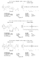
- Pumping station 28 has two 8-inch pumps that operate alternately under normal flow conditions and simultaneously under high flows, e.g., during rainstorms. Weather conditions were mostly dry and clear during the tests; it rained heavily for one hour only. Pressure in the force main at approximately 250 metres from the pumping station was about 10 psi when only one pump was on and 15 psi when both pumps kicked in.
- the pump includes a controller 40 that periodically runs and shuts down the pump, depending on a preset level of wastewater in holding tanks.
- Accelerometers, geophones and hydrophones made by Echologics Engineering Inc. were used to measure leak noise signals.
- Accelerometers were of the piezoelectric type with internal preamplifiers and had a sensitivity of 1 volt/g (where g is the unit of gravitational acceleration equal to 9.8 m/s 2 ).
- Geophones were of the rotating coil type with a special active electromagnetic interference shield and had a sensitivity of 1 volt/cm/second.
- Hydrophones were of the piezoelectric type with externally housed preamplifiers and had a sensitivity of 42 volts/bar (where bar is the unit of atmospheric pressure equal to 14.5 psi).
- Accelerometers and geophones were mounted on top of the force main by magnetically attaching them to small steel plates glued to the main's surface. Hydrophones were housed in special adaptors that were fitted into 2-inch taps in the force main. Hydrophone adaptors were equipped with 1/8-inch valves to release entrapped air after attaching them to the main. For some measurements, signals from hydrophones were attenuated by electrically connecting appropriate capacitors across input terminals of its preamplifier, in parallel with the hydrophone transducer.
- Leak signals picked up by sensors were fed into two 460 MHz RF wireless transmitters.
- a corresponding 2-channel receiver at a remote recording station picked up broadcasted signals.
- Transmitters contain a power supply source for sensor preamplifiers and specially designed automatic gain amplifier for conditioning of signals before broadcasting.
- the wireless transmission system operated in a licensed UHF frequency band and was made by Echologics Engineering Inc. Its line-of-sight range extends up to 3 km.
- Wireless transmitters were colour coded Blue and White and are referred to in this report as "Blue station” and "White station". The Blue station was always connected to the sensor closest to the pumping station.
- Wirelessly received leak noise signals were then fed into the stereo audio line-in port of a portable PC for recording and analysis by LeakfinderRT software version 5.49.
- the portable computer was of the tablet type with a 1 GHz Intel Pentium M processor (Compaq model TC1100).
- a simulated leak with adjustable flow rate was created in the selected 300-metre long test pipe section at approximately 250 metres away from the pumping station.
- the pipe was excavated and then tapped using a saddle tapping clamp with a 2-inch ball valve 30.
- a 2-inch magnetic flow meter 32 was attached after the ball valve to measure leak flow rate.
- a pressure gauge 34 was installed on the upstream side of the flow meter.
- a 2-inch gate valve was attached after the flow meter to adjust leak flow rate. Wastewater from the simulated leak was disposed through a rubber hose that ran from the outlet of the gate valve to a nearby combined sewer manhole.
- the pipe was also excavated at six other locations at about 50-metre intervals from the location of the simulated leak to attach vibration sensors 40 to the pipe's external surface to measure its acceleration or velocity.
- the pipe was tapped using saddle tapping clamps with 2-inch ball valves to attach hydrophones to measure sound waves in the wastewater inside the pipe.
- Pressure sensors 34, 38 were added to sense the pressure at the location of the hydrophones.
- Pressure sensor 36 senses pressure at the flow meter 32.
- the gate valve of the simulated leak was initially left open continuously regardless of whether the pipe was pressurized or not but later check valves were connected. Sensors were attached to the pipe at two selected locations bracketing the simulated leak. Simultaneous recording of leak signals picked up by the two sensors started once wastewater flowed from the simulated leak. Recording was terminated when leak flow stopped. Leak signals were cross-correlated onsite in real time.
- Leak flow rate was approximately 1, 3 or 5 litres per second achieved by opening the leak's 2-inch gate valve 2, 5.5 and 11 turns (valve was fully open at 11 turns).
- a leak flow rate smaller than ⁇ 1 liters per second could not be achieved, as the opening of the gate valve would quickly get blocked with dirt.
- a flow rate of 5 litres per second was the maximum achievable rate.
- Leak signals were picked up by pairs of accelerometers, geophones or hydrophones spaced at 100, 150, 200, 250, or 300 metres.
- acoustic leak signals measured with geophone pairs located at 0 and 300 m, 150 and 300 m, and 150 and 250 m also had poor cross-correlation functions and subsequently the simulated leak could not be detected.
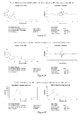
- Leak signals measured using either hydrophones or geophones had low coherence function across the whole frequency range. This indicates that the measured acoustic signal pairs were incoherent, i.e., they were unrelated or not caused by the same source (see Fig. 3 ).
- the air cavity was confirmed based on the cross-correlation function of leak signals measured with geophones at 150 and 250 m while pumping was off and air being drawn into the pipe through the leak opening.
- the cross-correlation function thus obtained had a definite center peak that corresponded to the actual position of the leak (see Fig. 4 ).
- Cross-correlation function of similar measurements of leak noise signals but with geophones at 250 and 300 m had a clear peak corresponding to out-of-bracket noise from air being drawn in through the leak (see Fig. 5 ).
- Acoustic velocity based on this peak was very close to the velocity of sound in air (equal to 340 m/s at a temperature of 15 °C sea level).
- a similar result was obtained based on leak signals measured with accelerometers. These results were taken as an indication that the sound of air being drawn into the pipe through the leak propagated through a continuous air cavity along the pipe between vibration sensors.
- a 2-inch air intake check valve was subsequently installed in the pipe at the 0 m excavation.
- the valve remained closed during pumping and promptly opened as negative pressure developed in the pipe when pumping stopped.
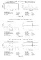
- Measurements of leak signals were then repeated with geophone pairs at 100 and 300 m and at 150 and 300 m while pumping was off and air being drawn into the pipe through both the leak opening and the air intake valve at 0 m (see Figs. 10 and 11 ).
- cross-correlation functions had a clear peak corresponding to the location of the simulated leak and another peak corresponding to the out-of-bracket noise created by air drawn into the pipe at the intake valve at 0 m.
- acoustic signals had a cross-correlation function with a pronounced out-of-bracket peak on the side of the pumping station (see Fig. 13 ). This peak was achieved after both pumps were operating continuously at the pump station for almost one hour. Both pumps were on and the valve of the simulated leak was closed during the test. This was the first time that a peak corresponding to noise from the pumping station was detected since the beginning of field tests 4 days earlier. The reason that noise from the pumping station had become detectable was believed to be that as a result of prolonged pumping the pipe had become fully filled with wastewater from the pumping station to at least the 300 m excavation.
- a continuous wastewater core made it possible for acoustic noise from the pumps to propagate to both sensors through the wastewater core. This was confirmed by the fact that acoustic velocity corresponding to the out-of-bracket peak was very close to the theoretical value of 440 m/s for a water-filled pipe of the same type and diameter.
- the gate valve of the simulated leak was then opened 2 and 5 .5 turns, while above conditions continued, the cross-correlation function had no peak corresponding to the location of the simulated leak; only a pronounced peak corresponding to the out-of-bracket noise from the pumping station (see Fig. 14 ).
- the simulated leak was detected as a distinct peak in the cross-correlation function of acoustic signals measured with hydrophones at 0 and 300 m while pumps were off and water drawn in through the leak by negative pipe pressure (e.g. see Figs. 23 , 24, and 25 ). This was achieved for small, medium and large leak openings (gate valve 2, 5.5 and 11 turns open), both soon after the leak was opened and several hours later, i.e., after the pipe had reached a steady hydraulic state. However, as expected, there was a discrepancy in the predicted location of the simulated leak. The predicted location was closer to the Blue wireless station by 5 to 30 m than the actual location.
- Discrepancy in predicted leak location is believed to be due to variation of acoustic velocity along the pipe, specifically being higher between the Blue station and leak than between the leak and White station.
- negative pressure in the pipe after pumping stops is believed to be highest near the free end of the wastewater core and becomes less severe in the direction of the pumping station.
- more of the dissolved air/gases are released as free bubbles in the White station to leak section than in the leak to Blue station section. The more bubbles in the wastewater the slower the acoustic velocity.
- Negative internal pressure that develops in force mains following pump shutdown produced favourable conditions for acoustic correlation, i.e., high-enough acoustic signals created by water drawn into the pipe through the leak while background noise was low. Success was achieved using hydrophones ⁇ 300 m apart, a distance deliberately selected as maximum river-crossing pipe length. However, predicted leak location was off by up to 10% of sensors spacing. This was expected due to the variation of acoustic velocity along wastewater pipes.
- hydraulic models When implementing acoustic correlation for river-crossing force mains, hydraulic models should first be developed for flows in these mains. The models would be used to verify if necessary conditions are met, namely that the pipe section between intended sensor locations remains fully filled with wastewater and is under negative pressure following pump shutdown.
Landscapes
- Physics & Mathematics (AREA)
- General Physics & Mathematics (AREA)
- Examining Or Testing Airtightness (AREA)
Applications Claiming Priority (1)
| Application Number | Priority Date | Filing Date | Title |
|---|---|---|---|
| US11/766,288 US7810378B2 (en) | 2007-06-21 | 2007-06-21 | Monitoring of leakage in wastewater force mains and other pipes carrying fluid under pressure |
Publications (2)
| Publication Number | Publication Date |
|---|---|
| EP2006654A2 true EP2006654A2 (de) | 2008-12-24 |
| EP2006654A3 EP2006654A3 (de) | 2010-04-28 |
Family
ID=39768928
Family Applications (1)
| Application Number | Title | Priority Date | Filing Date |
|---|---|---|---|
| EP08158471A Withdrawn EP2006654A3 (de) | 2007-06-21 | 2008-06-18 | Überwachung von Lecks in Hauptströmen von Abwasser und anderen Rohren, die Flüssigkeiten unter Druck transportieren |
Country Status (4)
| Country | Link |
|---|---|
| US (1) | US7810378B2 (de) |
| EP (1) | EP2006654A3 (de) |
| AU (1) | AU2008202689A1 (de) |
| CA (1) | CA2634739C (de) |
Cited By (9)
| Publication number | Priority date | Publication date | Assignee | Title |
|---|---|---|---|---|
| WO2012059108A1 (en) | 2010-11-05 | 2012-05-10 | Nkt Cables Group A/S | An integrity monitoring system and a method of monitoring integrity of a stationary structure |
| WO2012153147A1 (en) * | 2011-05-11 | 2012-11-15 | Syrinix Limited | Pipeline fault detection system, sensor head and method of detecting pipeline faults |
| US8717183B2 (en) | 2009-08-19 | 2014-05-06 | Severn Trent Water Limited | Leak detector |
| GB2539067A (en) * | 2015-03-27 | 2016-12-07 | Advanced Eng Solutions Ltd | Apparatus and method for the detection and monitoring of the condition of pipeline components |
| EP3115666A1 (de) | 2015-07-08 | 2017-01-11 | Ulefos Esco AS | Intelligentes ventil und automatische überwachung des zustandes von leitungen unter verwendung der intelligenten ventile |
| US9568391B2 (en) | 2013-02-14 | 2017-02-14 | Syrinix Ltd. | Pipeline monitoring unit and method |
| WO2021180281A1 (en) * | 2020-03-10 | 2021-09-16 | Kamstrup A/S | System and method for acoustic leak detection in a utility distribution system |
| US11361597B2 (en) | 2019-02-28 | 2022-06-14 | Continental Automotive Systems, Inc. | Method and system for monitoring integrity of pedestrian protection system in a vehicle |
| US11946819B2 (en) | 2020-08-04 | 2024-04-02 | Syrinix Ltd | Transient pressure event detection system and method |
Families Citing this family (64)
| Publication number | Priority date | Publication date | Assignee | Title |
|---|---|---|---|---|
| US7836760B2 (en) * | 2007-10-23 | 2010-11-23 | Saylor David J | Method and device for the assessment of fluid collection networks |
| WO2009127260A1 (de) * | 2008-04-18 | 2009-10-22 | Airbus Deutschland Gmbh | System und verfahren zum überwachen des zustands von strukturbauteilen |
| US9828757B2 (en) * | 2010-01-27 | 2017-11-28 | Ip Sensing, Inc. | Distributed control system for a vacuum sewer system |
| CA3116787C (en) | 2010-06-16 | 2023-07-11 | Mueller International, Llc | Infrastructure monitoring devices, systems, and methods |
| CN101929604B (zh) * | 2010-07-22 | 2013-07-31 | 中国石油天然气集团公司 | 高压输气管线减压波分析预测方法 |
| US9772250B2 (en) | 2011-08-12 | 2017-09-26 | Mueller International, Llc | Leak detector and sensor |
| US20130199272A1 (en) * | 2012-02-02 | 2013-08-08 | King Fahd University Of Petroleum And Minerals | In-pipe mobile cross-correlation-based system for leak detection |
| US9574716B2 (en) | 2012-03-16 | 2017-02-21 | 1589549 Alberta Ltd. | Method of reducing leaks from a pipeline |
| GB201212701D0 (en) | 2012-07-17 | 2012-08-29 | Silixa Ltd | Structure monitoring |
| JP6248936B2 (ja) * | 2012-09-28 | 2017-12-20 | 日本電気株式会社 | センサ装置、振動検知システム、センサユニット、情報処理装置、振動検知方法、及びプログラム |
| US9804053B2 (en) * | 2012-09-28 | 2017-10-31 | Nec Corporation | Defect analysis device, defect analysis method, and program |
| US9678091B2 (en) * | 2012-10-02 | 2017-06-13 | Stamford Scientific International, Inc. | In situ monitoring for wastewater treatment systems and the like |
| SG11201503041SA (en) | 2012-10-26 | 2015-05-28 | Mueller Int Llc | Detecting leaks in a fluid distribution system |
| US9983092B2 (en) * | 2013-11-12 | 2018-05-29 | Infosense, Inc. | Method and apparatus for detecting, identifying and locating anomalous events within a pressurized pipe network |
| CA2872289A1 (en) * | 2013-11-25 | 2015-05-25 | King Abdullah University Of Science And Technology | High repetition rate thermometry system and method |
| US10161240B1 (en) * | 2014-05-08 | 2018-12-25 | Vista Prevision Solutions, Inc. | Method and apparatus for testing the blowout preventer (BOP) on a drilling rig |
| CN104016136A (zh) * | 2014-06-24 | 2014-09-03 | 清华大学 | 一种近等径球料管路气力输送卡球故障监测方法 |
| CN104132248B (zh) * | 2014-07-31 | 2016-10-19 | 重庆大学 | 流体管道泄漏检测定位方法 |
| US9528903B2 (en) | 2014-10-01 | 2016-12-27 | Mueller International, Llc | Piezoelectric vibration sensor for fluid leak detection |
| WO2016077509A1 (en) * | 2014-11-13 | 2016-05-19 | Daniel Sterling | Interactive water monitoring system |
| US9835592B2 (en) | 2015-06-16 | 2017-12-05 | Mueller International, Llc | Determination of tuberculation in a fluid distribution system |
| WO2017053396A1 (en) | 2015-09-21 | 2017-03-30 | AMI Investments, LLC | Remote monitoring of water distribution system |
| US11988656B2 (en) * | 2015-09-21 | 2024-05-21 | Mcwane, Inc. | Remote monitoring of water distribution system |
| WO2017078004A1 (ja) * | 2015-11-04 | 2017-05-11 | 日本電気株式会社 | 配管状態検知装置、配管状態検知方法、コンピュータ読み取り可能記録媒体および配管状態検知システム |
| US10067092B2 (en) | 2015-12-18 | 2018-09-04 | Mueller International, Llc | Noisemaker for pipe systems |
| US10305178B2 (en) | 2016-02-12 | 2019-05-28 | Mueller International, Llc | Nozzle cap multi-band antenna assembly |
| US10283857B2 (en) | 2016-02-12 | 2019-05-07 | Mueller International, Llc | Nozzle cap multi-band antenna assembly |
| JP6297081B2 (ja) * | 2016-02-17 | 2018-03-20 | エヌ・ティ・ティ・アドバンステクノロジ株式会社 | 漏洩判定装置、漏洩判定方法及び漏洩判定プログラム |
| US10267774B2 (en) | 2016-02-29 | 2019-04-23 | Mueller International, Llc | External noisemaker for pipe systems |
| WO2017177150A1 (en) * | 2016-04-07 | 2017-10-12 | Iconac, Inc | Method and system for testing fluid filled pipes, tubes and other such vessels using sound and vibration |
| RU2620023C1 (ru) * | 2016-08-09 | 2017-05-22 | Общество с ограниченной ответственностью "ТЕХНОАС-СК" | Способ определения места течи в трубопроводе и устройство для его осуществления |
| US10565752B2 (en) | 2017-04-21 | 2020-02-18 | Mueller International, Llc | Graphical mapping of pipe node location selection |
| US10209225B2 (en) * | 2017-04-21 | 2019-02-19 | Mueller International, Llc | Sound propagation comparison with automated frequency selection for pipe condition assessment |
| US10690630B2 (en) | 2017-04-21 | 2020-06-23 | Mueller International, Llc | Generation and utilization of pipe-specific sound attenuation |
| US10539480B2 (en) | 2017-10-27 | 2020-01-21 | Mueller International, Llc | Frequency sub-band leak detection |
| US10584473B2 (en) | 2017-12-08 | 2020-03-10 | Legend Energy Advisors | Controlling a vacuum sewer system |
| EP3809107A4 (de) * | 2018-06-15 | 2021-08-04 | NEC Corporation | Leckinspektionsvorrichtung, leckinspektionsverfahren und aufzeichnungsmedium |
| US10859462B2 (en) | 2018-09-04 | 2020-12-08 | Mueller International, Llc | Hydrant cap leak detector with oriented sensor |
| US11342656B2 (en) | 2018-12-28 | 2022-05-24 | Mueller International, Llc | Nozzle cap encapsulated antenna system |
| US11525811B2 (en) | 2018-12-28 | 2022-12-13 | Industrial Technology Research Institute | Detection system and detection method |
| US11473993B2 (en) | 2019-05-31 | 2022-10-18 | Mueller International, Llc | Hydrant nozzle cap |
| US10768146B1 (en) | 2019-10-21 | 2020-09-08 | Mueller International, Llc | Predicting severity of buildup within pipes using evaluation of residual attenuation |
| US11542690B2 (en) | 2020-05-14 | 2023-01-03 | Mueller International, Llc | Hydrant nozzle cap adapter |
| US12054924B2 (en) | 2020-05-28 | 2024-08-06 | Zurn Water, Llc | Smart and connected backflow preventer assembly |
| US11726064B2 (en) | 2020-07-22 | 2023-08-15 | Mueller International Llc | Acoustic pipe condition assessment using coherent averaging |
| CN111853552B (zh) * | 2020-07-29 | 2021-03-12 | 北京市劳动保护科学研究所 | 一种供热管道泄漏在线检测定位方法 |
| TWI755010B (zh) * | 2020-07-31 | 2022-02-11 | 奕華五金股份有限公司 | 水管噪音測試方法及其設備 |
| CN112483908A (zh) * | 2020-11-23 | 2021-03-12 | 中国华能集团清洁能源技术研究院有限公司 | 一种基于声波的管道监测系统及监测方法 |
| US11609348B2 (en) | 2020-12-29 | 2023-03-21 | Mueller International, Llc | High-resolution acoustic pipe condition assessment using in-bracket pipe excitation |
| CN113217823A (zh) * | 2021-03-10 | 2021-08-06 | 北京航空工程技术研究中心 | 一种用于航煤管道泄漏监测和定位的系统及方法 |
| EP4083592B1 (de) * | 2021-04-30 | 2025-02-26 | Kamstrup A/S | System und verfahren zur akustischen leckdetektion unter verwendung eines ultraschalldurchflussmessers |
| US12196714B2 (en) | 2021-07-19 | 2025-01-14 | Mueller International, Llc | Acoustic pipeline condition assessment at resolution down to pipe stick |
| CN113916463B (zh) * | 2021-09-01 | 2023-09-19 | 西安邮电大学 | 一种危化品运输存储罐泄漏检测方法 |
| CN114264419B (zh) * | 2021-12-31 | 2025-03-14 | 重庆赛格尔汽车配件有限公司 | 一种排水管漏水检测系统 |
| CN114636527A (zh) * | 2022-03-06 | 2022-06-17 | 华东交通大学 | 一种气液混输埋地管道振动噪声特性实验测试系统及方法 |
| CN114811453A (zh) * | 2022-04-20 | 2022-07-29 | 安徽理工大学 | 一种基于延迟求和的管道泄漏声波定位方法 |
| US12564748B2 (en) | 2022-08-05 | 2026-03-03 | Clow Valve Co. division of McWane, Inc. | Remote monitoring of water distribution system |
| US12578245B2 (en) | 2022-10-28 | 2026-03-17 | Mueller International, Llc | Self-leveling sensor assembly |
| EP4658996A1 (de) * | 2023-02-03 | 2025-12-10 | The University of Adelaide | Multisensorverfahren und system zur charakterisierung einer rohrleitung |
| CN116357901A (zh) * | 2023-02-09 | 2023-06-30 | 河南省水利第一工程局集团有限公司 | 一种水利工程管道防漏检测系统及其方法 |
| US20240310233A1 (en) * | 2023-03-14 | 2024-09-19 | Ecoplant Technological Innovation Ltd | Machine learning based detection of compressed air leaks |
| US20250198875A1 (en) * | 2023-12-14 | 2025-06-19 | Mueller International, Llc | Sensor with valve release system and method |
| CN119778669B (zh) * | 2025-03-10 | 2025-09-05 | 济南市特种设备检验研究院(济南市电梯安全运行监控中心) | 一种管道泄漏检测方法 |
| CN121346192B (zh) * | 2025-12-16 | 2026-03-06 | 中铁建工集团第四建设有限公司 | 一种基于物联网的区域给水管网漏损分析预警系统 |
Citations (1)
| Publication number | Priority date | Publication date | Assignee | Title |
|---|---|---|---|---|
| US6453247B1 (en) | 2000-01-14 | 2002-09-17 | National Research Council Of Canada | PC multimedia-based leak detection system for water transmission and distribution pipes |
Family Cites Families (15)
| Publication number | Priority date | Publication date | Assignee | Title |
|---|---|---|---|---|
| US3673856A (en) | 1970-01-20 | 1972-07-04 | Pier L Panigati | Fluid operated sensor |
| FR2439990A1 (fr) | 1978-10-25 | 1980-05-23 | Gaz De France | Dispositif de detection de fuites dans une canalisation conduisant un fluide |
| US4462249A (en) | 1981-03-13 | 1984-07-31 | Adams Thomas E | Tank leakage detection method |
| JPS59170739A (ja) | 1983-03-16 | 1984-09-27 | Tokiko Yuki Kk | タンクの漏洩検査方法 |
| JPS60111132A (ja) | 1983-11-18 | 1985-06-17 | Tokiko Yuki Kk | タンクの漏洩検査方法 |
| US5052215A (en) | 1990-10-18 | 1991-10-01 | Lewis Donald E | Leak detection in storage tank bottoms by pneumatic enhancement of acoustic emissions |
| GB2250820A (en) | 1990-12-12 | 1992-06-17 | Christopher David Hill | Method of and apparatus for detecting leaks in liquid storage tanks acoustically |
| MX9205731A (es) | 1991-10-07 | 1993-11-01 | Taknology Corp International | Metodo para confirmar la presencia de una fuga en un tanque de almacenamiento de liquido. |
| DE4211038A1 (de) | 1992-04-02 | 1993-10-07 | Karl Rekers Maschinenbau Fa Di | Vorrichtung zum Prüfen der Dichtheit von Rohren |
| GB2269900A (en) | 1992-08-19 | 1994-02-23 | Christopher David Hill | Acoustic leak detection method for liquid storage tanks |
| GB2367126A (en) | 1999-08-14 | 2002-03-27 | Wt Thermo Tec Ltd | A method of testing a pressurised vessel for a leak using ultrasonic sensors |
| US6561032B1 (en) | 2000-05-15 | 2003-05-13 | National Research Council Of Canada | Non-destructive measurement of pipe wall thickness |
| GB0013731D0 (en) * | 2000-06-07 | 2000-07-26 | Metrika Limited | Detecting leaks in water distribution systems |
| GB0425211D0 (en) * | 2004-11-16 | 2004-12-15 | Metrika Ltd | Means for the location of leaks in water pipelines |
| US7328618B2 (en) | 2005-06-21 | 2008-02-12 | National Research Council Of Canada | Non-destructive testing of pipes |
-
2007
- 2007-06-21 US US11/766,288 patent/US7810378B2/en active Active
-
2008
- 2008-06-10 CA CA2634739A patent/CA2634739C/en active Active
- 2008-06-18 EP EP08158471A patent/EP2006654A3/de not_active Withdrawn
- 2008-06-18 AU AU2008202689A patent/AU2008202689A1/en not_active Abandoned
Patent Citations (1)
| Publication number | Priority date | Publication date | Assignee | Title |
|---|---|---|---|---|
| US6453247B1 (en) | 2000-01-14 | 2002-09-17 | National Research Council Of Canada | PC multimedia-based leak detection system for water transmission and distribution pipes |
Cited By (14)
| Publication number | Priority date | Publication date | Assignee | Title |
|---|---|---|---|---|
| US8717183B2 (en) | 2009-08-19 | 2014-05-06 | Severn Trent Water Limited | Leak detector |
| US9612189B2 (en) | 2010-11-05 | 2017-04-04 | Nkt Cables Group A/S | Integrity monitoring system and a method of monitoring integrity of a stationary structure |
| WO2012059108A1 (en) | 2010-11-05 | 2012-05-10 | Nkt Cables Group A/S | An integrity monitoring system and a method of monitoring integrity of a stationary structure |
| WO2012153147A1 (en) * | 2011-05-11 | 2012-11-15 | Syrinix Limited | Pipeline fault detection system, sensor head and method of detecting pipeline faults |
| US10094732B2 (en) | 2011-05-11 | 2018-10-09 | Syrinix Limited | Pipeline fault detection system, sensor head and method of detecting pipeline faults |
| GB2491804B (en) * | 2011-05-11 | 2018-01-17 | Syrinix Ltd | Pipeline fault detection system and monitor unit |
| US9568391B2 (en) | 2013-02-14 | 2017-02-14 | Syrinix Ltd. | Pipeline monitoring unit and method |
| GB2539067A (en) * | 2015-03-27 | 2016-12-07 | Advanced Eng Solutions Ltd | Apparatus and method for the detection and monitoring of the condition of pipeline components |
| GB2539067B (en) * | 2015-03-27 | 2018-08-08 | Advanced Eng Solutions Ltd | Apparatus and method for the detection and monitoring of the condition of pipeline components |
| WO2017005929A2 (en) | 2015-07-08 | 2017-01-12 | Ulefos Esco As | A smart valve and method of automated monitoring of the conditions of the pipings |
| EP3115666A1 (de) | 2015-07-08 | 2017-01-11 | Ulefos Esco AS | Intelligentes ventil und automatische überwachung des zustandes von leitungen unter verwendung der intelligenten ventile |
| US11361597B2 (en) | 2019-02-28 | 2022-06-14 | Continental Automotive Systems, Inc. | Method and system for monitoring integrity of pedestrian protection system in a vehicle |
| WO2021180281A1 (en) * | 2020-03-10 | 2021-09-16 | Kamstrup A/S | System and method for acoustic leak detection in a utility distribution system |
| US11946819B2 (en) | 2020-08-04 | 2024-04-02 | Syrinix Ltd | Transient pressure event detection system and method |
Also Published As
| Publication number | Publication date |
|---|---|
| EP2006654A3 (de) | 2010-04-28 |
| CA2634739C (en) | 2015-06-02 |
| US7810378B2 (en) | 2010-10-12 |
| CA2634739A1 (en) | 2008-12-21 |
| US20080314122A1 (en) | 2008-12-25 |
| AU2008202689A1 (en) | 2009-01-22 |
Similar Documents
| Publication | Publication Date | Title |
|---|---|---|
| US7810378B2 (en) | Monitoring of leakage in wastewater force mains and other pipes carrying fluid under pressure | |
| Hunaidi et al. | Acoustical characteristics of leak signals in plastic water distribution pipes | |
| EP2935969B1 (de) | Verfahren und system zur erfassung der positionserkennung einer molchvorrichtung in einer druckbeaufschlagten rohrleitung | |
| Hunaidi et al. | Acoustic methods for locating leaks in municipal water pipe networks | |
| Fletcher et al. | SmartBall™: a new approach in pipeline leak detection | |
| JP5583994B2 (ja) | 漏洩検知装置及び漏洩検知方法 | |
| US20120285221A1 (en) | Acoustic probe for leak detection in water pipelines | |
| US20120312078A1 (en) | Pipeline reflectometry apparatuses and methods | |
| GB2419948A (en) | Noise detecting leak location device | |
| US11892113B2 (en) | Device and method for detecting leaks and healing pipelines using twin balls technology | |
| WO2008075066A2 (en) | Leak detection device in fluid filled pipelines | |
| KR101965690B1 (ko) | 상수관로 모니터링 시스템 | |
| Cole | Methods of leak detection: an overview | |
| CN104034800A (zh) | 输送管道水力探测和运载流体管道状态评估方法及系统 | |
| Kurtz | Developments in a free-swimming acoustic leak detection system for water transmission pipelines | |
| Giunta et al. | Performance of vibroacoustic technology for pipeline leak detection | |
| Bernasconi et al. | Advanced real time and long term monitoring of transportation pipelines | |
| JP2018044862A (ja) | 水道配管における漏水位置検知装置 | |
| Khalifa et al. | Quantifying acoustic and pressure sensing for in-pipe leak detection | |
| EP0042212A1 (de) | Verfahren zur Ortung einer Leckage in Rohrleitungen | |
| Khulief et al. | On the in-pipe measurements of acoustic signature of leaks in water pipelines | |
| CN118548448A (zh) | 一种泉水直饮水管道的防漏修复装置和方法 | |
| KR102691546B1 (ko) | 도로표시못을 이용한 배관 데이터 통신 시스템 | |
| US20070005250A1 (en) | System and method for locating leaks in petroleum wells | |
| Paulson et al. | Pipe wall evaluation using acoustic pulses |
Legal Events
| Date | Code | Title | Description |
|---|---|---|---|
| PUAI | Public reference made under article 153(3) epc to a published international application that has entered the european phase |
Free format text: ORIGINAL CODE: 0009012 |
|
| AK | Designated contracting states |
Kind code of ref document: A2 Designated state(s): AT BE BG CH CY CZ DE DK EE ES FI FR GB GR HR HU IE IS IT LI LT LU LV MC MT NL NO PL PT RO SE SI SK TR |
|
| AX | Request for extension of the european patent |
Extension state: AL BA MK RS |
|
| PUAL | Search report despatched |
Free format text: ORIGINAL CODE: 0009013 |
|
| AK | Designated contracting states |
Kind code of ref document: A3 Designated state(s): AT BE BG CH CY CZ DE DK EE ES FI FR GB GR HR HU IE IS IT LI LT LU LV MC MT NL NO PL PT RO SE SI SK TR |
|
| AX | Request for extension of the european patent |
Extension state: AL BA MK RS |
|
| 17P | Request for examination filed |
Effective date: 20100810 |
|
| 17Q | First examination report despatched |
Effective date: 20100910 |
|
| AKX | Designation fees paid |
Designated state(s): AT BE BG CH CY CZ DE DK EE ES FI FR GB GR HR HU IE IS IT LI LT LU LV MC MT NL NO PL PT RO SE SI SK TR |
|
| STAA | Information on the status of an ep patent application or granted ep patent |
Free format text: STATUS: THE APPLICATION IS DEEMED TO BE WITHDRAWN |
|
| 18D | Application deemed to be withdrawn |
Effective date: 20120103 |