EP2006704A2 - Vorrichtung zur Magnetresonanzbildgebung und Verfahren zur Erzeugung von Magnetresonanzbildern - Google Patents
Vorrichtung zur Magnetresonanzbildgebung und Verfahren zur Erzeugung von Magnetresonanzbildern Download PDFInfo
- Publication number
- EP2006704A2 EP2006704A2 EP08158373A EP08158373A EP2006704A2 EP 2006704 A2 EP2006704 A2 EP 2006704A2 EP 08158373 A EP08158373 A EP 08158373A EP 08158373 A EP08158373 A EP 08158373A EP 2006704 A2 EP2006704 A2 EP 2006704A2
- Authority
- EP
- European Patent Office
- Prior art keywords
- pulse
- magnetic resonance
- time
- preparation
- transmitting
- Prior art date
- Legal status (The legal status is an assumption and is not a legal conclusion. Google has not performed a legal analysis and makes no representation as to the accuracy of the status listed.)
- Granted
Links
Images


Classifications
-
- G—PHYSICS
- G01—MEASURING; TESTING
- G01R—MEASURING ELECTRIC VARIABLES; MEASURING MAGNETIC VARIABLES
- G01R33/00—Arrangements or instruments for measuring magnetic variables
- G01R33/20—Arrangements or instruments for measuring magnetic variables involving magnetic resonance
- G01R33/44—Arrangements or instruments for measuring magnetic variables involving magnetic resonance using nuclear magnetic resonance [NMR]
- G01R33/48—NMR imaging systems
- G01R33/4828—Resolving the MR signals of different chemical species, e.g. water-fat imaging
-
- G—PHYSICS
- G01—MEASURING; TESTING
- G01R—MEASURING ELECTRIC VARIABLES; MEASURING MAGNETIC VARIABLES
- G01R33/00—Arrangements or instruments for measuring magnetic variables
- G01R33/20—Arrangements or instruments for measuring magnetic variables involving magnetic resonance
- G01R33/44—Arrangements or instruments for measuring magnetic variables involving magnetic resonance using nuclear magnetic resonance [NMR]
- G01R33/48—NMR imaging systems
- G01R33/54—Signal processing systems, e.g. using pulse sequences ; Generation or control of pulse sequences; Operator console
- G01R33/56—Image enhancement or correction, e.g. subtraction or averaging techniques, e.g. improvement of signal-to-noise ratio and resolution
- G01R33/5602—Image enhancement or correction, e.g. subtraction or averaging techniques, e.g. improvement of signal-to-noise ratio and resolution by filtering or weighting based on different relaxation times within the sample, e.g. T1 weighting using an inversion pulse
-
- G—PHYSICS
- G01—MEASURING; TESTING
- G01R—MEASURING ELECTRIC VARIABLES; MEASURING MAGNETIC VARIABLES
- G01R33/00—Arrangements or instruments for measuring magnetic variables
- G01R33/20—Arrangements or instruments for measuring magnetic variables involving magnetic resonance
- G01R33/44—Arrangements or instruments for measuring magnetic variables involving magnetic resonance using nuclear magnetic resonance [NMR]
- G01R33/48—NMR imaging systems
- G01R33/54—Signal processing systems, e.g. using pulse sequences ; Generation or control of pulse sequences; Operator console
- G01R33/56—Image enhancement or correction, e.g. subtraction or averaging techniques, e.g. improvement of signal-to-noise ratio and resolution
- G01R33/5607—Image enhancement or correction, e.g. subtraction or averaging techniques, e.g. improvement of signal-to-noise ratio and resolution by reducing the NMR signal of a particular spin species, e.g. of a chemical species for fat suppression, or of a moving spin species for black-blood imaging
-
- G—PHYSICS
- G01—MEASURING; TESTING
- G01R—MEASURING ELECTRIC VARIABLES; MEASURING MAGNETIC VARIABLES
- G01R33/00—Arrangements or instruments for measuring magnetic variables
- G01R33/20—Arrangements or instruments for measuring magnetic variables involving magnetic resonance
- G01R33/44—Arrangements or instruments for measuring magnetic variables involving magnetic resonance using nuclear magnetic resonance [NMR]
- G01R33/48—NMR imaging systems
- G01R33/54—Signal processing systems, e.g. using pulse sequences ; Generation or control of pulse sequences; Operator console
- G01R33/56—Image enhancement or correction, e.g. subtraction or averaging techniques, e.g. improvement of signal-to-noise ratio and resolution
- G01R33/561—Image enhancement or correction, e.g. subtraction or averaging techniques, e.g. improvement of signal-to-noise ratio and resolution by reduction of the scanning time, i.e. fast acquiring systems, e.g. using echo-planar pulse sequences
- G01R33/5613—Generating steady state signals, e.g. low flip angle sequences [FLASH]
-
- G—PHYSICS
- G01—MEASURING; TESTING
- G01R—MEASURING ELECTRIC VARIABLES; MEASURING MAGNETIC VARIABLES
- G01R33/00—Arrangements or instruments for measuring magnetic variables
- G01R33/20—Arrangements or instruments for measuring magnetic variables involving magnetic resonance
- G01R33/44—Arrangements or instruments for measuring magnetic variables involving magnetic resonance using nuclear magnetic resonance [NMR]
- G01R33/48—NMR imaging systems
- G01R33/54—Signal processing systems, e.g. using pulse sequences ; Generation or control of pulse sequences; Operator console
- G01R33/56—Image enhancement or correction, e.g. subtraction or averaging techniques, e.g. improvement of signal-to-noise ratio and resolution
- G01R33/565—Correction of image distortions, e.g. due to magnetic field inhomogeneities
- G01R33/56563—Correction of image distortions, e.g. due to magnetic field inhomogeneities caused by a distortion of the main magnetic field B0, e.g. temporal variation of the magnitude or spatial inhomogeneity of B0
Definitions
- the present invention relates generally to a magnetic resonance imaging (MRI) apparatus and a magnetic resonance image generating method. More particularly, it relates to a magnetic resonance imaging apparatus and a magnetic resonance image generating method for scanning a subject, in a magnetostatic field space accommodating the subject by executing, after executing a preparation pulse sequence in which preparation pulses are transmitted, an imaging sequence in which magnetic resonance signals are collected from the subject.
- MRI magnetic resonance imaging
- a magnetic resonance imaging apparatus is an apparatus to image a subject by using the nuclear magnetic resonance, and is used particularly extensively for medical purposes.
- a magnetic resonance imaging apparatus by accommodating a subject in an imaging space in which a magnetostatic field is formed, the spin of protons in that subject is aligned in the direction of that magnetostatic field to generate a magnetization vector. Then, a nuclear magnetic resonance phenomenon is caused to arise by forming a high frequency magnetic field by transmitting an RF (radio frequency) pulse of the resonance frequency. This results in flipping of the direction of the spin to vary the magnetization vector of its protons. After that, magnetic resonance (MR) signals that are generated when the spin returns its protons to return to their original state of magnetization vector in the direction of the magnetostatic field.
- MR magnetic resonance
- T2 preparation pulses transmission of T2 preparation pulses in advance to generate a T2 -emphasized image as a magnetic resonance image is known (see, for instance, Patent Document 1).
- T2 preparation pulses also called “T2 preps” or “DE (driven equilibrium) pulses”
- DE (driven equilibrium) pulses are transmitted to match, for instance, an MLEV-4 method.
- RF pulses are transmitted in a sequence of 90° RF pulse, 180° RF pulse, 180° RF pulse, -180° RF pulse, -180° RF pulse and -90° RF pulse, for instance.
- T2 emphasis is accomplished by keeping a plurality of tissues differing in transversal relaxation time (T2) in a state in which the magnetization moment of tissues longer in T2 is greater than the magnetization moment of tissues shorter in T2.
- chemical saturation pulses are transmitted in advance in a preparation pulse sequence is order to generate a fat-restrained image as a magnetic resonance image (see, for instance, Patent Document 2).
- These chemical saturation pulses also known as “Chem Sats”, “spectral saturation pulses” or “CHESS (CHEmical Shift Selective) pulses", saturates the spin of a specific tissue by transmitting in advance frequency-selective RF pulses.
- CHESS CHEmical Shift Selective
- T2 preparation pulses are used to restrain magnetic resonance signals from such tissues as muscles and the liver, and at the same time chemical saturation pulses are used to restrain magnetic resonance signals from fat, thereby to emphasize magnetic resonance signals from blood streams.
- SSFP steady state free precession
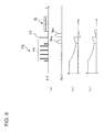
- Figs. 8 show a preparation pulse sequence PS uses both a T2 preparation pulse PR and a chemical saturation pulse CS for restraining fat as preparation pulses and an imaging pulse sequence IS to be executed after that.
- FIGs. 8 (a) is a pulse sequence graph, wherein the horizontal axis represents time and the longitudinal axis, the pulse intensity. "RF” represents the time axis of transmitting RF pulses and “GKill", the time axis of transmitting killer gradient pulses.
- FIGs. 8 are graphs showing the behaviors of the magnetization moment of fat when the pulse sequence shown in (a) is executed, wherein the horizontal axis represents time and the longitudinal axis, the magnetization moment.
- (b) shows an ideal state in which the magnetostatic field is uniform
- (c) shows an unideal state in which the magnetostatic field is not uniform.
- the T2 preparation pulse PR is transmitted as shown in Fig. 8(a) .
- a killer gradient pulse Gkp is transmitted as shown in Fig. 8(a) .
- the transverse magnetization of the spin generated by the transmission of the T2 preparation pulse PR disappears. Together with this, as shown in Fig. 8(b) , the magnetization moment of fat is recovered along with the lapse of time.
- a killer gradient pulse Gkc is transmitted.
- the imaging pulse sequence IS is executed.
- fat can be restrained by using the magnetic resonance signals collected by the execution of the imaging pulse sequence IS and a magnetic resonance image with T2 emphasis can be generated.
- the flip angle of the chemical saturation pulse CS and the length of the preparation time of waiting after the transmission of the chemical saturation pulse CS until the execution of the imaging pulse sequence IS need to be adjusted. This is to prevent magnetic resonance signals from fat from being affected by the T2 preparation pulse PR.
- the non-uniformity of the magnetostatic field may prevent the positivity or negativity of the magnetization moment of fat from being reversed when the chemical saturation pulse CS is transmitted.
- the magnetization moment of fat will take on a value different from that in the ideal state (for instance, 0) after the transmission of the chemical saturation pulse CS as shown in Fig. 8(c) .
- the magnetization moment may have a prescribed value that is not 0.
- the flip angle is set to 180° to make the chemical saturation pulse less susceptible to the non-uniformity of the magnetostatic field, the preparation time has to be extended, which would invite a T1 recovery and make the effect of transmitting the T2 preparation pulse insufficient.
- the invention provides a magnetic resonance imaging apparatus which performs, so as to collect magnetic resonance signals from a subj ect in a magnetostatic field space, scanning regarding the subject, the magnetic resonance imaging apparatus including a scanning unit which performs in the magnetostatic field space the scanning by executing, after executing a preparation pulse sequence to transmit preparation pulses, an imaging pulse sequence to collect magnetic resonance signals from the subject, wherein the scanning unit, in executing the preparation pulse sequence, excites a spin of the subject by successively transmitting a first chemical saturation pulse, a T2 preparation pulse and a second chemical saturation pulse, which is a reversed pulse; transmits a first killer gradient pulse after transmitting the first chemical saturation pulse and before transmitting the T2 preparation pulse; transmits a second killer gradient pulse after transmitting the T2 preparation pulse and before transmitting the second chemical saturation pulse; and transmits a third killer gradient pulse after transmitting the second chemical saturation pulse and before executing the imaging pulse sequence.
- the scanning unit may so transmit the first chemical saturation pulse as to make the absolute value of the flip angle 90°, and so transmit the second chemical saturation pulse as to make the absolute value of the flip angle 180°.
- the scanning unit may so transmit the first killer gradient pulse, the second killer gradient pulse and the third killer gradient pulse as to differ in magnitude from one another.
- the scanning unit may so transmit the first killer gradient pulse, the second killer gradient pulse and the third killer gradient pulse as to differ in axial direction from one another.
- the scanning unit may so transmit the first chemical saturation pulse and the second chemical saturation pulse that, in water and fat contained in the subject, the magnetic resonance signals deriving from the fat are more restrained than the magnetic resonance signals deriving from the water.
- the scanning unit may successively transmit as the T2 preparation pulses, a 90° RF pulse, a first 180° RF pulse, a second 180° RF pulse, a first -180° RF pulse, a second -180° RF pulse and a -90° RF pulse.
- the scanning unit may so transmit the T2 preparation pulses that the phases of the first 180° RF pulse, the second 180° RF pulse, the first -180° RF pulse and the second -180° RF pulse orthogonally cross the phases of the 90° RF pulse and the -90° RF pulse, respectively.
- the scanning unit may so transmit the T2 preparation pulses that, compared with a first interval of time between the center point of time of the period during which the 90° RF pulse is transmitted and the center point of time of the period during which the first 180° RF pulse is transmitted, a second interval of time between the center point of time of the period during which the 90° RF pulse is transmitted and the center point of time of the period during which the first 180° RF pulse is transmitted is made twice as long; a third interval of time between the center point of time of the period during which the second 180° RF pulse is transmitted and the center point of time of the period during which the first -180° RF pulse is transmitted is made twice as long; a fourth interval of time between the center point of time of the period during which the first -180° RF pulse is transmitted and the center point of time of the period during which the second -180° RF pulse is transmitted is made twice as long; and a fifth interval of time between the center point of time of the period during which the second -180° RF pulse
- the scanning unit may transmit each of the 90° RF pulse, the first 180° RF pulse, the second 180° RF pulse, the first -180° RF pulse, the second -180° RF pulse and the -90° RF pulse as a rectangular pulse.
- the scanning unit may repeatedly transmit to the subject RF pulses in such a repeat time that the longitudinal magnetization and transverse magnetization of the spin constitute a steady state in the subject, and so transmit a slice selecting gradient pulse for selecting the slice of the subject excited by the RF pulses, a phase encoding gradient pulse for phase-encoding magnetic resonance signals generated in the slice excited by the RF pulses, and a frequency encoding gradient pulse for frequency-encoding magnetic resonance signals generated in the slice excited by those RF pulses as to make the time integral within the repeat time zero.
- the preparation pulse sequence may be executed by so transmitting the first killer gradient pulse, the second killer gradient pulse and the third killer gradient pulse as to differ in magnitude from one another.
- the preparation pulse sequence may be executed by so transmitting the first killer gradient pulse, the second killer gradient pulse and the third killer gradient pulse as to differ in axial direction from one another.
- the invention also provides a magnetic resonance image generating method wherein, on the basis of magnetic resonance signals collected from a subject by scanning performed regarding the subject in a magnetostatic field space, a magnetic resonance image of the subject is generated, wherein the scanning is carried out by executing, after executing a preparation pulse sequence to transmit preparation pulses, an imaging pulse sequence to collect magnetic resonance signals from the subject, the preparation pulse sequence is executed by exciting a spin of the subject by successively transmitting a first chemical saturation pulse, a T2 preparation pulse and a second chemical saturation pulse, which is a reversed pulse; transmitting a first killer gradient pulse after transmitting the first chemical saturation pulse and before transmitting the T2 preparation pulse; transmitting a second killer gradient pulse after transmitting the T2 preparation pulse and before transmitting the second chemical saturation pulse; and transmitting a third killer gradient pulse after transmitting the second chemical saturation pulse and before executing the imaging pulse sequence.
- the preparation pulse sequence may be executed by so transmitting the first chemical saturation pulse as to make the absolute value of the flip angle 90°, and so transmitting the second chemical saturation pulse as to make the absolute value of the flip angle 180°.
- the preparation pulse sequence may be executed by so transmitting the first chemical saturation pulse and the second chemical saturation pulse that, in water and fat contained in the subject, the magnetic resonance signals deriving from the fat are more restrained than the magnetic resonance signals deriving from the water.
- the preparation pulse sequence may be executed by successively transmitting as the T2 preparation pulses, a 90° RF pulse, a first 180° RF pulse, a second 180° RF pulse, a first -180° RF pulse, a second -180° RF pulse and a -90° RF pulse.
- the preparation pulse sequence may be executed by so transmitting the T2 preparation pulses that the phases of the first 180° RF pulse, the second 180° RF pulse, the first -180° RF pulse and the second -180° RF pulse orthogonally cross the phases of the 90° RF pulse and the -90° RF pulse, respectively.
- the preparation pulse sequence may be executed by so transmitting the T2 preparation pulses that, compared with a first interval of time between the center point of time of the period during which the 90° RF pulse is transmitted and the center point of time of the period during which the first 180° RF pulse is transmitted, a second interval of time between the center point of time of the period during which the 90° RF pulse is transmitted and the center point of time of the period during which the first 180° RF pulse is transmitted is made twice as long; a third interval of time between the center point of time of the period during which the second 180° RF pulse is transmitted and the center point of time of the period during which the first -180° RF pulse is transmitted is made twice as long; a fourth interval of time between the center point of time of the period during which the first -180° RF pulse is transmitted and the center point of time of the period during which the second -180° RF pulse is transmitted is made twice as long; and a fifth interval of time between the center point of time of the period during which the second -
- the preparation pulse sequence may be executed by transmitting each of the 90° RF pulse, the first 180° RF pulse, the second 180° RF pulse, the first -180° RF pulse, the second -180° RF pulse and the -90° RF pulse as a rectangular pulse.
- the imaging pulse sequence may be executed by repeatedly transmitting to the subject RF pulses in such a repeat time that the longitudinal magnetization and transverse magnetization of the spin constitute a steady state in the subject, and so transmitting a slice selecting gradient pulse for selecting the slice of the subject excited by the RF pulses, a phase encoding gradient pulse for phase-encoding magnetic resonance signals generated in the slice excited by the RF pulses, and a frequency encoding gradient pulse for frequency-encoding magnetic resonance signals generated in the slice excited by those RF pulses as to make the time integral within the repeat time zero.
- a magnetic resonance imaging apparatus and a magnetic resonance image generating method that permit enhancement of the efficiency of diagnosis and improvement of the quality of images can be provided.
- Fig. 1 is a configurational diagram showing the configuration of a magnetic resonance imaging apparatus 1 in a mode for implementing various embodiments of the invention.
- the magnetic resonance imaging apparatus 1 in this mode for implementation, having a scanning unit 2 and an operation console unit 3 as shown in Fig. 1 , scans a subject SU and then generates a magnetic resonance image of the subject SU using as raw data the magnetic resonance signals obtained by the scanning.
- the scanning unit 2 here has a magnetostatic field magnet unit 12, a gradient coil unit 13, an RF coil unit 14, a subject moving unit 15, an RF driving unit 22, a gradient driving unit 23 and a data collecting unit 24 as shown in Fig. 1 .
- the operation console unit 3 has a control unit 30, an image reconstruction unit 31, an operation unit 32, a display unit 33 and a storage unit 34 as shown in Fig. 1 .
- parts corresponding to the magnetostatic field magnet unit 12 and the gradient coil unit 13 are represented by faces cut along a plane in the y direction.
- the scanning unit 2 will be described.
- the scanning unit 2 includes an imaging space B in which a magnetostatic field is formed as shown in Fig. 1 , and accommodates the subject SU in that imaging space B.
- the scanning unit 2 is formed to have a cylindrical shape, for instance, and the columnar space in its central part is used as the imaging space B to accommodate the subject SU.
- the scanning unit 2 transmits RF pulses so as to excite a spin of the subject SU in the imaging space B accommodating that subject SU, at the same time executes the imaging pulse sequence IS by transmitting gradient pulses, and collects magnetic resonance signals generated in that subject SU.
- the scanning unit 2 executes, before the execution of this imaging pulse sequence IS, the preparation pulse sequence PS of transmitting preparation pulses in the imaging space B.
- the scanning unit 2 excites a spin of the subject SU by successively transmitting a first chemical saturation pulse, a T2 preparation pulse and a second chemical saturation pulse, which is a reversedpulse.
- a first chemical saturation pulse After transmitting the first chemical saturation pulse and before transmitting the T2 preparation pulse, it transmits a first killer gradient pulse.
- a second killer gradient pulse after transmitting the T2 preparation pulse and before transmitting the second chemical saturation pulse.
- the scanning unit 2 so transmits here the first killer gradient pulse, the second killer gradient pulse and the third killer gradient pulse as to be different in at least one of the size and the axial direction.
- the scanning unit 2 executes the imaging pulse sequence IS by one of SSFP (Steady State Free Precession) type imaging methods known as, for instance, FIESTA, True FISP and Balanced TFE.
- SSFP Steady State Free Precession
- the magnetostatic field magnet unit 12 is a horizontal magnetic field unit, for instance, and its superconducting magnet (not shown) forms a magnetostatic field in the imaging space B in which the subject SU is accommodated in the direction of the body axis of the subject SU.
- the magnetostatic field magnet unit 12 may as well be a vertical, instead of horizontal, magnetic field unit, and the magnetostatic field may be formed in the direction in which a pair of permanent magnets face each other.
- the gradient coil unit 13 by transmitting gradient pulses to the imaging space B in which a magnetostatic field is formed thereby to form a gradient magnetic field, adds spatial positional information to the magnetic resonance signals received by the RF coil unit 14.
- the gradient coil unit 13 here consists of three lines to form the gradient magnetic fields to match the three mutually orthogonal axial directions including the x direction, the y direction and the z direction. They form gradient magnetic fields by transmitting gradient pulses in each of the frequency encoding direction, the phase encoding direction and the slice selecting direction in accordance with control signals from the control unit 30.
- the gradient coil unit 13 by transmitting a gradient pulse in the slice selecting direction of the subject SU, selects a slice of the subject SU that the RF coil unit 14 excites by transmitting an RF pulse. Also, the gradient coil unit 13 phase-encodes the magnetic resonance signals from the slice excited by the RF pulse by transmitting a gradient pulse in the phase encoding direction of the subject SU. And the gradient coil unit 13, by transmitting a gradient pulse in the frequency encoding direction of the subject SU, frequency-encodes the magnetic resonance signals from the slice excited by the RF pulse.
- the RF coil unit 14 as shown in Fig. 1 , is so arranged as to surround the subject SU.
- the RF coil unit 14 transmits in accordance with a control signal from the control unit 30 the RF pulse, which is an electromagnetic wave, to the imaging space B in which a magnetostatic field is formed by the magnetostatic field magnet unit 12 and thereby forms a high frequency magnetic field.
- This causes a spin of protons in the subject SU to be excited.
- the RF coil unit 14 transmits as magnetic resonance signals the electromagnetic wave generated when the excited spin of protons returns to the original magnetization vector.
- the cradle 15a moves the cradle moving unit 15b between inside and outside the imaging space B in accordance with a control signal from the control unit 30.
- the cradle 15a is a table having a mount face on which the subject SU is to be mounted and, moved by the cradle moving unit 15b in the horizontal direction xz and the vertical direction y as shown in Fig. 1 , is moved in and out of the imaging space B in which a magnetostatic field is formed.
- the cradle moving unit 15b moves the cradle 15a and causes it to be accommodated into the imaging space B from outside.
- the cradle moving unit 15b is equipped with a roller type driving mechanism, for instance, which drives rollers with an actuator to move the cradle 15a in the horizontal direction xz.
- the cradle moving unit 15b is equipped with an arm type driving mechanism, for instance, which moves the cradle 15a in the vertical direction y by varying the angle between two crossing arms.
- the RF driving unit 22 transmits the RF pulse into the imaging space B by driving the RF coil unit 14 and thereby forms a high frequency magnetic field.
- the RF driving unit 22 after modulating a signal from an RF oscillator into a signal of a prescribed timing and a prescribed envelope by using a gate modulator in accordance with a control signal from the control unit 30, amplifies with an RF power amplifier that signal modulated by the gate modulator and outputs it to the RF coil unit 14 to cause an RF pulse to be transmitted.
- the gradient driving unit 23 by driving the gradient coil unit 13 in accordance with a control signal from the control unit 30, generates a gradient magnetic field in the imaging space B in which a magnetostatic field is formed.
- the gradient driving unit 23 has three lines of driving circuits (not shown) matching the three lines of the gradient coil unit 13.
- the data collecting unit 24 in accordance with a control signal from the control unit 30, collects magnetic resonance signals received by the RF coil unit 14.
- a phase detector phase-detects the magnetic resonance signals received by the RF coil unit 14 with the output of the RF oscillator of the RF driving unit 22 as the reference signal. After that, these magnetic resonance signals that are analog signals are converted into digital signals by using an A/D converter and outputted.
- the operation console unit 3 will be described.
- the operation console unit 3 so performs control that the scanning unit 2 executes a scan with respect to the subject, generates an image of the subject on the basis of the magnetic resonance signals obtained by that scan executed by the scanning unit 2 and displays the generated image.
- the control unit 30, having a computer and a memory storing programs to cause the computer to perform prescribed data processing, controls the constituent units.
- the control unit 30 generates a control signal for controlling the scanning unit 2 on the basis of operational data. After that, it outputs the generated control signal to the scanning unit 2 to control the scanning unit 2.
- it outputs a control signal to each of the RF driving unit 22, the gradient driving unit 23 and the data collecting unit 24 to so control the operation of each unit as to match the set scanning conditions.
- the image reconstruction unit 31 having a computer and a memory storing programs to cause the computer to perform prescribed data processing, executes image reconstruction processing in accordance with control signals from the control unit 30 to reconstruct an image regarding the subject.
- execution of a scan by the scanning unit 2 regarding an imaging area thereby to execute Fourier transform processing on magnetic resonance signals so collected as to match a k space constitutes performance of image reconstruction processing to reconstruct a slice image of this subject.
- the image reconstruction unit 31 generates the slice image from the magnetic resonance signals collected by the scanning unit 2 as raw data.
- the image reconstruction unit 31 outputs to the display unit 33 the data of that reconstructed image.
- the operation unit 32 includes operating devices such as a keyboard and a pointing device, and the operator carries out the operation of various units by inputting operational data to a plurality of input items by using the operating devices.
- the operation unit 32 here is a so-called graphical user interface, which displays on the display unit 33 a screen indicating input items, and the operator watching the screen inputs operational data. And the operator carries out operation by outputting those operational data to the control unit 30. More specifically, the operation unit 32 has as these input items the scan parameters of the scan to be executed by the scanning unit 2, and the operational data are so inputted as to match the scan parameters.
- the operation unit 32 has subject information on the subject to be scanned by the scanning unit 2 as its input items, and the operational data are so inputted as to match the subject information.
- the display unit 33 composed of a display device including a monitor such as an LCD (liquid crystal display), displays on its display screen an image in accordance with control signals from the control unit 30. For instance, the display unit 33 displays side by side on its display screen a plurality of images including one showing the input items of the operational data inputted by the operator to the operation unit 32 and another showing a dialog box for inputting those operational data. More specifically, the display unit 33 displays scan parameters including the number of echoes, echo duration, repeat time and band width, a dialog box to which subject information including the name and body weight of the subject is inputted, and buttons for instructing a shift of the cradle and instructing the start of scanning, and each input item is displayed correspondingly on the display screen as character information. Also the display unit 33, receiving image data of the imaging area reconstructed by the image reconstruction unit 31, displays their image on the display screen. Thus, the display unit 33 displays a magnetic resonance image, reconstructed as a medical image, on the display screen.
- a display device including a monitor such as an
- the storage unit 34 composed of a storage device such as a memory, stores various sets of data.
- the storage unit 34 is accessed by the control unit 30 as required for the data stored therein.
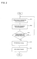
- Fig. 2 is a flow chart of the operation performed when picking up an image of the subject SU in Implementation Mode 1 for various embodiments of the invention.
- the preparation pulse sequence PS is executed (S11).
- the scanning unit 2 executes the preparation pulse sequence PS.
- Fig. 3 is a pulse sequence diagram showing the preparation pulse sequence PS in Implementation Mode 1 for the invention.
- (a) is the time axis of transmitting the RF pulses RF and (b), the time axis of transmitting the killer gradient pulses Gkill as the gradient pulses, for each of which the horizontal axis represents the time t and the vertical axis, the pulse intensity.
- Gkill represents at least one axial direction out of the slice selecting direction, the phase encoding direction and the frequency encoding direction.
- the time integral is an integral defined by the pulse intensity and the time t.
- a spin of the subject SU is excited by successively transmitting a first chemical saturation pulse CS1, the T2 preparation pulse PR and a second chemical saturation pulse CS2, which is a reversed pulse.
- a first killer gradient pulse Gk1 is transmitted after transmitting the first chemical saturation pulse CS1 and before transmitting the T2 preparation pulse PR
- a second killer gradient pulse Gk2 is transmitted after transmitting the T2 preparation pulse PR and before transmitting the second chemical saturation pulse CS2
- a third killer gradient pulse Gk3 is transmitted after transmitting the second chemical saturation pulse CS2 and before transmitting the imaging pulse sequence IS to be described afterwards.
- first the first chemical saturation pulse CS1 is transmitted.
- this first chemical saturation pulse CS1 is transmitted between a first point of time t1 and a second point of time t2. It is so transmitted as to make, for instance, the absolute value of the flip angle 90° and the length of time between the first point of time t1 and the second point of time t2 8 msec.
- the first chemical saturation pulse CS1 is so transmitted that, in water and fat contained in the subject SU, the magnetic resonance signals deriving from the fat are more restrained than the magnetic resonance signals deriving from the water. Namely, a frequency-selective RF pulse is transmitted to saturate the fat.
- the first killer gradient pulse Gk1 is transmitted as shown in Fig. 3 .
- this first killer gradient pulse Gk1 is so transmitted between the second point of time t2 and a third point of time t3 as to generate a gradient magnetic field which causes the transverse magnetization of the spin to disappear. It is so transmitted as to make, for instance, the length of time between the second point of time t2 and the third point of time t3 5 msec.
- the T2 preparation pulse PR is transmitted as shown in Fig. 3 .
- T2 preparation pulses PR are so transmitted as to match the MLEV-4 method. More specifically, as the T2 preparation pulses PR, a 90° RF pulse PR11, a first 180° RF pulse PR21, a second 180° RF pulse PR22, a first -180° RF pulse PR31, a second -180° RF pulse PR32 and a -90° RF pulse PR41 are successively transmitted each for a 50 msec duration of application (also known as TE or time of echo).
- a 50 msec duration of application also known as TE or time of echo
- the 90° RF pulse PR11, the first 180° RF pulse PR21, the second 180° RF pulse PR22, the first -180° RF pulse PR31, the second -180° RF pulse PR32 and the -90° RF pulse PR41 are transmitted as rectangular pulses.
- these T2 preparation pulses PR are so transmitted that the phases of the first 180° RF pulse PR21 and the second 180° RF pulse PR22 orthogonally cross the phase of the 90° RF pulse PR11 and the phases of the first -180° RF pulse PR31 and the second -180° RF pulse PR32 orthogonally cross the phase of the -90° RF pulse PR41.
- T2 preparation pulses PR are so transmitted as to make the ratio of time intervals between the 90° RF pulse PR11, the first 180° RF pulse PR21, the second 180° RF pulse PR22, the first -180° RF pulse PR31, the second -180° RF pulse PR32 and the -90° RF pulse PR41 1:2:2:2:1.
- the 90° RF pulse PR11 is so transmitted as to flip a spin with its phase in the x direction and at a flip angle of 90° as shown in Fig. 3 .
- this 90° RF pulse PR11 is transmitted in the period from the third point of time t3 when the transmission of the first killer gradient pulse Gk1 has been completed until a fourth point of time t4 a prescribed interval afterwards.
- the spin of the subject is turned by 90° around the x direction as the center axis.
- the first 180° RF pulse PR21 is so transmitted as to cause a spin to be flipped with its phase being in the y direction orthogonal to the x direction at a flip angle of 180°.
- this first 180° RF pulse PR21 is started at a fifth point of time t5 a prescribed interval after the fourth point of time t4 when the transmission of the 90° RF pulse PR11 has been completed, and this first 180° RF pulse PR21 is transmitted from that fifth point of time t5 until a sixth point of time t6 a prescribed interval afterwards.
- the second 180° RF pulse PR22 is so transmitted as to cause a spin to be flipped with its phase being in the y direction at a flip angle of 180°.
- this second 180° RF pulse PR22 is started at a seventh point of time t7 a prescribed interval after the sixth point of time t6 when the transmission of the first 180° RF pulse PR21 has been completed, and this second 180° RF pulse PR22 is transmitted from that seventh point of time t7 until an eighth point of time t8 a prescribed interval afterwards.
- the second 180° RF pulse PR22 is so transmitted as to make a second interval of time ⁇ 2 between the center point of time tr21 of the period during which the first 180° RF pulse PR21 is transmitted (t5 to t6) and the center point of time tr22 of the period during which the second 180° RF pulse PR22 is transmitted (t7 to t8) twice as long as a first interval of time ⁇ 1 between the center point of time tr11 of the period during which the 90° RF pulse PR11 is transmitted (t3 to t4) and the center point of time tr21 of the period during which the first 180° RF pulse PR21 is transmitted (t5 to t6).
- the first -180° RF pulse PR31 is so transmitted as to cause a spin to be flipped with its phase being in the y direction at a flip angle of -180°.
- this first -180° RF pulse PR31 is started at a ninth point of time t9 a prescribed interval after the eighth point of time t8 when the transmission of the second 180° RF pulse PR22 has been completed, and this first -180° RF pulse PR31 is transmitted from the ninth point of time t9 until a 10th point of time t10 a prescribed interval afterwards.
- the first -180° RF pulse PR31 is so transmitted as to make a third interval of time ⁇ 3 between the center point of time tr22 of the period during which the second 180° RF pulse PR22 is transmitted (t7 to t8) and the center point of time tr31 of the period during which the first -180° RF pulse PR31 is transmitted (t9 to t10) twice as long as the first interval of time ⁇ 1 between the center point of time tr11 of the period during which the 90° RF pulse PR11 is transmitted (t3 to t4) and the center point of time tr21 of the period during which the first 180° RF pulse PR21 is transmitted (t5 to t6).
- the second -180° RF pulse PR32 is so transmitted as to cause a spin to be flipped with its phase being in the y direction at a flip angle of -180°.
- this second -180° RF pulse PR32 is started at an 11th point of time t11 a prescribed interval after the 10th point of time t10 when the transmission of the first -180° RF pulse PR31 has been completed, and this second 180° RF pulse PR22 is transmitted from that 11th point of time t11 until a 12th point of time t12 a prescribed interval afterwards.
- the second -180° RF pulse PR32 is so transmitted as to make a fourth interval of time ⁇ 4 between the center point of time tr31 of the period during which the first -180° RF pulse PR31 is transmitted (t9 to t10) and the center point of time tr32 of the period during which the second -180° RF pulse PR32 is transmitted (t11-t12) twice as long as the first interval of time ⁇ 1 between the center point of time tr11 of the period during which the 90° RF pulse PR11 is transmitted (t3 to t4) and the center point of time tr21 of the period during which the first 180° RF pulse PR21 is transmitted (t5 to t6).
- the -90° RF pulse PR41 is so transmitted as to cause a spin to be flipped with its phase being in the x direction at a flip angle of -90°.
- this -90° RF pulse PR41 is started at a 13th point of time t13 a prescribed interval after the 12th point of time t12 when the transmission of the second -180° RF pulse PR32 has been completed, and this -90° RF pulse PR41 is transmitted from that 13th point of time t13 until a 14th point of time t14 a prescribed interval afterwards.
- the -90° RF pulse PR41 is so transmitted as to make a fifth interval of time ⁇ 5 between the center point of time tr32 of the period during which the second -180° RF pulse PR32 is transmitted (t11 to t12) and the center point of time tr41 of the period during which the -90° RF pulse PR41 is transmitted (t13-t14) twice as long as the first interval of time ⁇ 1 between the center point of time tr11 of the period during which the 90° RF pulse PR11 is transmitted (t3 to t4) and the center point of time tr21 of the period during which the first 180° RF pulse PR21 is transmitted (t5 to t6).
- the magnetization moment of tissues longer in T2 can be greater than the magnetization moment of tissues shorter in T2.
- the second killer gradient pulse Gk2 is transmitted.
- this second killer gradient pulse Gk2 is so transmitted between the 14th point of time t14 when the transmission of the T2 preparation pulses PR has been completed and a 15th point of time t15 a prescribed interval afterwards as to generate a gradient magnetic field which causes the transverse magnetization of the spin to disappear. It is so transmitted as to make, for instance, the length of time between the 14th point of time t14 and the 15th point of time t15 5 msec. In this mode for implementation, transmission is so accomplished as to differentiate the magnitude of the second killer gradient pulse Gk2 from that of the first killer gradient pulse Gk1 though in the same axial direction as the first killer gradient pulse Gk1.
- the second killer gradient pulse Gk2 may be transmitted in a different axial direction from the first killer gradient pulse Gk1.
- the second chemical saturation pulse CS2 is transmitted.
- this second chemical saturation pulse CS2 is transmitted as a reversed pulse in the period from the 15th point of time t15 when the transmission of the second killer gradient pulse Gk2 has been completed until a 16th point of time t16 a prescribed interval afterwards. More specifically, the transmission is so accomplished as to make the interval between the 15th point of time t15 and the 16th point of time t16 8 msec with the absolute value of the flip angle being 180°, and the positivity or negativity of the magnetization moment is reversed. Further in this mode for implementation, the second chemical saturation pulse CS2 is so transmitted that, in water and fat contained in the subject SU, the magnetic resonance signals deriving from the fat are more restrained than the magnetic resonance signals deriving from the water. Namely, a frequency-selective RF pulse is transmitted to saturate the fat.
- the third killer gradient pulse Gk3 is transmitted.
- this third killer gradient pulse Gk3 is so transmitted between the 16th point of time t16 when the transmission of the second chemical saturation pulse CS2 has been completed and a 17th point of time t17 a prescribed interval afterwards as to generate a gradient magnetic field which causes the transverse magnetization of the spin to disappear.
- transmission is so accomplished as to make the pulse width of the second killer gradient pulse Gk2 the same as that of the third killer gradient pulse Gk3. It is so transmitted as to make, for instance, the length of time between the 16th point of time t16 and the 17th point of time t17 5 msec.
- transmission is so accomplished as to differentiate the first killer gradient pulse Gk1, the second killer gradient pulse Gk2 and the third killer gradient pulse Gk3 from one another in magnitude.
- transmission is so accomplished as to make the time integral of transmitting the third killer gradient pulse Gk3 differ from the time integral of transmitting the first killer gradient pulse Gk1 and the second killer gradient pulse Gk2.
- the third killer gradient pulse Gk3 is to be so transmitted to have the same pulse width as those of the first killer gradient pulse Gk1 and the second killer gradient pulse Gk2
- transmission is so accomplished as to make the pulse intensity of the third killer gradient pulse Gk3 differ from those of the first killer gradient pulse Gk1 and the second killer gradient pulse Gk2.
- the imaging pulse sequence IS is executed as charted in Fig. 2 (S21).
- the preparation pulse sequence PS is executed and, after waiting for a prescribed length of preparation time, the scanning unit 2 executes the imaging pulse sequence IS.
- the imaging pulse sequence IS is executed by an SSFP type imaging method to collect magnetic resonance signals from the subject.
- Fig. 4 is a pulse sequence diagram showing the imaging pulse sequence IS to be executed in a mode for implementing various embodidments of the invention.
- RF represents the time axis on which RF pulses are transmitted;
- Gslice the time axis on which gradient pulses are transmitted in the slice selecting-encoding direction;
- Gread the time axis on which gradient pulses are transmitted in the read-out direction;
- Gwarp the time axis on which gradient pulses are transmitted in the phase encoding direction; in every case, the horizontal axis represents the time t and the vertical axis, the pulse intensity.
- RF pulses RF are repeatedly transmitted to the subject SU.
- the scanning unit 2 transmits the RF pulses RF in such a repeat time TR that the longitudinal magnetization and transverse magnetization of the spin constitute a steady state in the subject SU.
- a slice selecting gradient pulse Gs for selecting the slice of the subject SU excited by that RF pulse RF as an imaging area, a phase encoding gradient pulse Gp for phase-encoding magnetic resonance signals generated in the slice excited by that RF pulse, and a frequency encoding gradient pulse Gr for frequency-encoding magnetic resonance signals generated in the slice excited by that RF pulse are transmitted within the repeat time TR.
- the slice selecting gradient pulse, the phase encoding gradient pulse and the frequency encoding gradient pulse are so transmitted to the subject SU as to make the time integral within the repeat time TR zero.
- transverse magnetization is rewound within the repeat time TR and the phase encoded by the gradient magnetic field is reset.
- control unit 30 judges whether or not all the imaging data corresponding to the k space have been collected.
- the execution of the preparation pulse sequence PS (S11) and the execution of the imaging pulse sequence IS (S21) are repeated in succession as shown in Fig. 2 .
- imaging data are collected until the k space is wholly filled.
- the image reconstruction unit 31 reconstructs an image regarding the subject SU.
- the display unit 33 receives all the data regarding the image of the subject SU from the image reconstruction unit 31, and displays that image on the display screen.
- a spin of the subject SU is excited by successively transmitting the first chemical saturation pulse CS1, the T2 preparation pulse PR and the second chemical saturation pulse CS2, which is a reversed pulse.
- the first killer gradient pulse Gk1 is transmitted; after transmitting the T2 preparation pulse PR and before transmitting the second chemical saturation pulse CS2, the second killer gradient pulse Gk2 is transmitted; and after transmitting the second chemical saturation pulse CS2 and before transmitting the imaging pulse sequence IS, the third killer gradient pulse Gk3 is transmitted.
- the first chemical saturation pulse CS1 and the second chemical saturation pulse CS2 are so transmitted that, in water and fat contained in the subject SU, the magnetic resonance signals deriving from the fat are selectively more restrained than the magnetic resonance signals deriving from the water. Also, the first chemical saturation pulse CS1 is so transmitted as to make the absolute value of the flip angle 90°, and the second chemical saturation pulse CS2 is so transmitted as to make the absolute value of the flip angle 180°. Further, the second killer gradient pulse Gk2 and the third killer gradient pulse Gk3 are so transmitted as to make their pulse width the same and thereby to cause them to function as crasher gradient pulses. By doing so, magnetic resonance images having undergone not only fat restraint but also T2 emphasis can be generated without being affected by the non-uniformity of magnetostatic fields.
- Figs. 5 are graphs showing the behaviors of the magnetization moment of fat when the preparation pulse sequence PS is executed in the mode for implementing various embodiments of the invention.
- FIGs. 5 (a) is a pulse sequence chart, wherein the horizontal axis represents the time and the vertical axis, the pulse intensity. And “RF” represents the time axis of transmitting RF pulses and “GKill", the time axis of transmitting killer gradient pulses.
- This (a) schematically illustrates the pulse sequence shown in Fig. 3 and Fig. 4 cited above.
- FIGs. 5 are graphs showing the behaviors of the magnetization moment of fat when the pulse sequence shown in (a) was executed, wherein the horizontal axis represents the time and the vertical axis, the magnetization moment.
- (b) shows an ideal state in which the magnetostatic field is uniform
- (c) shows an unideal state in which the magnetostatic field is not uniform.
- the magnetostatic field is in the ideal state in which the magnetostatic field is uniform, the magnetization moment of fat will become 0 as shown in Fig. 5(b) .
- the magnetization moment of fat will have a prescribed value as it is not flipped at a flip angle of 90° but is flipped at a flip angle of, for instance, 60° as shown in Fig. 5(c) .
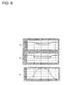
- Figs. 6 are graphs showing the bandwidths of fat restraint in the mode for implementing various embodiments of the invention.
- FIGs. 6 shows the result of simulation of a conventional case and (b), the result of simulation in this mode for implementation. More specifically, in the conventional case a preparation pulse sequence which is similar to the preparation pulse sequence PS in this mode for implementation except that the first chemical saturation pulse CS1 is not transmitted and the flip angle of the second chemical saturation pulse CS2 is 90° is executed. Further, the simulation was carried out here under the conditions that the chemical saturation pulse was in a Fermi function shape as shown in (c), the offset frequency was -220 Hz, the Fermi radius was 110 Hz, the Fermi width was 20 Hz and the flip angle was 90°.
- the half width in this mode for implementation shown in (b) is greater than the half width in the conventional case shown in (a). It is seen that, for this reason, this mode for implementation is hardly affected by the non-uniformity of the magnetostatic field.
- Figs. 7 are drawings showing reconstructed images in the mode for implementing various embodiments of the invention.
- (a) shows the conventional case and (b), the case in this mode for implementation.
- Fig. 7(a) in the conventional case, there are involved parts where magnetic resonance signals from fat on the body surface are not restrained (arrowed parts) at the ends where the magnetostatic field is not uniform, resulting in the occurrence of artifacts. Unlike that, in this mode for implementation, magnetic resonance signals from fat on the body surface are restrained (solid arrowed parts) at the ends where the magnetostatic field is not uniform as shown in Fig. 7(b) , and fat signals in bones are also restrained (broken arrowed parts), resulting in the prevention of artifact occurrence.
- the magnetization moments take on similar values in both cases including the ideal state in which the magnetostatic field is uniform and the unideal state in which the magnetostatic field is not uniform.
- the flip angles of the first chemical saturation pulse CS1 and the second chemical saturation pulse CS2 and the length of preparation time until the imaging pulse sequence IS is executed after the execution of the preparation pulse sequence PS with the assumption that the magnetostatic field is in the ideal state magnetic resonance signals from fat can be effectively restrained without having to exactly adjusting the flip angles and the length of preparation time.
- fat signals can be restrained without relying on the magnitude of the longitudinal magnetization of before the application of the series of RF pulses.
- this feature is useful for image diagnosis because fat signals can be effectively restrained.
- the magnetic resonance imaging apparatus 1 in the mode for implementation described above corresponds to the magnetic resonance imaging apparatus according to various embodiments of the invention.
- the scanning unit 2 in the above-described mode for implementation corresponds to the scanning unit according to various embodiments of the invention.
- the image reconstruction unit 31 in the above-described mode for implementation corresponds to the image reconstruction unit according to various embodiments of the invention.
- the display unit 33 corresponds to the display unit according to various embodiments of the invention.
- the flip angle is not limited to any of the aforementioned values. More specifically, as the T2 preparation pulses PR, the 90° RF pulse PR11, the first 180° RF pulse PR21, the second 180° RF pulse PR22, the first -180° RF pulse PR31, the second -180° RF pulse PR32 and the -90° RF pulse PR41 are successively transmitted, but the choice is not limited to these.
- the time integral, phase and transmission timing of each pulse can be set as desired.
- the spin echo and the stimulated echo can be prevented from occurring unexpectedly by so accomplishing transmission as to differentiate the time integral of transmitting each of the first killer gradient pulse Gk1, the second killer gradient pulse Gk2 and the third killer gradient pulse Gk3 in this mode for implementation, the way of prevention is not limited to this.
- the first killer gradient pulse Gk1, the second killer gradient pulse Gk2 and the third killer gradient pulse Gk3 may as well be transmitted on mutually different mutually different axes on the x axis, the y axis and the z axis.
- the imaging sequence may be accomplished in any of various other techniques than the SSFP method including FSE (Fast Spin Echo), SE (Spin Echo) , GRE (Gradient Recalled Echo) and SPGR (Spoiled GRASS).
- FSE Fest Spin Echo
- SE Spin Echo
- GRE Gradient Recalled Echo
- SPGR Spoiled GRASS
Landscapes
- Physics & Mathematics (AREA)
- High Energy & Nuclear Physics (AREA)
- Condensed Matter Physics & Semiconductors (AREA)
- General Physics & Mathematics (AREA)
- Magnetic Resonance Imaging Apparatus (AREA)
Applications Claiming Priority (1)
| Application Number | Priority Date | Filing Date | Title |
|---|---|---|---|
| JP2007162649A JP5037236B2 (ja) | 2007-06-20 | 2007-06-20 | 磁気共鳴イメージング装置および磁気共鳴画像生成方法 |
Publications (3)
| Publication Number | Publication Date |
|---|---|
| EP2006704A2 true EP2006704A2 (de) | 2008-12-24 |
| EP2006704A3 EP2006704A3 (de) | 2009-12-30 |
| EP2006704B1 EP2006704B1 (de) | 2011-08-24 |
Family
ID=39811424
Family Applications (1)
| Application Number | Title | Priority Date | Filing Date |
|---|---|---|---|
| EP08158373A Ceased EP2006704B1 (de) | 2007-06-20 | 2008-06-17 | Vorrichtung zur Magnetresonanzbildgebung und Verfahren zur Erzeugung von Magnetresonanzbildern |
Country Status (4)
| Country | Link |
|---|---|
| US (1) | US7759934B2 (de) |
| EP (1) | EP2006704B1 (de) |
| JP (1) | JP5037236B2 (de) |
| CN (1) | CN101327123B (de) |
Families Citing this family (15)
| Publication number | Priority date | Publication date | Assignee | Title |
|---|---|---|---|---|
| JP5799087B2 (ja) | 2010-05-27 | 2015-10-21 | コーニンクレッカ フィリップス エヌ ヴェ | 機器検出を伴う磁気共鳴検査 |
| US9030201B2 (en) | 2011-01-27 | 2015-05-12 | Siemens Medical Solutions Usa, Inc. | System and method for independent manipulation of a fat and a water component in magnetic resonance imaging |
| US8797031B2 (en) | 2011-01-27 | 2014-08-05 | Siemens Medical Solutions Usa, Inc. | MR imaging system for discriminating between imaged tissue types |
| CN108318843B (zh) * | 2011-09-22 | 2021-11-16 | 东芝医疗系统株式会社 | 磁共振成像装置以及磁共振成像方法 |
| DE102011083398B4 (de) * | 2011-09-26 | 2014-03-13 | Siemens Aktiengesellschaft | Erzeugung von T2-gewichteten Magnetresonanzaufnahmen |
| US9360545B2 (en) * | 2012-06-26 | 2016-06-07 | Siemens Aktiengesellschaft | Magnetic resonance system and operating method for flow artifact reduction in slab selective space imaging |
| DE102012214660B4 (de) * | 2012-08-17 | 2014-02-27 | Siemens Aktiengesellschaft | Automatisierte spektrale Fettsättigung |
| US10254369B2 (en) * | 2014-10-29 | 2019-04-09 | Heartvista, Inc. | Pipeline engine for specifying, visualizing, and analyzing MRI image reconstructions |
| KR101877104B1 (ko) * | 2015-12-11 | 2018-07-10 | (의료)길의료재단 | Mrs 영상 기법에서 여기 신호 대역의 중심 주파수 조절 및 수신 대역폭 조절을 통한 물 신호 억제 방법 |
| CN106918794B (zh) * | 2015-12-25 | 2021-01-08 | 上海联影医疗科技股份有限公司 | 磁共振系统及成像的方法 |
| CN105717471B (zh) * | 2016-02-03 | 2018-05-11 | 惠仁望都医疗设备科技有限公司 | 一种磁共振射频激发能量自动校正的方法 |
| CN107369153B (zh) * | 2017-07-18 | 2020-11-27 | 上海联影医疗科技股份有限公司 | 磁共振脂肪抑制图像获取方法、存储介质及扫描系统 |
| CN108209918B (zh) * | 2017-12-30 | 2021-09-07 | 上海联影医疗科技股份有限公司 | 磁共振成像方法及磁共振系统 |
| CN112946546B (zh) * | 2019-12-10 | 2023-10-27 | 西门子(深圳)磁共振有限公司 | 短t2组织的成像方法、系统及磁共振成像系统 |
| US11313932B2 (en) * | 2020-02-14 | 2022-04-26 | Canon Medical Systems Corporation | Magnetic resonance imaging apparatus and magnetic resonance imaging method |
Citations (2)
| Publication number | Priority date | Publication date | Assignee | Title |
|---|---|---|---|---|
| JP3341914B2 (ja) | 1993-01-08 | 2002-11-05 | ジーイー横河メディカルシステム株式会社 | Mr装置及びプレパレーションパルスの印加方法 |
| JP2004254884A (ja) | 2003-02-26 | 2004-09-16 | Ge Medical Systems Global Technology Co Llc | 磁気共鳴撮影装置 |
Family Cites Families (21)
| Publication number | Priority date | Publication date | Assignee | Title |
|---|---|---|---|---|
| JP2517688B2 (ja) * | 1989-12-25 | 1996-07-24 | 日本電子株式会社 | 3次元核磁気共鳴スペクトルの対称化処理方法 |
| JPH05285116A (ja) * | 1992-04-14 | 1993-11-02 | Toshiba Corp | 磁気共鳴イメージング方法 |
| US5347216A (en) * | 1992-06-23 | 1994-09-13 | General Electric Company | Fast NMR image acquisition with spectrally selective inversion pulse |
| US5285158A (en) * | 1992-08-06 | 1994-02-08 | Wisconsin Alumni Research Foundation | NMR angiography using fast pulse sequences with preparatory pulses |
| EP0871895B1 (de) * | 1995-02-24 | 2008-10-08 | QRSciences Pty. Limited | Verfahren und gerät zum testen einer probe mit quadrupol-kernresonanz |
| US6005390A (en) * | 1995-03-15 | 1999-12-21 | Kabushiki Kaisha Toshiba | Magnetic resonance diagnostic apparatus |
| DE19610278B4 (de) * | 1995-03-15 | 2007-12-27 | Kabushiki Kaisha Toshiba, Kawasaki | Kernspinresonanz-Untersuchungsverfahren auf Basis verbesserter DEPT-, INEPT-, HSQC- und HMQC-Verfahren |
| JP3028220B2 (ja) * | 1998-05-21 | 2000-04-04 | ジーイー横河メディカルシステム株式会社 | Mri装置 |
| JP4473389B2 (ja) * | 1999-12-20 | 2010-06-02 | 東芝医用システムエンジニアリング株式会社 | 磁気共鳴映像装置 |
| US6230039B1 (en) * | 2000-03-28 | 2001-05-08 | Philips Electronics North America Corporation | Magnetic resonance imaging method and system with adaptively selected flip angels |
| JP5268209B2 (ja) * | 2000-10-30 | 2013-08-21 | 株式会社東芝 | 磁気共鳴診断装置 |
| FR2838195B1 (fr) * | 2002-04-05 | 2005-03-18 | Ge Med Sys Global Tech Co Llc | Procede d'imagerie rapide par resonnance magnetique nucleaire |
| JP3585897B2 (ja) * | 2002-04-08 | 2004-11-04 | 株式会社東芝 | 磁気共鳴映像装置 |
| US6750651B2 (en) * | 2002-07-03 | 2004-06-15 | The Board Of Trustees Of The Leland Stanford Junior University | Fat suppression in MRI using oscillating steady-state free precession |
| JP2006501919A (ja) * | 2002-10-11 | 2006-01-19 | コーニンクレッカ フィリップス エレクトロニクス エヌ ヴィ | 磁気共鳴方法及び装置 |
| US7787930B2 (en) * | 2005-04-25 | 2010-08-31 | The United States Of America As Represented By The Department Of Health And Human Services | Adiabatic T2 preparation sequence for magnetic resonance imaging with reduced B1 sensitivity |
| US7323871B2 (en) * | 2005-07-07 | 2008-01-29 | General Electric Company | Method and system of MR imaging with simultaneous fat suppression and T1 inversion recovery contrast |
| US7425828B2 (en) * | 2005-10-11 | 2008-09-16 | Regents Of The University Of Minnesota | Frequency swept excitation for magnetic resonance |
| JP5037075B2 (ja) * | 2005-12-22 | 2012-09-26 | ジーイー・メディカル・システムズ・グローバル・テクノロジー・カンパニー・エルエルシー | 磁気共鳴イメージング装置 |
| JP4739943B2 (ja) * | 2005-12-26 | 2011-08-03 | ジーイー・メディカル・システムズ・グローバル・テクノロジー・カンパニー・エルエルシー | Rfパルス印加方法およびmri装置 |
| JP5022696B2 (ja) * | 2006-12-22 | 2012-09-12 | ジーイー・メディカル・システムズ・グローバル・テクノロジー・カンパニー・エルエルシー | 磁気共鳴イメージング装置 |
-
2007
- 2007-06-20 JP JP2007162649A patent/JP5037236B2/ja not_active Expired - Fee Related
-
2008
- 2008-06-17 EP EP08158373A patent/EP2006704B1/de not_active Ceased
- 2008-06-18 US US12/141,698 patent/US7759934B2/en not_active Expired - Fee Related
- 2008-06-20 CN CN2008101253539A patent/CN101327123B/zh not_active Expired - Fee Related
Patent Citations (2)
| Publication number | Priority date | Publication date | Assignee | Title |
|---|---|---|---|---|
| JP3341914B2 (ja) | 1993-01-08 | 2002-11-05 | ジーイー横河メディカルシステム株式会社 | Mr装置及びプレパレーションパルスの印加方法 |
| JP2004254884A (ja) | 2003-02-26 | 2004-09-16 | Ge Medical Systems Global Technology Co Llc | 磁気共鳴撮影装置 |
Also Published As
| Publication number | Publication date |
|---|---|
| EP2006704A3 (de) | 2009-12-30 |
| CN101327123B (zh) | 2011-01-19 |
| CN101327123A (zh) | 2008-12-24 |
| JP2009000208A (ja) | 2009-01-08 |
| JP5037236B2 (ja) | 2012-09-26 |
| US7759934B2 (en) | 2010-07-20 |
| US20080315876A1 (en) | 2008-12-25 |
| EP2006704B1 (de) | 2011-08-24 |
Similar Documents
| Publication | Publication Date | Title |
|---|---|---|
| EP2006704B1 (de) | Vorrichtung zur Magnetresonanzbildgebung und Verfahren zur Erzeugung von Magnetresonanzbildern | |
| US7538549B2 (en) | Magnetic resonance imaging apparatus, magnetic resonance imaging method and program therefor | |
| US20080136411A1 (en) | Magnetic resonance imaging apparatus and magnetic resonance imaging method | |
| KR101450885B1 (ko) | 자기 공명 촬영 장치 | |
| US9014782B2 (en) | Magnetic resonance imaging apparatus | |
| EP3462206A1 (de) | Magnetresonanzbildgebungsvorrichtung und verfahren zur erzeugung von magnetresonanzbildern | |
| US7538550B2 (en) | Magnetic resonance imaging apparatus, magnetic resonance imaging method, scan apparatus, program and storage medium | |
| US20070088212A1 (en) | Magnetic resonance imaging apparatus | |
| US20040245986A1 (en) | Magnetic resonance imaging apparatus and magnetic resonance imaging method | |
| JP2014057861A (ja) | 磁気共鳴システムの制御方法および制御装置 | |
| JP5502308B2 (ja) | 磁気共鳴イメージング装置 | |
| KR101297548B1 (ko) | Mri 장치 | |
| JPWO2005096929A1 (ja) | 磁気共鳴イメージング装置および磁気共鳴イメージング方法 | |
| US20080224698A1 (en) | Magnetic resonance imaging apparatus and magnetic resonance imaging method | |
| JP5068606B2 (ja) | 磁気共鳴イメージング装置,プログラム | |
| WO2016122810A1 (en) | Specification of an echo train length in magnetic resonance | |
| JP2013192578A (ja) | 磁気共鳴イメージング装置及びプログラム | |
| JP4208646B2 (ja) | 磁気共鳴イメージング装置 | |
| JP5133711B2 (ja) | 磁気共鳴イメージング装置および磁気共鳴画像生成方法 | |
| JP4739767B2 (ja) | 磁気共鳴イメージング装置 | |
| JP2002052005A (ja) | 磁気共鳴イメージング方法 | |
| JP4519661B2 (ja) | 磁気共鳴イメージング装置および磁気共鳴イメージング方法 | |
| JPH04170937A (ja) | Mrイメージング装置 | |
| JP2006223630A (ja) | 磁気共鳴イメージング装置および磁気共鳴イメージング方法 | |
| JPH11113874A (ja) | 磁気共鳴撮像方法および装置 |
Legal Events
| Date | Code | Title | Description |
|---|---|---|---|
| PUAI | Public reference made under article 153(3) epc to a published international application that has entered the european phase |
Free format text: ORIGINAL CODE: 0009012 |
|
| AK | Designated contracting states |
Kind code of ref document: A2 Designated state(s): AT BE BG CH CY CZ DE DK EE ES FI FR GB GR HR HU IE IS IT LI LT LU LV MC MT NL NO PL PT RO SE SI SK TR |
|
| AX | Request for extension of the european patent |
Extension state: AL BA MK RS |
|
| PUAL | Search report despatched |
Free format text: ORIGINAL CODE: 0009013 |
|
| AK | Designated contracting states |
Kind code of ref document: A3 Designated state(s): AT BE BG CH CY CZ DE DK EE ES FI FR GB GR HR HU IE IS IT LI LT LU LV MC MT NL NO PL PT RO SE SI SK TR |
|
| AX | Request for extension of the european patent |
Extension state: AL BA MK RS |
|
| 17P | Request for examination filed |
Effective date: 20100630 |
|
| 17Q | First examination report despatched |
Effective date: 20100722 |
|
| AKX | Designation fees paid |
Designated state(s): DE GB NL |
|
| GRAP | Despatch of communication of intention to grant a patent |
Free format text: ORIGINAL CODE: EPIDOSNIGR1 |
|
| RIC1 | Information provided on ipc code assigned before grant |
Ipc: G01R 33/54 20060101AFI20110131BHEP Ipc: G01R 33/565 20060101ALN20110131BHEP Ipc: G01R 33/561 20060101ALN20110131BHEP |
|
| GRAC | Information related to communication of intention to grant a patent modified |
Free format text: ORIGINAL CODE: EPIDOSCIGR1 |
|
| GRAS | Grant fee paid |
Free format text: ORIGINAL CODE: EPIDOSNIGR3 |
|
| GRAA | (expected) grant |
Free format text: ORIGINAL CODE: 0009210 |
|
| AK | Designated contracting states |
Kind code of ref document: B1 Designated state(s): DE GB NL |
|
| REG | Reference to a national code |
Ref country code: GB Ref legal event code: FG4D |
|
| REG | Reference to a national code |
Ref country code: NL Ref legal event code: T3 |
|
| REG | Reference to a national code |
Ref country code: DE Ref legal event code: R096 Ref document number: 602008009061 Country of ref document: DE Effective date: 20111027 |
|
| PLBE | No opposition filed within time limit |
Free format text: ORIGINAL CODE: 0009261 |
|
| STAA | Information on the status of an ep patent application or granted ep patent |
Free format text: STATUS: NO OPPOSITION FILED WITHIN TIME LIMIT |
|
| 26N | No opposition filed |
Effective date: 20120525 |
|
| REG | Reference to a national code |
Ref country code: DE Ref legal event code: R097 Ref document number: 602008009061 Country of ref document: DE Effective date: 20120525 |
|
| GBPC | Gb: european patent ceased through non-payment of renewal fee |
Effective date: 20120617 |
|
| PG25 | Lapsed in a contracting state [announced via postgrant information from national office to epo] |
Ref country code: GB Free format text: LAPSE BECAUSE OF NON-PAYMENT OF DUE FEES Effective date: 20120617 |
|
| PGFP | Annual fee paid to national office [announced via postgrant information from national office to epo] |
Ref country code: NL Payment date: 20160626 Year of fee payment: 9 |
|
| PGFP | Annual fee paid to national office [announced via postgrant information from national office to epo] |
Ref country code: DE Payment date: 20160628 Year of fee payment: 9 |
|
| REG | Reference to a national code |
Ref country code: DE Ref legal event code: R119 Ref document number: 602008009061 Country of ref document: DE |
|
| REG | Reference to a national code |
Ref country code: NL Ref legal event code: MM Effective date: 20170701 |
|
| PG25 | Lapsed in a contracting state [announced via postgrant information from national office to epo] |
Ref country code: NL Free format text: LAPSE BECAUSE OF NON-PAYMENT OF DUE FEES Effective date: 20170701 |
|
| PG25 | Lapsed in a contracting state [announced via postgrant information from national office to epo] |
Ref country code: DE Free format text: LAPSE BECAUSE OF NON-PAYMENT OF DUE FEES Effective date: 20180103 |