EP2006865A1 - Metallanschluss, spulenkomponente und halte- und fixierverfahren - Google Patents
Metallanschluss, spulenkomponente und halte- und fixierverfahren Download PDFInfo
- Publication number
- EP2006865A1 EP2006865A1 EP07714812A EP07714812A EP2006865A1 EP 2006865 A1 EP2006865 A1 EP 2006865A1 EP 07714812 A EP07714812 A EP 07714812A EP 07714812 A EP07714812 A EP 07714812A EP 2006865 A1 EP2006865 A1 EP 2006865A1
- Authority
- EP
- European Patent Office
- Prior art keywords
- conductive wire
- metal terminal
- winding portion
- wire winding
- opening
- Prior art date
- Legal status (The legal status is an assumption and is not a legal conclusion. Google has not performed a legal analysis and makes no representation as to the accuracy of the status listed.)
- Withdrawn
Links
Images



Classifications
-
- H—ELECTRICITY
- H01—ELECTRIC ELEMENTS
- H01F—MAGNETS; INDUCTANCES; TRANSFORMERS; SELECTION OF MATERIALS FOR THEIR MAGNETIC PROPERTIES
- H01F5/00—Coils
- H01F5/04—Arrangements of electric connections to coils, e.g. leads
-
- H—ELECTRICITY
- H01—ELECTRIC ELEMENTS
- H01F—MAGNETS; INDUCTANCES; TRANSFORMERS; SELECTION OF MATERIALS FOR THEIR MAGNETIC PROPERTIES
- H01F41/00—Apparatus or processes specially adapted for manufacturing or assembling magnets, inductances or transformers; Apparatus or processes specially adapted for manufacturing materials characterised by their magnetic properties
- H01F41/02—Apparatus or processes specially adapted for manufacturing or assembling magnets, inductances or transformers; Apparatus or processes specially adapted for manufacturing materials characterised by their magnetic properties for manufacturing cores, coils, or magnets
- H01F41/04—Apparatus or processes specially adapted for manufacturing or assembling magnets, inductances or transformers; Apparatus or processes specially adapted for manufacturing materials characterised by their magnetic properties for manufacturing cores, coils, or magnets for manufacturing coils
- H01F41/06—Coil winding
- H01F41/076—Forming taps or terminals while winding, e.g. by wrapping or soldering the wire onto pins, or by directly forming terminals from the wire
-
- H—ELECTRICITY
- H01—ELECTRIC ELEMENTS
- H01F—MAGNETS; INDUCTANCES; TRANSFORMERS; SELECTION OF MATERIALS FOR THEIR MAGNETIC PROPERTIES
- H01F41/00—Apparatus or processes specially adapted for manufacturing or assembling magnets, inductances or transformers; Apparatus or processes specially adapted for manufacturing materials characterised by their magnetic properties
- H01F41/02—Apparatus or processes specially adapted for manufacturing or assembling magnets, inductances or transformers; Apparatus or processes specially adapted for manufacturing materials characterised by their magnetic properties for manufacturing cores, coils, or magnets
- H01F41/04—Apparatus or processes specially adapted for manufacturing or assembling magnets, inductances or transformers; Apparatus or processes specially adapted for manufacturing materials characterised by their magnetic properties for manufacturing cores, coils, or magnets for manufacturing coils
- H01F41/10—Connecting leads to windings
-
- H—ELECTRICITY
- H01—ELECTRIC ELEMENTS
- H01R—ELECTRICALLY-CONDUCTIVE CONNECTIONS; STRUCTURAL ASSOCIATIONS OF A PLURALITY OF MUTUALLY-INSULATED ELECTRICAL CONNECTING ELEMENTS; COUPLING DEVICES; CURRENT COLLECTORS
- H01R4/00—Electrically-conductive connections between two or more conductive members in direct contact, i.e. touching one another; Means for effecting or maintaining such contact; Electrically-conductive connections having two or more spaced connecting locations for conductors and using contact members penetrating insulation
- H01R4/10—Electrically-conductive connections between two or more conductive members in direct contact, i.e. touching one another; Means for effecting or maintaining such contact; Electrically-conductive connections having two or more spaced connecting locations for conductors and using contact members penetrating insulation effected solely by twisting, wrapping, bending, crimping, or other permanent deformation
- H01R4/14—Electrically-conductive connections between two or more conductive members in direct contact, i.e. touching one another; Means for effecting or maintaining such contact; Electrically-conductive connections having two or more spaced connecting locations for conductors and using contact members penetrating insulation effected solely by twisting, wrapping, bending, crimping, or other permanent deformation by wrapping
-
- H—ELECTRICITY
- H01—ELECTRIC ELEMENTS
- H01R—ELECTRICALLY-CONDUCTIVE CONNECTIONS; STRUCTURAL ASSOCIATIONS OF A PLURALITY OF MUTUALLY-INSULATED ELECTRICAL CONNECTING ELEMENTS; COUPLING DEVICES; CURRENT COLLECTORS
- H01R4/00—Electrically-conductive connections between two or more conductive members in direct contact, i.e. touching one another; Means for effecting or maintaining such contact; Electrically-conductive connections having two or more spaced connecting locations for conductors and using contact members penetrating insulation
- H01R4/10—Electrically-conductive connections between two or more conductive members in direct contact, i.e. touching one another; Means for effecting or maintaining such contact; Electrically-conductive connections having two or more spaced connecting locations for conductors and using contact members penetrating insulation effected solely by twisting, wrapping, bending, crimping, or other permanent deformation
- H01R4/18—Electrically-conductive connections between two or more conductive members in direct contact, i.e. touching one another; Means for effecting or maintaining such contact; Electrically-conductive connections having two or more spaced connecting locations for conductors and using contact members penetrating insulation effected solely by twisting, wrapping, bending, crimping, or other permanent deformation by crimping
Definitions
- the invention relates to a metal terminal for use in a coil component and the like, and specifically, to a metal terminal having an opening portion for holding and fixing a conductive wire.
- the invention also relates to a coil component having the metal terminal, and to a method for holding and fixing a conductive wire to the metal terminal.
- an end portion of the conductive wire 106 sandwiched in the slit of the metal terminal 101 is compressed to form an oblong oval shape in the cross section thereof, and hence the conductive wire 106 and the metal terminal 101 are mechanically firmly connected with excellent conductivity.
- Patent Document 1 DE3404008
- the conductive wire when compression processed, the conductive wire is deformed to have an oblong oval in the cross section, so that when the conductive wire has been excessively flattened, bending strength of the conductive wire may decrease to cause wire disconnection at the boundary between the deformed portion and the undeformed portion.
- the conductive wire may be blown out due to heat applied thereto in the step of welding the conductive wire and the metal terminal which is performed after compression processing the conductive wire.
- the invention has been made in view of the above-descried problems and intends to provide a metal terminal capable of holding and fixing a conductive wire thereto without excessively deforming the conductive wire, and a coil component utilizing the metal terminal.
- This invention also intends to provide a method for holding and fixing a conductive wire to a metal terminal capable of holding and fixing a conductive wire thereto without excessive deformation.
- a metal terminal according to the invention includes an opening portion having a conductive wire winding portion and a conductive wire introducing portion, characterized in that when “a” is defined as a length in the lengthwise direction of the conductive wire winding portion, “b” is defined as a width in the widthwise direction of the conductive wire winding portion, and “c” is defined as a diameter of the conductive wire to be wound around the metal terminal, 3c ⁇ a ⁇ 5c and c ⁇ b ⁇ 2c are satisfied.
- the force applied to the conductive wire when holding and fixing the conductive wire to the conductive wire winding portion by deforming the opening portion of the metal terminal can be reduced.
- the metal terminal according to the invention is capable of holding and fixing a conductive wire thereto without causing excessive deformation in the conductive wire.
- a coil component according to the invention includes a bobbin, a conductive wire wound around the bobbin, and a metal terminal to which an end portion of the conductive wire is held and fixed.
- the metal terminal includes an opening portion having a conductive wire winding portion and a conductive wire introducing portion, characterized in that when “a” is defined as a length in the lengthwise direction of the conductive wire winding portion, "b” is a width in the widthwise direction of the conductive wire winding portion, and “c” is a diameter of the conductive wire wound around the metal terminal, 3c ⁇ a ⁇ 5c and c ⁇ b ⁇ 2c are satisfied.
- the force applied to the conductive wire winding portion, when holding and fixing the conductive wire by deforming the opening portion of the metal terminal can be reduced.
- a conductive wire is held and fixed to a metal terminal without causing excessive deformation in the conductive wire, the quality of the coil component can be made uniform.
- a method for holding and fixing an end portion of a conductive wire to a metal terminal including an opening portion having a conductive wire winding portion and a conductive wire introducing portion which includes the steps of: winding an end portion of the conductive wire a plurality of times around the conductive wire winding portion; bringing a compression tool into contact with the metal terminal and compressing the metal terminal with the compressing tool until the opening portion of the conductive wire winding portion is closed; and bringing the welding electrode into contact with the metal terminal and welding the metal terminal and conductive wire with the welding electrode.
- the method for holding and fixing the conductive wire to the metal terminal includes the steps of: winding an end portion of the conductive wire a plurality of times around the conductive wire winding portion; bringing a compression tool into contact with the metal terminal and compressing the metal terminal with the compressing tool until the opening portion of the conductive wire winding portion is closed; and bringing the welding electrode into contact with the metal terminal and welding the metal terminal and conductive wire with the welding electrode, the force applied to the conductive wire when holding and fixing the conductive wire to the conductive wire winding portion of the metal terminal can be reduced.
- the method for holding and fixing a conductive wire to a metal terminal according to the invention is capable of holding and fixing the conductive wire to the metal terminal thereto without causing excessive deformation in the conductive wire.
- FIG. 1 is an overall configuration of a metal terminal according to an embodiment of the invention.
- a metal terminal 1 is formed of a flat metal plate member having an opening portion 2 in a shape of crocodile jaws.
- the opening portion 2 includes a conductive wire winding portion 3 forming a slit-like opening portion with parallel sides, and a tapered conductive wire introducing portion 4 forming an opening portion which gradually broadens.
- Two angular portions are formed to face each other at boundaries between the conductive wire winding portion 3 and the conductive wire introducing portion 4; that is, at the opening portion 2 of the conductive wire widning portion 3, thereby forming priority contact portions 5.
- the conductive wire winding portion 3 has a function to hold and fix the conductive wire 6 to the metal terminal 1
- the conductive wire introducing portion 4 has a guiding function to facilitate guiding the conductive wire 6 to the conductive wire winding portion 3.
- the priority contact portions 5 have a function to hold and fix the conductive wire 6 to the metal terminal 1 without applying excessive stress to the conductive wire 6 when the metal terminal 1 is compression processed in the subsequent step.
- the metal terminal 1 is formed by punching a phosphor bronze plate having a thickness of approximately 0.65 mm. In addition, Sn plating controlled to have a thickness of 4 ⁇ m is pre-applied to the phosphorus bronze plate, and thereby corrosion resistance, soldering property, and welding property are improved of the metal terminal 1.
- a is defined as a length in the lengthwise direction of the opening portion of the conductive wire winding portion 3
- “b” is defined as a width in the widthwise direction of the opening portion of the conductive wire winding portion 3.
- c is defined as a diameter of the conductive wire 6 to be wound around the conductive wire winding portion 3.
- the conductive wire winding portion 3 is formed such that the length "a” in the lengthwise direction is 0.65 mm, and the width "b” in the widthwise direction is 0.3 mm.
- the relationship between the length "a” in the lengthwise direction, the width "b” in the widthwise direction of the conductive wire winding portion 3 and the diameter "c" of the conductive wire 6 wound around the conductive wire winding portion 3 satisfies 3c ⁇ a ⁇ 5 and c ⁇ b ⁇ 2c.
- first wind portion and second wind portion of the conductive wire 6 wound around the conductive wire winding portion 3 are respectively denoted as a conductive wire 61 and a conductive wire 62 for convenience in description.
- the reason for setting the relationship between b and c to satisfy c ⁇ b ⁇ 2c is described.
- the reason for setting the relationship to satisfy c ⁇ b is to enable smooth insertion of the conductive wires 61, 62 into the opening portion of the conductive wire winding portion 3 when performing the winding operation.
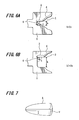
- the reason for setting the relationship between b and c to satisfy b ⁇ 2c is described with reference to FIGS. 6A and 6B .
- the first and second wires 61, 62 may have been aligned in the widthwise direction of the opening of the conductive wire winding portion 3. If the conductive wire 6 is wound around the conductive wire winding portion 3 in this manner, when the metal terminal 1 is compressed until the priority contact portions 5 contact each other in the subsequent compressing step, excessive compression stress is applied to the first and second conductive wires 61, 62, disconnection may be caused in the conductive wire 6.
- the compression processing time until the priority contact portions 5 contact each other increases. Further, the degree of deformation in the opening portion 2 increases, and the metal terminal 1 may be broken.
- the conductive wires 61, 62 may be wound around the conductive wire winding portion 3 with a large gap formed in the widthwise direction of the opening portion. In this state, even if the opening portion 2 is compression processed in the subsequent compression step, it may be difficult to reliably hold and fix the conductive wires 61, 62 to the conductive wire winding portion 3. Further, the compression time until the priority contact portions 5 contact each other increases and the degree of deformation in the opening portion 2 increases, so that the metal terminal 1 may be broken.
- the relationship between the width "b" in the widthwise direction of the opening of the conductive wire winding portion 3 and the diameter "c" of the conductive wire 6 to be wound around the conductive wire winding portion 3 is set to satisfy c ⁇ b ⁇ 2c.
- b approximately equals to 1.5c it is possible to increase degree of freedom in winding the conductive wire 6 around the conductive wire winding portion 3 when completing the step of winding the conductive wire. Further, the dimensional accuracy when the metal terminal 1 is produced by punching a phosphor bronze plate member can be made satisfactory.
- the long/short axis aspect ratio in this embodiment is defined as a value obtained by dividing a long axis dimension by a short axis dimension in an object A having a long axis x and a short axis y orthogonal to the long axis x.
- the long/short axis aspect ratio of an object having a round shape or equilateral quadrilateral shape is one
- the long/short axis aspect ratio of an object with the long axis x of two and the short axis y of 0.5 is four.
- Table 1 shows the results of the experiment.
- the long/short axis aspect ratio of the conductive wires that can secure reliability against blowout is in a range of 1 to 3.5.
- the initially wound conductive wire 61 is flattened less, and the secondary wound conductive wire 62 receives greater compression stress, so that the conductive wire 61 is flattened more than the second conductive wire 62.
- the long/short axis aspect ratio of the second conductive wire should be in a range of 1 to 3.5.
- the long/short axis aspect ratio of the conductive wire 62 should be set so as to be in a range of 1.5 to 3.5.
- the long/short axis aspect ratio of the conductive wire 62 wound outermost should be set so as to be in the range of 1.5 to 3.5.
- the deformed state of the conductive wire 62 is analogous to a shape of a bullet or a drop as illustrated in FIG. 8C .
- the length "a" in the lengthwise direction of the opening of the conductive wire winding portion 3 approximates a distance obtained by adding x1 and x2, where "x1" is defined as a distance between the contact points of the tangential lines connecting the conductive wires 61, 62 and an intersecting point of the two tangential lines, and "x2" is defined as a diameter of conductive wire 61.
- the length "a" in the lengthwise direction of the opening of the conductive wire winding portion 3 approximates 0.60 mm, which is obtained by adding 0.52 mm and 0. 085 mm. If the tolerance of ⁇ 0.1 mm that is presently conceivable is included, the length "a" in the lengthwise direction of the opening of the conductive wire winding portion 3 should be set in a range of 0.5 mm to 0.7 mm.
- the length "a" in the lengthwise direction of the opening of the conductive wire winding portion 3 approximates 0.80 mm, which is obtained by adding 0.70 mm and 0. 085 mm. If the tolerance of ⁇ 0.1 mm that is presently conceivable is considered, the length "a" in the lengthwise direction of the opening of the conductive wire winding portion 3 will be in a range of 0.7 mm to 0.9 mm. Consequently, the length "a" of the conductive wire winding portion 3 should be set in a range of 0.5 mm to 0.9 mm.
- the range of the length "a" in the lengthwise direction of the opening of the conductive wire winding portion 3 will be in a range of 0.5 mm to 0. 9 mm. Consequently, when the length "a” is computed based on the ratio of the length in the lengthwise direction of the opening of the conductive wire winding portion 3 with the diameter of the conductive wire 6 of approximately 0.17 mm obtained before being flattened, the range of the length "c" is approximately 3c ⁇ a ⁇ 5c.
- the relationship between the length "a” in the lengthwise direction of the opening of the conductive wire winding portion 3 and the diameter "c" of the conductive wire 6 to be wound around the conductive wire winding portion 3 is defined so as to satisfy 3c ⁇ a ⁇ 5c.
- the relationship between the length "a” in the lengthwise direction and the width "b” in the widthwise direction of the opening of the conductive wire winding portion 3 and the diameter "c" of the conductive wire 6 to be wound around the conductive wire winding portion 3 is prescribed so as to satisfy 3c ⁇ a ⁇ 5c and c ⁇ b ⁇ 2c.
- the conductive wire 62 having the long/short axis aspect ratio of 1.5 is preferable to use that the conductive wire 62 having the long/short axis aspect ratio of 1.5.
- the particularly preferable relationship between the length "a” in the lengthwise direction of the specifically preferable conductive wire winding portion 3 and the diameter "c" of the conductive wire 6 to be wound around the conductive wire winding portion 3 is in a range of 3c ⁇ a ⁇ 4.2c.
- the conductive wire 6 since the relationship between the length "a” in the lengthwise direction and the width "b” in the widthwise direction of the opening of the conductive wire winding portion 3 and the diameter "c" of the conductive wire 6 wound around the conductive wire winding portion 3 is set to satisfy 3c ⁇ a ⁇ 5, and c ⁇ b ⁇ 2c, the conductive wire 6 may not excessively be flattened when holding and fixing the conductive wire 6 to the metal terminal 1 in the subsequent compression step, so that breaking of the conductive wire 6 can be suppressed.
- the movement of the conductive wire 6 wound around the conductive wire winding portion 3 is regulated such that the conductive wires 61, 62 are regularly aligned, so that the fixing positions of the conductive wire 6 around the conductive wire winding portion 3 are uniform, thereby improving the quality of the metal terminal 1.
- the step terminates in the state that the priority contact portions 5 are preferentially brought into contact with each other to form the gap 7.
- the step terminates in the state that the priority contact portions 5 are preferentially brought into contact with each other to form the gap 7.
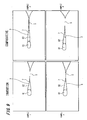
- FIG. 9 is a view illustrating comparison between the states of the cross sections of the conductive wires 61, 62 in the metal terminal 1 of the present embodiment and the states of the cross sections of the conductive wires 61, 62 in a metal terminal other than the metal terminal 1 of the present embodiment.
- Samples 1, 2 indicate the metal terminals of this embodiment, whereas samples 2, 3 indicate those of a comparative embodiment. Samples 1, 2 are manufactured so as to meet the same condition, and Samples 3, 4 are also manufactured so as to meet the same condition.
- the states of the conductive wires 61, 62 are approximately the same after compression processing. Specifically, the compressed degree and contact areas of the conductive wires 61, 62 are also approximately the same. Further, the sizes of the gaps 7 formed in the conductive wire winding portion 3 are also approximately the same.
- FIG. 2A is a schematic view illustrating an metal terminal component 9 having the metal terminal 1, during production, and illustrates a state immediately after processing a phosphor bronze plate by punching and in which the metal terminal component 9 is connected with a frame 12. Note that the same reference numerals are provided for components in FIG. 2A that are identical to those shown in FIG. 1 , and description thereof is thus omitted.
- the metal terminal component 9 includes the metal terminal 1 having the opening portion 2 for winding the aforementioned conductive wire 6 around the conductive wire winding portion 3, and an input-output terminal 8.
- the input-output terminal 8 includes a planer portion formed therein, thus enabling connection of lead terminals/lead pins (not shown) and electrical connection of coil components to external electric circuits/electric devices as well.
- the metal terminal 1 and the input-output terminal 8 forming the metal terminal component 9 are separated from the frame 12 by cut processing, or the like, both of which are then respectively implanted in a resin base bobbin 11.
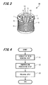
- FIG. 3 is an overall view illustrating a coil component 10 that includes the metal terminal component 9 having the metal terminal 1. Note that the same reference numerals are provided for the components in FIG. 3 which are identical to those shown in FIG. 2A , and description thereof is thus omitted.
- the coil component 10 of the embodiment includes the resin base bobbin 11 having a winding spindle with an air-core portion 13, the conductive wire 6 wound around the winding spindle, the metal terminal 1 implanted in the resin base bobbin 11, and lead pins 14 connected to the input-output terminal 8.
- An end portion of the conductive wire 6 forming the coil is wound around the conductive wire winding portion 3 of the metal terminal 1 of the metal terminal component 9 and is held and fixed to the metal terminal 1.
- the fixing position of the conductive wire 6 held and fixed to the metal terminal 1 are made uniform, so that even when the coil component 10 is mass-produced, the product quality can be maintained.
- FIG. 4 is a flow-chart illustrating a manufacturing step for holding and fixing the conductive wire 6 to the metal terminal 1.
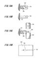
- FIGS. 5A, 5B, 5C, 5D are views illustrating the states of the metal terminal and the conductive wire deforming according to the flow-chart of the manufacturing steps. Note that the method for holding and fixing a conductive wire to the metal terminal of the invention is not limited to the embodiment described below.
- step 1 when holding and fixing the conductive wire 6 to the metal terminal 1, the steps of winding (step 1), compression-processing (step 2), and welding (step 3) the conductive wire are included.
- step S1 the conductive wire 6 extending from the wound coil, not shown, is wound a plurality of times (about twice in this example) around the opening portion 2 having a crocodile's jaws-shape the metal terminal 1.
- the conductive wire 6 can be wound around the metal terminal 1 without slack while applying tensile force to the conductive wire 6 in the direction indicated by an arrow in FIG. 5A .
- step S2 the compression-processing is performed bringing a compression tool 20 into contact with a predetermined area 1a of the metal terminal 1 until the priority contact portions 5 are in contact with each other.
- the reason of bringing the compression tool 20 into contact with the predetermined area 1a the metal terminal 1 is that only the opening portion 2 having the crocodile's jaws-shape can be deformed by minimum necessary pressure, while obtaining the cost-efficiency in the mass production environment. Since only the opening portion 2 is deformed and adequate gap 7 can be formed as illustrated in FIG. 5C by bringing into contact with each other first, the conductive wire 6 can be prevented from being excessively flattened.
- the compression-processing step can terminate at a point where the priority contact portions 5 have contacted each other and the pressure has increased.
- step S3 as shown in FIG 5D , after the compression step (step 2) described above, a welding electrode 21 is brought into contact with the predetermined area of the metal terminal 1 so as to weld the conductive wire 6 and the metal terminal 1. As described above, through steps S1 to S3, the step of holding and fixing the conductive wire 6 to the metal terminal 1 is thus completed.
- the adequate gap 7 can be formed in the conductive wire winding portion 3 with synergistic factors of the step of winding the conductive wire around the opening portion 2 having the conductive wire winding portion 3, the conductive wire introducing portion 4, and the priority contact portions 5 while applying tensile force to the conductive wire 6 in a predetermined direction; and the compressing step of bringing the compression tool into contact with to the predetermined area of the metal terminal and applying pressure until the priority contact portions contact each other.
- the conductive wire 6 wound can be prevented from being flattened excessively, thereby decreasing the frequency of breaking the conductive wire 6 wound around the metal terminal 1.
- the movement of the conductive wire 6 around the conductive wire winding portion 3 is regulated such that the conductive wires 61, 62 are regularly aligned, the fixing positions of the conductive wire 6 wound around the conductive wire winding portion 3 are made uniform, thereby improving the quality of the product.
- an effect of constant heat conductivity can be obtained in a subsequent welding step, and the conductive wire 6 can simply and securely be held and fixed to the metal terminal 1.
Landscapes
- Engineering & Computer Science (AREA)
- Power Engineering (AREA)
- Manufacturing & Machinery (AREA)
- Connections Effected By Soldering, Adhesion, Or Permanent Deformation (AREA)
- Coils Of Transformers For General Uses (AREA)
- Coils Or Transformers For Communication (AREA)
Applications Claiming Priority (2)
| Application Number | Priority Date | Filing Date | Title |
|---|---|---|---|
| JP2006067798 | 2006-03-13 | ||
| PCT/JP2007/053315 WO2007105451A1 (ja) | 2006-03-13 | 2007-02-22 | 金属端子、コイル部品及び導電線の保持固定方法 |
Publications (1)
| Publication Number | Publication Date |
|---|---|
| EP2006865A1 true EP2006865A1 (de) | 2008-12-24 |
Family
ID=38509288
Family Applications (1)
| Application Number | Title | Priority Date | Filing Date |
|---|---|---|---|
| EP07714812A Withdrawn EP2006865A1 (de) | 2006-03-13 | 2007-02-22 | Metallanschluss, spulenkomponente und halte- und fixierverfahren |
Country Status (6)
| Country | Link |
|---|---|
| US (1) | US20090039997A1 (de) |
| EP (1) | EP2006865A1 (de) |
| JP (1) | JPWO2007105451A1 (de) |
| CN (1) | CN101371320A (de) |
| TW (1) | TW200746569A (de) |
| WO (1) | WO2007105451A1 (de) |
Cited By (1)
| Publication number | Priority date | Publication date | Assignee | Title |
|---|---|---|---|---|
| WO2016112937A1 (de) * | 2015-01-14 | 2016-07-21 | Audi Ag | Verfahren zum bewickeln eines wicklungsträgers |
Families Citing this family (4)
| Publication number | Priority date | Publication date | Assignee | Title |
|---|---|---|---|---|
| JP5234033B2 (ja) * | 2010-03-18 | 2013-07-10 | 株式会社デンソー | 電源装置 |
| TWI490488B (zh) * | 2013-03-29 | 2015-07-01 | Nat Inst Chung Shan Science & Technology | 拋棄式線材輔助夾具 |
| TWM471092U (zh) * | 2013-10-21 | 2014-01-21 | 帛漢股份有限公司 | 電子元件座 |
| CN110224536B (zh) * | 2018-03-02 | 2024-03-22 | 日本电产三协电子(东莞)有限公司 | 电机 |
Family Cites Families (5)
| Publication number | Priority date | Publication date | Assignee | Title |
|---|---|---|---|---|
| JPH0310644Y2 (de) * | 1981-04-16 | 1991-03-15 | ||
| DE3404008A1 (de) | 1984-02-06 | 1985-08-08 | Robert Bosch Gmbh, 7000 Stuttgart | Verfahren zum befestigen von metalldraehten an metallischen anschlusstraegern |
| DE4332172A1 (de) * | 1993-09-22 | 1995-03-23 | Bosch Gmbh Robert | Anschlußträger und Verfahren zum Herstellen von metallischen Anschlußträgern bzw. zum Befestigen von Metalldrähten an Anschlußträgern |
| JP2004179498A (ja) * | 2002-11-28 | 2004-06-24 | Minebea Co Ltd | コイルボビン構造 |
| JP2004342474A (ja) * | 2003-05-16 | 2004-12-02 | Nidec Tosok Corp | 端子構造 |
-
2007
- 2007-02-22 EP EP07714812A patent/EP2006865A1/de not_active Withdrawn
- 2007-02-22 US US12/282,639 patent/US20090039997A1/en not_active Abandoned
- 2007-02-22 JP JP2008505029A patent/JPWO2007105451A1/ja active Pending
- 2007-02-22 CN CNA2007800024606A patent/CN101371320A/zh active Pending
- 2007-02-22 WO PCT/JP2007/053315 patent/WO2007105451A1/ja not_active Ceased
- 2007-03-07 TW TW096107864A patent/TW200746569A/zh unknown
Non-Patent Citations (1)
| Title |
|---|
| See references of WO2007105451A1 * |
Cited By (1)
| Publication number | Priority date | Publication date | Assignee | Title |
|---|---|---|---|---|
| WO2016112937A1 (de) * | 2015-01-14 | 2016-07-21 | Audi Ag | Verfahren zum bewickeln eines wicklungsträgers |
Also Published As
| Publication number | Publication date |
|---|---|
| JPWO2007105451A1 (ja) | 2009-07-30 |
| WO2007105451A1 (ja) | 2007-09-20 |
| TW200746569A (en) | 2007-12-16 |
| US20090039997A1 (en) | 2009-02-12 |
| CN101371320A (zh) | 2009-02-18 |
Similar Documents
| Publication | Publication Date | Title |
|---|---|---|
| DE69026188T2 (de) | Elektrischer Verbinder | |
| KR101221744B1 (ko) | 단자 커넥터 및 단자 커넥터를 구비한 전선 | |
| EP2006865A1 (de) | Metallanschluss, spulenkomponente und halte- und fixierverfahren | |
| US11143674B2 (en) | Probe head with linear probe | |
| US10276283B2 (en) | Manufacturing method for terminal-equipped electric wire | |
| JP7505605B2 (ja) | コンデンサの製造方法 | |
| US20170331243A1 (en) | Wire with terminal and manufacturing method therefor | |
| KR20210054534A (ko) | 바람직하게는 구리에 기반하며 소량의 납을 함유하는 개선된 재료로 구성된 컴포넌트들을 가진 플러그인 커넥터 | |
| WO2009147754A1 (ja) | スプライス接続電線及びスプライス接続電線の製造方法 | |
| US12584945B2 (en) | Contact probe and socket for electrical component testing | |
| US20160308297A1 (en) | Spring connector | |
| CN110918822A (zh) | 端子折弯装置、端子折弯方法和线圈部件的制造方法 | |
| US12095183B2 (en) | Press-fit terminal and method for producing press-fit terminal | |
| EP3685479B1 (de) | Litzenkontakt für ein elektrisches bauelement und verfahren zur herstellung eines litzenkontakts | |
| US6960729B2 (en) | Upright-pin-joined resin substrate, method of producing the substrate, pins, and method of producing the pins | |
| CN102341973B (zh) | 将线固定于连接元件的装置 | |
| US6442834B1 (en) | Method of manufacture substrate-use terminals | |
| DE102006025661B4 (de) | Kontaktklemme zum Anschließen eines Litzenleiters an einen relativ dünnen Anschlussstift | |
| JPH11273818A (ja) | 半導体素子検査用ソケットのコンタクト | |
| JP2532427B2 (ja) | 電子部品のリ−ド曲げ形成方法及び装置 | |
| JPH05166561A (ja) | ピンコンタクトおよびその製造方法 | |
| DE102022117760B3 (de) | Elektrisches Kontaktelement | |
| CN111786135A (zh) | 开翼式接线端子 | |
| DE202006008713U1 (de) | Kontaktklemme zum Anschließen eines Litzenleiters an einen relativ dünnen Anschlussstift | |
| WO2025040722A1 (de) | Sensorbaugruppe und verfahren zur herstellung einer sensorbaugruppe |
Legal Events
| Date | Code | Title | Description |
|---|---|---|---|
| PUAI | Public reference made under article 153(3) epc to a published international application that has entered the european phase |
Free format text: ORIGINAL CODE: 0009012 |
|
| 17P | Request for examination filed |
Effective date: 20081010 |
|
| AK | Designated contracting states |
Kind code of ref document: A1 Designated state(s): DE FR GB IT |
|
| DAX | Request for extension of the european patent (deleted) | ||
| RBV | Designated contracting states (corrected) |
Designated state(s): DE FR GB IT |
|
| STAA | Information on the status of an ep patent application or granted ep patent |
Free format text: STATUS: THE APPLICATION HAS BEEN WITHDRAWN |
|
| 18W | Application withdrawn |
Effective date: 20100316 |