EP2006961A1 - Installation destinée à la liaison électrique d'un premier système de raccordement à un second - Google Patents
Installation destinée à la liaison électrique d'un premier système de raccordement à un second Download PDFInfo
- Publication number
- EP2006961A1 EP2006961A1 EP07009469A EP07009469A EP2006961A1 EP 2006961 A1 EP2006961 A1 EP 2006961A1 EP 07009469 A EP07009469 A EP 07009469A EP 07009469 A EP07009469 A EP 07009469A EP 2006961 A1 EP2006961 A1 EP 2006961A1
- Authority
- EP
- European Patent Office
- Prior art keywords
- connection means
- bristles
- assembly
- automation device
- protective cover
- Prior art date
- Legal status (The legal status is an assumption and is not a legal conclusion. Google has not performed a legal analysis and makes no representation as to the accuracy of the status listed.)
- Withdrawn
Links
- 230000001681 protective effect Effects 0.000 claims description 17
- 239000002184 metal Substances 0.000 claims 3
- 208000027418 Wounds and injury Diseases 0.000 description 3
- 230000006378 damage Effects 0.000 description 3
- 208000014674 injury Diseases 0.000 description 3
- XAGFODPZIPBFFR-UHFFFAOYSA-N aluminium Chemical compound [Al] XAGFODPZIPBFFR-UHFFFAOYSA-N 0.000 description 2
- 229910052782 aluminium Inorganic materials 0.000 description 2
- 238000003780 insertion Methods 0.000 description 2
- 230000037431 insertion Effects 0.000 description 2
- 230000032683 aging Effects 0.000 description 1
- 238000005452 bending Methods 0.000 description 1
- 230000015572 biosynthetic process Effects 0.000 description 1
- 238000011109 contamination Methods 0.000 description 1
- 230000001419 dependent effect Effects 0.000 description 1
- 230000006866 deterioration Effects 0.000 description 1
- 230000007774 longterm Effects 0.000 description 1
- 230000013011 mating Effects 0.000 description 1
Images


Classifications
-
- H—ELECTRICITY
- H01—ELECTRIC ELEMENTS
- H01R—ELECTRICALLY-CONDUCTIVE CONNECTIONS; STRUCTURAL ASSOCIATIONS OF A PLURALITY OF MUTUALLY-INSULATED ELECTRICAL CONNECTING ELEMENTS; COUPLING DEVICES; CURRENT COLLECTORS
- H01R39/00—Rotary current collectors, distributors or interrupters
- H01R39/02—Details for dynamo electric machines
- H01R39/18—Contacts for co-operation with commutator or slip-ring, e.g. contact brush
- H01R39/24—Laminated contacts; Wire contacts, e.g. metallic brush, carbon fibres
-
- H—ELECTRICITY
- H01—ELECTRIC ELEMENTS
- H01R—ELECTRICALLY-CONDUCTIVE CONNECTIONS; STRUCTURAL ASSOCIATIONS OF A PLURALITY OF MUTUALLY-INSULATED ELECTRICAL CONNECTING ELEMENTS; COUPLING DEVICES; CURRENT COLLECTORS
- H01R39/00—Rotary current collectors, distributors or interrupters
- H01R39/02—Details for dynamo electric machines
- H01R39/38—Brush holders
- H01R39/381—Brush holders characterised by the application of pressure to brush
-
- H—ELECTRICITY
- H01—ELECTRIC ELEMENTS
- H01R—ELECTRICALLY-CONDUCTIVE CONNECTIONS; STRUCTURAL ASSOCIATIONS OF A PLURALITY OF MUTUALLY-INSULATED ELECTRICAL CONNECTING ELEMENTS; COUPLING DEVICES; CURRENT COLLECTORS
- H01R9/00—Structural associations of a plurality of mutually-insulated electrical connecting elements, e.g. terminal strips or terminal blocks; Terminals or binding posts mounted upon a base or in a case; Bases therefor
- H01R9/22—Bases, e.g. strip, block, panel
- H01R9/24—Terminal blocks
Definitions
- the invention relates to an arrangement for electrically connecting a first and a second connection means.
- the invention relates to an automation device according to the preamble of claim 8 and further relates to an assembly according to the preamble of claim 15, which is suitable for connection to such an automation device.
- an automation device which has a plurality of modules and a rack.
- the rack is provided for receiving the modules and for supplying them with an operating voltage, wherein the modules can be plugged into slots of a backplane bus, via which the modules are interconnected.
- Each slot of the rack has three parallel arranged and provided with a ground potential spring contacts on one edge, which are electrically connected to a terminal of a plug-in module.
- the present invention has for its object to provide an arrangement of the type mentioned, which allows improved contacting of the connection means. Furthermore, an automation device of the aforementioned Specify type with an improved contacting of the module with an electrical potential of the rack of the programmable controller. In addition, an assembly of the aforementioned type is to be created, which is suitable for use in such an automation device.
- the bristle connection means are designed as brushes which in various forms, for. B. in the form of round, pot or cone brushes, or may be formed in any other suitable form.
- a simple or in the case of a wave-shaped formation of the bristles a very good contact with regard to the number of possible contact points is achieved. If the connection means are put together, the bristles interlock and hook one another.
- the bristles are formed like velcro, whereby the contacting of the bristles is further improved.
- the bristles of both connection means have to check at their ends, the when mating the connection means interlock.
- the ends of the bristles of only one connection means with hooks and the ends of the bristles of the second connection means can also be provided with loops.
- the first and / or the second connection means are formed as a bristle rail.
- a bristle rail is suitable for use in a rack of an automation device as ground potential rail.
- connection means for protecting the bristles is provided with a protective casing or a protective housing, prevents the bristles are bent too much. In addition, it is ensured that the risk of injury to a user is essentially excluded.
- the protective cover of the connection means is designed to be axially movable with respect to the bristles. If the connection means plugged in, the protective sheath moves against the direction of insertion. Upon release of the connection means, the protective sheath shifts over the bristles, whereby the bristles, which have bent too much during the insertion, essentially bend straight again.
- FIG. 5 a known subrack 1 of an automation device is shown.
- Components of this subrack 1 are an aluminum support 2, two mounted on this support 2 bus circuit boards 3 and a plastic support 4, through the openings 5 plug-in terminals 6 of the bus circuit boards 3 to the connection side of the rack 1 protrude.
- only one assembly 7 is shown, which is mounted on one of the plug-in terminals 6.
- the aluminum support 2 is provided with two ground potential rails 8, to which electrically conductive, resilient contact parts 9 are mounted, which are guided through further openings 10 of the plastic carrier 4. These contact parts 9 contact with connection means of the inserted module 7, whereby this module 7 is connected to the ground potential.
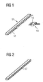
- a bristle rail 11 ( FIG. 1 ) has a plurality of electrically conductive bristles 12, which are contacted with a likewise having a plurality of electrically conductive bristles 13 having brush 14 of a module.
- the bristle rail 11 need not necessarily be formed with standing bristles; it is also possible to design these as bristle braid 17 ( FIG. 2 ).
- the bristle rail 11 and the brush 14 have protective sheaths 15, 16, of which the Protective cover 15 of the brush rail 11 rigid and the protective cover of the brush 14 is designed to be movable ( FIGS. 3 and 4 ).
- the protective sheath 16 shifts in the opposite direction.
- the protective cover 15 limits the bending of the bristles 12, 13 at right angles to the sliding direction.
- the protective cover 16 pushes back over the bristles 13 of the brush 14, whereby the bristles 13 are not accessible to a user and thus the risk of injury is largely excluded.
- connection means 11, 14 are formed with a plurality of electrically conductive bristles 12, 13. In the event that the requirements for good contact are not so high, it is sufficient to provide only one connection means with a plurality of bristles.
- the other connection means may in this case be a metallic rail, an inclined wall or a tube.
Landscapes
- Elimination Of Static Electricity (AREA)
Priority Applications (1)
| Application Number | Priority Date | Filing Date | Title |
|---|---|---|---|
| EP07009469A EP2006961A1 (fr) | 2007-05-11 | 2007-05-11 | Installation destinée à la liaison électrique d'un premier système de raccordement à un second |
Applications Claiming Priority (1)
| Application Number | Priority Date | Filing Date | Title |
|---|---|---|---|
| EP07009469A EP2006961A1 (fr) | 2007-05-11 | 2007-05-11 | Installation destinée à la liaison électrique d'un premier système de raccordement à un second |
Publications (1)
| Publication Number | Publication Date |
|---|---|
| EP2006961A1 true EP2006961A1 (fr) | 2008-12-24 |
Family
ID=38544223
Family Applications (1)
| Application Number | Title | Priority Date | Filing Date |
|---|---|---|---|
| EP07009469A Withdrawn EP2006961A1 (fr) | 2007-05-11 | 2007-05-11 | Installation destinée à la liaison électrique d'un premier système de raccordement à un second |
Country Status (1)
| Country | Link |
|---|---|
| EP (1) | EP2006961A1 (fr) |
Citations (4)
| Publication number | Priority date | Publication date | Assignee | Title |
|---|---|---|---|---|
| EP0236711A2 (fr) * | 1986-02-06 | 1987-09-16 | Siemens Aktiengesellschaft | Appareil d'automatisation |
| US5774341A (en) | 1995-12-20 | 1998-06-30 | Motorola, Inc. | Solderless electrical interconnection including metallized hook and loop fasteners |
| US20050040602A1 (en) | 2003-08-18 | 2005-02-24 | Mtu Aero Engines Gmbh | Brush seal |
| GB2425294A (en) | 2005-04-20 | 2006-10-25 | Clayton Comm Ltd | Trolley battery charging arrangement |
-
2007
- 2007-05-11 EP EP07009469A patent/EP2006961A1/fr not_active Withdrawn
Patent Citations (4)
| Publication number | Priority date | Publication date | Assignee | Title |
|---|---|---|---|---|
| EP0236711A2 (fr) * | 1986-02-06 | 1987-09-16 | Siemens Aktiengesellschaft | Appareil d'automatisation |
| US5774341A (en) | 1995-12-20 | 1998-06-30 | Motorola, Inc. | Solderless electrical interconnection including metallized hook and loop fasteners |
| US20050040602A1 (en) | 2003-08-18 | 2005-02-24 | Mtu Aero Engines Gmbh | Brush seal |
| GB2425294A (en) | 2005-04-20 | 2006-10-25 | Clayton Comm Ltd | Trolley battery charging arrangement |
Similar Documents
| Publication | Publication Date | Title |
|---|---|---|
| EP0527247B1 (fr) | Bus se construisant automatiquement | |
| DE2843858A1 (de) | Sammelschienensystem zum anschliessen von elektrischen installationseinbaugeraeten | |
| EP0909122B1 (fr) | Appareil électrique | |
| DE3546712C2 (fr) | ||
| DE102007053535A1 (de) | Verbindungsmodul und Schaltgerät mit einem Verbindungsmodul | |
| DE202015106730U1 (de) | Stecker für Durchgangsverdrahtung | |
| DE19618958A1 (de) | Modulare Bürsteneinsteckkassette | |
| DE2251020C3 (de) | Anschlußvorrichtung | |
| DE3103455C2 (de) | Elektrischer Steckverbinder, insbesondere der Datentechnik | |
| DE29813707U1 (de) | Schirmabführung bei modularen Steuerungen direkt am Konaktpunkt | |
| EP1717931A2 (fr) | Dispositif interrupteur de moteur pour un outil portatif | |
| EP1462808B1 (fr) | Dispositif de connexion pour un compteur d'électricité | |
| EP2006961A1 (fr) | Installation destinée à la liaison électrique d'un premier système de raccordement à un second | |
| DE102019121165A1 (de) | System zur Realisierung einer Leuchte mit elektrischem Abgriff mit Leiterhalter | |
| DE19610037C2 (de) | Baugruppenträger | |
| EP3885648B1 (fr) | Système de fourniture d'un luminaire pourvu de branchement électrique comprenant un dispositif contact traversant | |
| DE202008004766U1 (de) | Codierbare Motoranschlusssteckkupplung | |
| DE102009007956B4 (de) | Umrichter | |
| EP2073314B1 (fr) | Agencement de liaison électrique conductrice des conducteurs électriques | |
| DE102008033159B3 (de) | Anordnung mit einer elektrischen Strom- oder Potentialschiene | |
| DE102019134359B4 (de) | Ordnungssystem für Anschlussleitungen | |
| DE202019004071U1 (de) | Elektrisches Gerät | |
| DE19532280A1 (de) | Anschlußvorrichtung zum codierbaren Anschließen elektrischer Verbraucher | |
| DE4237865C2 (de) | Baugruppenträger | |
| DE10334071B4 (de) | Steckverbindungssystem mit integrierter Verriegelung |
Legal Events
| Date | Code | Title | Description |
|---|---|---|---|
| PUAI | Public reference made under article 153(3) epc to a published international application that has entered the european phase |
Free format text: ORIGINAL CODE: 0009012 |
|
| 17P | Request for examination filed |
Effective date: 20080312 |
|
| AK | Designated contracting states |
Kind code of ref document: A1 Designated state(s): AT BE BG CH CY CZ DE DK EE ES FI FR GB GR HU IE IS IT LI LT LU LV MC MT NL PL PT RO SE SI SK TR |
|
| AX | Request for extension of the european patent |
Extension state: AL BA HR MK RS |
|
| AKX | Designation fees paid |
Designated state(s): DE FR GB IT |
|
| RAP1 | Party data changed (applicant data changed or rights of an application transferred) |
Owner name: SIEMENS AKTIENGESELLSCHAFT |
|
| GRAP | Despatch of communication of intention to grant a patent |
Free format text: ORIGINAL CODE: EPIDOSNIGR1 |
|
| RIC1 | Information provided on ipc code assigned before grant |
Ipc: H01R 39/38 20060101ALI20161011BHEP Ipc: H01R 39/24 20060101ALI20161011BHEP Ipc: H01R 9/24 20060101AFI20161011BHEP |
|
| INTG | Intention to grant announced |
Effective date: 20161104 |
|
| STAA | Information on the status of an ep patent application or granted ep patent |
Free format text: STATUS: THE APPLICATION IS DEEMED TO BE WITHDRAWN |
|
| RAP1 | Party data changed (applicant data changed or rights of an application transferred) |
Owner name: SIEMENS AKTIENGESELLSCHAFT |
|
| 18D | Application deemed to be withdrawn |
Effective date: 20170315 |