EP2006982A2 - Procédés pour la fabrication d'actionneurs de superposition de couple - Google Patents
Procédés pour la fabrication d'actionneurs de superposition de couple Download PDFInfo
- Publication number
- EP2006982A2 EP2006982A2 EP08158443A EP08158443A EP2006982A2 EP 2006982 A2 EP2006982 A2 EP 2006982A2 EP 08158443 A EP08158443 A EP 08158443A EP 08158443 A EP08158443 A EP 08158443A EP 2006982 A2 EP2006982 A2 EP 2006982A2
- Authority
- EP
- European Patent Office
- Prior art keywords
- torque
- teeth
- steering system
- tooth
- pole
- Prior art date
- Legal status (The legal status is an assumption and is not a legal conclusion. Google has not performed a legal analysis and makes no representation as to the accuracy of the status listed.)
- Granted
Links
Images


Classifications
-
- B—PERFORMING OPERATIONS; TRANSPORTING
- B62—LAND VEHICLES FOR TRAVELLING OTHERWISE THAN ON RAILS
- B62D—MOTOR VEHICLES; TRAILERS
- B62D5/00—Power-assisted or power-driven steering
- B62D5/06—Power-assisted or power-driven steering fluid, i.e. using a pressurised fluid for most or all the force required for steering a vehicle
- B62D5/08—Power-assisted or power-driven steering fluid, i.e. using a pressurised fluid for most or all the force required for steering a vehicle characterised by type of steering valve used
- B62D5/083—Rotary valves
- B62D5/0835—Rotary valves characterised by means for actively influencing the deflection angle of the valve, e.g. depending on driving parameters
-
- H—ELECTRICITY
- H02—GENERATION; CONVERSION OR DISTRIBUTION OF ELECTRIC POWER
- H02K—DYNAMO-ELECTRIC MACHINES
- H02K49/00—Dynamo-electric clutches; Dynamo-electric brakes
- H02K49/06—Dynamo-electric clutches; Dynamo-electric brakes of the synchronous type
-
- H—ELECTRICITY
- H02—GENERATION; CONVERSION OR DISTRIBUTION OF ELECTRIC POWER
- H02K—DYNAMO-ELECTRIC MACHINES
- H02K2213/00—Specific aspects, not otherwise provided for and not covered by codes H02K2201/00 - H02K2211/00
- H02K2213/03—Machines characterised by numerical values, ranges, mathematical expressions or similar information
-
- Y—GENERAL TAGGING OF NEW TECHNOLOGICAL DEVELOPMENTS; GENERAL TAGGING OF CROSS-SECTIONAL TECHNOLOGIES SPANNING OVER SEVERAL SECTIONS OF THE IPC; TECHNICAL SUBJECTS COVERED BY FORMER USPC CROSS-REFERENCE ART COLLECTIONS [XRACs] AND DIGESTS
- Y10—TECHNICAL SUBJECTS COVERED BY FORMER USPC
- Y10T—TECHNICAL SUBJECTS COVERED BY FORMER US CLASSIFICATION
- Y10T29/00—Metal working
- Y10T29/49—Method of mechanical manufacture
- Y10T29/49462—Gear making
- Y10T29/49467—Gear shaping
Definitions
- This invention relates generally to vehicle steering devices, and more particularly, this invention relates to vehicle steering devices for controlling torque.
- a pull condition can occur in which a driver of the vehicle has to input torque into the steering system in order to maintain a straight path.
- This condition can be caused by vehicle and road conditions and weather conditions such as a crosswind that require a force for the steering system to overcome, or by an imbalance in the steering system (such as if the valve is balanced in the null position and the torsion bar is on center but the valve spool is creating pressure in the system) which requires an input torque by the driver to correct.
- Various designs are known for controlling input torque.
- One design includes the use of cogs in steering mechanisms.
- Cogging torque has significant influence on the output torque profile of torque overlay (TO) actuators. For example, due to interactions of a permanent magnet with teeth of a cog, cogging or detent torque is caused. Cogging torque can be minimized using conventional methods, such as by providing skew (in at least one of the permanent magnet and teeth of the cog), a dummy notch in each of the teeth or selected teeth, and by shifting of the permanent magnet or teeth. For a permanent magnet having a ring design, including skew is a simple design around.
- FIG. 1A and FIG. 1B depict torque angle plots showing torque versus angle for a torque overlay (TO) actuator ( FIG. 1A ) and a variable effort steering (VES) actuator;
- TO torque overlay
- VES variable effort steering
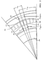
- FIG. 2 depicts teeth and pole shaping for desired cogging torque for an 18-pole, 9-teeth an n/2 design
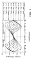
- FIG. 3 depicts cogging torque variation as a function of varying Ratio_Ang ;
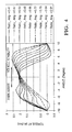
- FIG. 4 depicts variation of torque as a function of varying Ratio_Ang ;
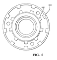
- FIG. 5 depicts an exemplary embodiment of an 18-pole, 9-teeth design as an n/2 design
- a torque-angle plot is shown at top for a torque overlay (TO) actuator and at bottom for variable effort steering (VES) actuator.
- TO torque overlay
- VES variable effort steering
- the hydraulic valves fully actuate at +/- 4 degrees.
- the valve profile is given as pressure-angle and the actuator output is given as torque-angle. Combined, they generate an effort curve that is pressure-torque.
- the angular displacement is +/-4 degrees maximum which is denoted by +/- ⁇ op in the diagram. This range can typically vary from +/-1 to +/-8 degrees and depends on the pressure angle profile of the hydraulic valves.
- a VES actuator can be clocked to operate as a TO actuator.
- cogging torque is not ideal in shape and does not provide full capability for park assist and vehicle stability. Within the operating range, the cogging torque is high, which is not desirable when no current fault condition happens.
- FIG. 1 shows the difference between desirable cogging torques in TO and VES actuators.
- the teachings herein define design bases for electromagnetic implementations used for obtaining the desired cogging torque for torque overly actuators in comparison to the variable effort steering actuators. Consider aspects of performance requirements for torque overlay actuators.
- cogging torque shown in FIG. 1A may be adequate for satisfying all of the characteristics mentioned above.
- Zero, or nearly zero, cogging torque is desirable within the operating range. This makes the curve for the torque flat or of a small slope.
- a nearly constant torque output also helps to reduce the controller burden to adjust current continuously to maintain the torque constant. Moving the cogging peaks from the symmetrical position helps to increase the peak torque at the comers.
- the cogging torque should be zero, or nearly zero, around the zero position of the torque overlay actuator for at least +/-2 degrees. Contrary to the zero position of the variable effort steering actuator, the torque overlay actuator has torque available with current at a zero position. This helps to meet the on center or around on center torque demand as needed and makes the torque flat or nearly constant.
- FIG. 2 is a partially cut-away drawing of an exemplary embodiment of a torque overlay actuator illustrating characteristics and relationships of portions of the torque overlay actuator.
- the torque overlay actuator includes an inner tooth 202 having a tooth width (TW IT ), a tooth depth (IT DEPTH ), and corners 210.
- An outer tooth 204 includes a tooth width (TW OT ), a tooth depth (OT DEPTH ), and corners 212.
- An interpolar zone is partially defined by the first pole portion 206 and the second pole portion 208.
- Tooth profiling may be performed to achieve the desired cogging shape in a manner similar to profiling for VES actuators. Shaping of magnetic poles may be used along with the other techniques.
- An important design parameter is the ratio between ⁇ tp / ⁇ mp , which is denoted here as Ratio_Ang.
- Ratio_Ang is the primary design parameter that guides the electromagnetic design for torque overlay or a variable effort steering actuator.
- a cogging torque profile may be determined.
- Cogging torque may be profiled by varying the design parameter Ratio_Ang as mentioned above.
- FIG. 3 and FIG. 4 show the zero degree as the zero position of the TO actuator.
- FIG. 3 shows how the cogging torque changes its shape and polarity by varying Ratio_Ang for a symmetric design
- the primary parameters that influences the cogging torque significantly are:
- ⁇ tp determines the teeth width.
- ⁇ mp is determined primarily by the number of poles.
- the effective polar width is further defined by the magnetization fixture which defines its inter-polar zone.
- Fig. 3 shows the suitable designs for TO actuators when Ratio_Ang is around 0.5 as an example for 18-pole 9-teeth design. Designs variations can be made by putting emphasis on either park assist or vehicle stability regions and the Ratio_Ang can be selected as needed.
- Fine tuning in the profile may be performed by putting corner radius on the tooth.
- the corner radius may be configured in any pattern. A non-limiting example is shown in FIG. 2 where the radius is present only in the inner side of the teeth pair.
- the corners may be sharp.
- the corners may include corner radius in both sides of the teeth or the inner side may have sharp and the outer side may have radius.
- the size of the radius can be adjusted to influence the cogging torque. Instead of radius, a tapered shape can also have similar effect on the cogging torque.
- the cogging torque also depends on the radial depth of the teeth.
- cogging torque also depends on the magnet strength, magnetization pattern and the airgap between magnet and teeth.
- the magnetization fixture can be used to control the magnet pole patterns.
- the magnets can be either radial oriented ring magnet or discrete arc or flat shaped (rectangular, square etc) magnets. For large number of poles, the ring magnet has an advantage of ease manufacturing.
- the inter-polar zone between each pole of the magnet can also be used to reshape the cogging torque.
- the teeth can be grouped together with ⁇ tp adjusted to shape the cogging torque.
- the teeth can be grouped in 2 or 3 or even more depending on the number of teeth.
- 18-pole 9-teeth design can be grouped in 1 or 3 and a 30-pole 15-tooth design can be grouped in 3 or 5.
- the grouping of multiple teeth is called n/4 or n/6 design where n is the number of poles.
- the design without any grouping is called n/2 design.
- the outer and inner tooth height and tooth width can be adjusted to reshape the cogging torque also.
- Ratio_Ang should be around 0.5 for best performing TO actuators, as it approximates the desired torque shape as shown in FIG. 1A .
- tooth width, tooth depth and corner radius are the additional options to further reshaping the cogging torque.
- the successful designs show the cogging torque peak to be outside the range of travel.
- Fig. 3 and Fig. 4 show the variation with respect to the parameter Ratio_Ang. It is possible to change the shape and polarity of cogging by using Ratio_Ang appropriately.
- n/4 design is a derivative of n/2 designs where grouping of multiple teeth is performed.
- exemplary rules for forming the groups include:
- the above provides additional control parameters to shape the cogging torque.
- the angular spacing among the teeth in each group as well as the angular spacing among different groups can be controlled to achieve the desired cogging shape.
- Tooth profiling within a group is still a design option.
- the embodiment is an 18-pole 9-teeth design where n equals 18 and k equals 9.
- the teeth may be grouped together. Accordingly, the design guidelines presented herein for determining Ratio_Ang provided for improved control of cogging torque.
- An exemplary embodiment is depicted in FIG. 5 .
- each tooth has radius in both corners for inner teeth 502 and outer teeth 504.
- FIG. 6 shows the effect of corner radius on torque and cogging torque. Corner radius or tapering may also be used for profiling the torque waveform.
Landscapes
- Engineering & Computer Science (AREA)
- Power Engineering (AREA)
- Chemical & Material Sciences (AREA)
- Combustion & Propulsion (AREA)
- Transportation (AREA)
- Mechanical Engineering (AREA)
- Power Steering Mechanism (AREA)
- Permanent Field Magnets Of Synchronous Machinery (AREA)
Applications Claiming Priority (1)
| Application Number | Priority Date | Filing Date | Title |
|---|---|---|---|
| US94543807P | 2007-06-21 | 2007-06-21 |
Publications (3)
| Publication Number | Publication Date |
|---|---|
| EP2006982A2 true EP2006982A2 (fr) | 2008-12-24 |
| EP2006982A3 EP2006982A3 (fr) | 2017-01-18 |
| EP2006982B1 EP2006982B1 (fr) | 2020-04-01 |
Family
ID=39764989
Family Applications (1)
| Application Number | Title | Priority Date | Filing Date |
|---|---|---|---|
| EP08158443.5A Active EP2006982B1 (fr) | 2007-06-21 | 2008-06-17 | Procédés pour la fabrication d'actionneurs de superposition de couple |
Country Status (2)
| Country | Link |
|---|---|
| US (1) | US8365628B2 (fr) |
| EP (1) | EP2006982B1 (fr) |
Cited By (3)
| Publication number | Priority date | Publication date | Assignee | Title |
|---|---|---|---|---|
| EP2028081A3 (fr) * | 2007-08-21 | 2009-11-25 | Delphi Technologies, Inc. | Actionneur de direction d'effort variable |
| CN110768423A (zh) * | 2018-07-27 | 2020-02-07 | 广东美芝制冷设备有限公司 | 压缩机的永磁电机及压缩机 |
| CN110768401A (zh) * | 2018-07-25 | 2020-02-07 | 广东美芝制冷设备有限公司 | 电机、压缩机及制冷设备 |
Families Citing this family (1)
| Publication number | Priority date | Publication date | Assignee | Title |
|---|---|---|---|---|
| US11772648B2 (en) | 2021-02-26 | 2023-10-03 | R.H. Sheppard Co. Inc. | Lane keep assistance based on rate of departure |
Citations (1)
| Publication number | Priority date | Publication date | Assignee | Title |
|---|---|---|---|---|
| US20060249326A1 (en) | 2005-05-05 | 2006-11-09 | Birsching Joel E | Steering system with leads and pulls compensation |
Family Cites Families (12)
| Publication number | Priority date | Publication date | Assignee | Title |
|---|---|---|---|---|
| US5119898A (en) * | 1989-08-10 | 1992-06-09 | General Motors Corporation | Electromagnetic control apparatus for varying the driver steering effort of a hydraulic power steering system |
| US5647802A (en) * | 1994-06-02 | 1997-07-15 | Torvec, Inc. | Variable-angle gears |
| US5454439A (en) * | 1994-08-29 | 1995-10-03 | General Motors Corporation | Power steering gear for motor vehicle |
| US5749432A (en) * | 1996-07-01 | 1998-05-12 | General Motors Corporation | Power steering gear for motor vehicle |
| US20020130657A1 (en) * | 2001-01-29 | 2002-09-19 | Hui Li | Absolute angular position sensor by using gear |
| JP4085763B2 (ja) * | 2002-09-25 | 2008-05-14 | 株式会社ジェイテクト | 操舵状態検出装置 |
| US7174795B2 (en) * | 2004-02-06 | 2007-02-13 | Delphi Technologies, Inc. | Integrated non-contacting torque and absolute position sensor for steering applications |
| FR2896035B1 (fr) * | 2006-01-06 | 2009-01-16 | Moving Magnet Tech | Capteur de position magnetique de faible course, en particulier destine a la mesure de torsion d'une colonne de direction |
| EP2073352B1 (fr) * | 2007-12-17 | 2016-03-16 | Siemens Aktiengesellschaft | Machine synchrone à excitation permanente dotée d'aimants à coque |
| WO2009119734A1 (fr) * | 2008-03-26 | 2009-10-01 | 日本電産株式会社 | Moteur |
| US8528686B2 (en) * | 2008-12-12 | 2013-09-10 | Steering Solutions Ip Holding Corporation | Methods and systems involving electromagnetic torsion bars |
| JP5521820B2 (ja) * | 2009-09-07 | 2014-06-18 | 株式会社安川電機 | 回転電機およびその製造方法 |
-
2008
- 2008-06-17 EP EP08158443.5A patent/EP2006982B1/fr active Active
- 2008-06-19 US US12/142,169 patent/US8365628B2/en active Active
Patent Citations (1)
| Publication number | Priority date | Publication date | Assignee | Title |
|---|---|---|---|---|
| US20060249326A1 (en) | 2005-05-05 | 2006-11-09 | Birsching Joel E | Steering system with leads and pulls compensation |
Cited By (4)
| Publication number | Priority date | Publication date | Assignee | Title |
|---|---|---|---|---|
| EP2028081A3 (fr) * | 2007-08-21 | 2009-11-25 | Delphi Technologies, Inc. | Actionneur de direction d'effort variable |
| US7898139B2 (en) | 2007-08-21 | 2011-03-01 | Nexteer (Beijing) Technology Co., Ltd. | Variable effort steering actuator |
| CN110768401A (zh) * | 2018-07-25 | 2020-02-07 | 广东美芝制冷设备有限公司 | 电机、压缩机及制冷设备 |
| CN110768423A (zh) * | 2018-07-27 | 2020-02-07 | 广东美芝制冷设备有限公司 | 压缩机的永磁电机及压缩机 |
Also Published As
| Publication number | Publication date |
|---|---|
| US20080314177A1 (en) | 2008-12-25 |
| EP2006982A3 (fr) | 2017-01-18 |
| EP2006982B1 (fr) | 2020-04-01 |
| US8365628B2 (en) | 2013-02-05 |
Similar Documents
| Publication | Publication Date | Title |
|---|---|---|
| EP2006982B1 (fr) | Procédés pour la fabrication d'actionneurs de superposition de couple | |
| CN100583602C (zh) | 具有变化尺寸的定子极靴的旋转式永磁体电动机 | |
| EP2922071B1 (fr) | Moteur couple pour servo-valve | |
| US20100244616A1 (en) | Dual-rotor motor | |
| CN104115383B (zh) | 生成恒定力的紧凑型直接驱动的致动器 | |
| EP3747115B1 (fr) | Système de direction à frein à réluctance | |
| WO2012076357A2 (fr) | Moteur électrique à excitation par aimant permanent équipé d'un système de chauffage et procédé pour faire fonctionner un tel moteur électrique | |
| DE102019125862A1 (de) | Mehrteiliger Stator, elektrische Maschine sowie Verfahren zur Herstellung eines mehrteiligen Stators und einer elektrischen Maschine | |
| WO2006000260A1 (fr) | Machine a champ tournant pourvue d'induits en cloche | |
| EP2221237B1 (fr) | Procédés et systèmes impliquant des barres de torsion électromagnétiques pour la direction assistée d'un véhicule | |
| DE10203802A1 (de) | Elektromagnetisches Dämpfungssystem | |
| US7898139B2 (en) | Variable effort steering actuator | |
| EP1269612B1 (fr) | Actionneur lineaire a bobine mobile a bobines de compensation | |
| DE102008001896B4 (de) | Mikromechanisches Bauteil und Herstellungsverfahren für ein mikromechanisches Bauteil | |
| US11352050B2 (en) | Method for operating a steering system | |
| EP3602739A1 (fr) | Moteur électrique muni d'éléments de commutation dans le circuit magnétique | |
| JP2005020940A (ja) | トルクモータ | |
| JP2005020939A (ja) | トルクモータ | |
| JP2000071737A (ja) | スタビライザの効力制御装置 | |
| DE102017127021A1 (de) | Reluktanz-Linearaktor und damit ausgeführte Werkzeuge/Antriebe | |
| CN107023703A (zh) | 电磁阀 | |
| EP2149971B1 (fr) | Dispositif d'entraînement linéaire rotatif doté d'un élément stabilisant le rotor légèrement magnétique | |
| EP2668656A1 (fr) | Électrovanne | |
| EP3598620B1 (fr) | Moteur à couple | |
| DE102024209576A1 (de) | Elektromotor und einen motor umfassende handradaktuatoranordnung |
Legal Events
| Date | Code | Title | Description |
|---|---|---|---|
| PUAI | Public reference made under article 153(3) epc to a published international application that has entered the european phase |
Free format text: ORIGINAL CODE: 0009012 |
|
| AK | Designated contracting states |
Kind code of ref document: A2 Designated state(s): AT BE BG CH CY CZ DE DK EE ES FI FR GB GR HR HU IE IS IT LI LT LU LV MC MT NL NO PL PT RO SE SI SK TR |
|
| AX | Request for extension of the european patent |
Extension state: AL BA MK RS |
|
| RAP1 | Party data changed (applicant data changed or rights of an application transferred) |
Owner name: GM GLOBAL TECHNOLOGY OPERATIONS, INC. |
|
| RAP1 | Party data changed (applicant data changed or rights of an application transferred) |
Owner name: GM GLOBAL TECHNOLOGY OPERATIONS LLC |
|
| RAP1 | Party data changed (applicant data changed or rights of an application transferred) |
Owner name: STEERING SOLUTIONS IP HOLDING CORPORATION Owner name: GM GLOBAL TECHNOLOGY OPERATIONS LLC |
|
| REG | Reference to a national code |
Ref country code: DE Ref legal event code: R079 Ref document number: 602008062424 Country of ref document: DE Free format text: PREVIOUS MAIN CLASS: H02K0029030000 Ipc: B62D0005083000 |
|
| PUAL | Search report despatched |
Free format text: ORIGINAL CODE: 0009013 |
|
| AK | Designated contracting states |
Kind code of ref document: A3 Designated state(s): AT BE BG CH CY CZ DE DK EE ES FI FR GB GR HR HU IE IS IT LI LT LU LV MC MT NL NO PL PT RO SE SI SK TR |
|
| AX | Request for extension of the european patent |
Extension state: AL BA MK RS |
|
| RIC1 | Information provided on ipc code assigned before grant |
Ipc: H02K 49/06 20060101ALI20161214BHEP Ipc: B62D 5/083 20060101AFI20161214BHEP |
|
| STAA | Information on the status of an ep patent application or granted ep patent |
Free format text: STATUS: REQUEST FOR EXAMINATION WAS MADE |
|
| 17P | Request for examination filed |
Effective date: 20170718 |
|
| RBV | Designated contracting states (corrected) |
Designated state(s): AT BE BG CH CY CZ DE DK EE ES FI FR GB GR HR HU IE IS IT LI LT LU LV MC MT NL NO PL PT RO SE SI SK TR |
|
| AKX | Designation fees paid |
Designated state(s): AT BE BG CH CY CZ DE DK EE ES FI FR GB GR HR HU IE IS IT LI LT LU LV MC MT NL NO PL PT RO SE SI SK TR |
|
| AXX | Extension fees paid |
Extension state: MK Extension state: RS Extension state: BA Extension state: AL |
|
| STAA | Information on the status of an ep patent application or granted ep patent |
Free format text: STATUS: EXAMINATION IS IN PROGRESS |
|
| 17Q | First examination report despatched |
Effective date: 20180323 |
|
| GRAP | Despatch of communication of intention to grant a patent |
Free format text: ORIGINAL CODE: EPIDOSNIGR1 |
|
| STAA | Information on the status of an ep patent application or granted ep patent |
Free format text: STATUS: GRANT OF PATENT IS INTENDED |
|
| INTG | Intention to grant announced |
Effective date: 20191023 |
|
| GRAS | Grant fee paid |
Free format text: ORIGINAL CODE: EPIDOSNIGR3 |
|
| GRAA | (expected) grant |
Free format text: ORIGINAL CODE: 0009210 |
|
| STAA | Information on the status of an ep patent application or granted ep patent |
Free format text: STATUS: THE PATENT HAS BEEN GRANTED |
|
| AK | Designated contracting states |
Kind code of ref document: B1 Designated state(s): AT BE BG CH CY CZ DE DK EE ES FI FR GB GR HR HU IE IS IT LI LT LU LV MC MT NL NO PL PT RO SE SI SK TR |
|
| REG | Reference to a national code |
Ref country code: GB Ref legal event code: FG4D |
|
| REG | Reference to a national code |
Ref country code: CH Ref legal event code: EP Ref country code: AT Ref legal event code: REF Ref document number: 1251003 Country of ref document: AT Kind code of ref document: T Effective date: 20200415 |
|
| REG | Reference to a national code |
Ref country code: DE Ref legal event code: R096 Ref document number: 602008062424 Country of ref document: DE |
|
| REG | Reference to a national code |
Ref country code: IE Ref legal event code: FG4D |
|
| PG25 | Lapsed in a contracting state [announced via postgrant information from national office to epo] |
Ref country code: BG Free format text: LAPSE BECAUSE OF FAILURE TO SUBMIT A TRANSLATION OF THE DESCRIPTION OR TO PAY THE FEE WITHIN THE PRESCRIBED TIME-LIMIT Effective date: 20200701 |
|
| REG | Reference to a national code |
Ref country code: NL Ref legal event code: MP Effective date: 20200401 |
|
| REG | Reference to a national code |
Ref country code: LT Ref legal event code: MG4D |
|
| PG25 | Lapsed in a contracting state [announced via postgrant information from national office to epo] |
Ref country code: SE Free format text: LAPSE BECAUSE OF FAILURE TO SUBMIT A TRANSLATION OF THE DESCRIPTION OR TO PAY THE FEE WITHIN THE PRESCRIBED TIME-LIMIT Effective date: 20200401 Ref country code: CZ Free format text: LAPSE BECAUSE OF FAILURE TO SUBMIT A TRANSLATION OF THE DESCRIPTION OR TO PAY THE FEE WITHIN THE PRESCRIBED TIME-LIMIT Effective date: 20200401 Ref country code: NL Free format text: LAPSE BECAUSE OF FAILURE TO SUBMIT A TRANSLATION OF THE DESCRIPTION OR TO PAY THE FEE WITHIN THE PRESCRIBED TIME-LIMIT Effective date: 20200401 Ref country code: LT Free format text: LAPSE BECAUSE OF FAILURE TO SUBMIT A TRANSLATION OF THE DESCRIPTION OR TO PAY THE FEE WITHIN THE PRESCRIBED TIME-LIMIT Effective date: 20200401 Ref country code: GR Free format text: LAPSE BECAUSE OF FAILURE TO SUBMIT A TRANSLATION OF THE DESCRIPTION OR TO PAY THE FEE WITHIN THE PRESCRIBED TIME-LIMIT Effective date: 20200702 Ref country code: NO Free format text: LAPSE BECAUSE OF FAILURE TO SUBMIT A TRANSLATION OF THE DESCRIPTION OR TO PAY THE FEE WITHIN THE PRESCRIBED TIME-LIMIT Effective date: 20200701 Ref country code: FI Free format text: LAPSE BECAUSE OF FAILURE TO SUBMIT A TRANSLATION OF THE DESCRIPTION OR TO PAY THE FEE WITHIN THE PRESCRIBED TIME-LIMIT Effective date: 20200401 Ref country code: PT Free format text: LAPSE BECAUSE OF FAILURE TO SUBMIT A TRANSLATION OF THE DESCRIPTION OR TO PAY THE FEE WITHIN THE PRESCRIBED TIME-LIMIT Effective date: 20200817 Ref country code: IS Free format text: LAPSE BECAUSE OF FAILURE TO SUBMIT A TRANSLATION OF THE DESCRIPTION OR TO PAY THE FEE WITHIN THE PRESCRIBED TIME-LIMIT Effective date: 20200801 |
|
| REG | Reference to a national code |
Ref country code: AT Ref legal event code: MK05 Ref document number: 1251003 Country of ref document: AT Kind code of ref document: T Effective date: 20200401 |
|
| PG25 | Lapsed in a contracting state [announced via postgrant information from national office to epo] |
Ref country code: HR Free format text: LAPSE BECAUSE OF FAILURE TO SUBMIT A TRANSLATION OF THE DESCRIPTION OR TO PAY THE FEE WITHIN THE PRESCRIBED TIME-LIMIT Effective date: 20200401 Ref country code: LV Free format text: LAPSE BECAUSE OF FAILURE TO SUBMIT A TRANSLATION OF THE DESCRIPTION OR TO PAY THE FEE WITHIN THE PRESCRIBED TIME-LIMIT Effective date: 20200401 |
|
| REG | Reference to a national code |
Ref country code: DE Ref legal event code: R097 Ref document number: 602008062424 Country of ref document: DE |
|
| PG25 | Lapsed in a contracting state [announced via postgrant information from national office to epo] |
Ref country code: RO Free format text: LAPSE BECAUSE OF FAILURE TO SUBMIT A TRANSLATION OF THE DESCRIPTION OR TO PAY THE FEE WITHIN THE PRESCRIBED TIME-LIMIT Effective date: 20200401 Ref country code: MC Free format text: LAPSE BECAUSE OF FAILURE TO SUBMIT A TRANSLATION OF THE DESCRIPTION OR TO PAY THE FEE WITHIN THE PRESCRIBED TIME-LIMIT Effective date: 20200401 Ref country code: ES Free format text: LAPSE BECAUSE OF FAILURE TO SUBMIT A TRANSLATION OF THE DESCRIPTION OR TO PAY THE FEE WITHIN THE PRESCRIBED TIME-LIMIT Effective date: 20200401 Ref country code: DK Free format text: LAPSE BECAUSE OF FAILURE TO SUBMIT A TRANSLATION OF THE DESCRIPTION OR TO PAY THE FEE WITHIN THE PRESCRIBED TIME-LIMIT Effective date: 20200401 Ref country code: AT Free format text: LAPSE BECAUSE OF FAILURE TO SUBMIT A TRANSLATION OF THE DESCRIPTION OR TO PAY THE FEE WITHIN THE PRESCRIBED TIME-LIMIT Effective date: 20200401 Ref country code: EE Free format text: LAPSE BECAUSE OF FAILURE TO SUBMIT A TRANSLATION OF THE DESCRIPTION OR TO PAY THE FEE WITHIN THE PRESCRIBED TIME-LIMIT Effective date: 20200401 Ref country code: IT Free format text: LAPSE BECAUSE OF FAILURE TO SUBMIT A TRANSLATION OF THE DESCRIPTION OR TO PAY THE FEE WITHIN THE PRESCRIBED TIME-LIMIT Effective date: 20200401 |
|
| REG | Reference to a national code |
Ref country code: CH Ref legal event code: PL |
|
| PLBE | No opposition filed within time limit |
Free format text: ORIGINAL CODE: 0009261 |
|
| STAA | Information on the status of an ep patent application or granted ep patent |
Free format text: STATUS: NO OPPOSITION FILED WITHIN TIME LIMIT |
|
| PG25 | Lapsed in a contracting state [announced via postgrant information from national office to epo] |
Ref country code: SK Free format text: LAPSE BECAUSE OF FAILURE TO SUBMIT A TRANSLATION OF THE DESCRIPTION OR TO PAY THE FEE WITHIN THE PRESCRIBED TIME-LIMIT Effective date: 20200401 Ref country code: PL Free format text: LAPSE BECAUSE OF FAILURE TO SUBMIT A TRANSLATION OF THE DESCRIPTION OR TO PAY THE FEE WITHIN THE PRESCRIBED TIME-LIMIT Effective date: 20200401 |
|
| 26N | No opposition filed |
Effective date: 20210112 |
|
| GBPC | Gb: european patent ceased through non-payment of renewal fee |
Effective date: 20200701 |
|
| PG25 | Lapsed in a contracting state [announced via postgrant information from national office to epo] |
Ref country code: LU Free format text: LAPSE BECAUSE OF NON-PAYMENT OF DUE FEES Effective date: 20200617 |
|
| REG | Reference to a national code |
Ref country code: BE Ref legal event code: MM Effective date: 20200630 |
|
| PG25 | Lapsed in a contracting state [announced via postgrant information from national office to epo] |
Ref country code: GB Free format text: LAPSE BECAUSE OF NON-PAYMENT OF DUE FEES Effective date: 20200701 Ref country code: FR Free format text: LAPSE BECAUSE OF NON-PAYMENT OF DUE FEES Effective date: 20200630 Ref country code: LI Free format text: LAPSE BECAUSE OF NON-PAYMENT OF DUE FEES Effective date: 20200630 Ref country code: IE Free format text: LAPSE BECAUSE OF NON-PAYMENT OF DUE FEES Effective date: 20200617 Ref country code: CH Free format text: LAPSE BECAUSE OF NON-PAYMENT OF DUE FEES Effective date: 20200630 |
|
| PG25 | Lapsed in a contracting state [announced via postgrant information from national office to epo] |
Ref country code: BE Free format text: LAPSE BECAUSE OF NON-PAYMENT OF DUE FEES Effective date: 20200630 Ref country code: SI Free format text: LAPSE BECAUSE OF FAILURE TO SUBMIT A TRANSLATION OF THE DESCRIPTION OR TO PAY THE FEE WITHIN THE PRESCRIBED TIME-LIMIT Effective date: 20200401 |
|
| PG25 | Lapsed in a contracting state [announced via postgrant information from national office to epo] |
Ref country code: TR Free format text: LAPSE BECAUSE OF FAILURE TO SUBMIT A TRANSLATION OF THE DESCRIPTION OR TO PAY THE FEE WITHIN THE PRESCRIBED TIME-LIMIT Effective date: 20200401 Ref country code: MT Free format text: LAPSE BECAUSE OF FAILURE TO SUBMIT A TRANSLATION OF THE DESCRIPTION OR TO PAY THE FEE WITHIN THE PRESCRIBED TIME-LIMIT Effective date: 20200401 Ref country code: CY Free format text: LAPSE BECAUSE OF FAILURE TO SUBMIT A TRANSLATION OF THE DESCRIPTION OR TO PAY THE FEE WITHIN THE PRESCRIBED TIME-LIMIT Effective date: 20200401 |
|
| PGFP | Annual fee paid to national office [announced via postgrant information from national office to epo] |
Ref country code: DE Payment date: 20250627 Year of fee payment: 18 |