EP2006993A2 - Convertisseur pont (onduleur) en connexion étoile à 7 niveaux pour alimenter un moteur électrique à haute vitesse - Google Patents
Convertisseur pont (onduleur) en connexion étoile à 7 niveaux pour alimenter un moteur électrique à haute vitesse Download PDFInfo
- Publication number
- EP2006993A2 EP2006993A2 EP08158374A EP08158374A EP2006993A2 EP 2006993 A2 EP2006993 A2 EP 2006993A2 EP 08158374 A EP08158374 A EP 08158374A EP 08158374 A EP08158374 A EP 08158374A EP 2006993 A2 EP2006993 A2 EP 2006993A2
- Authority
- EP
- European Patent Office
- Prior art keywords
- bridge
- output
- phase
- mid
- converter
- Prior art date
- Legal status (The legal status is an assumption and is not a legal conclusion. Google has not performed a legal analysis and makes no representation as to the accuracy of the status listed.)
- Withdrawn
Links
- 239000004065 semiconductor Substances 0.000 claims abstract description 102
- 230000001360 synchronised effect Effects 0.000 claims abstract description 19
- 230000005669 field effect Effects 0.000 claims description 3
- 229910044991 metal oxide Inorganic materials 0.000 claims description 3
- 150000004706 metal oxides Chemical class 0.000 claims description 3
- 238000000034 method Methods 0.000 description 7
- 238000004458 analytical method Methods 0.000 description 6
- 239000003990 capacitor Substances 0.000 description 6
- 238000007493 shaping process Methods 0.000 description 6
- 230000007935 neutral effect Effects 0.000 description 3
- 230000000694 effects Effects 0.000 description 2
- 238000005086 pumping Methods 0.000 description 2
- 238000004804 winding Methods 0.000 description 2
- 238000004364 calculation method Methods 0.000 description 1
- 239000000498 cooling water Substances 0.000 description 1
- 239000010779 crude oil Substances 0.000 description 1
- 238000005553 drilling Methods 0.000 description 1
- 230000003116 impacting effect Effects 0.000 description 1
- 238000003780 insertion Methods 0.000 description 1
- 230000037431 insertion Effects 0.000 description 1
- 238000005065 mining Methods 0.000 description 1
- 230000001172 regenerating effect Effects 0.000 description 1
- 238000004088 simulation Methods 0.000 description 1
Images





Classifications
-
- H—ELECTRICITY
- H02—GENERATION; CONVERSION OR DISTRIBUTION OF ELECTRIC POWER
- H02M—APPARATUS FOR CONVERSION BETWEEN AC AND AC, BETWEEN AC AND DC, OR BETWEEN DC AND DC, AND FOR USE WITH MAINS OR SIMILAR POWER SUPPLY SYSTEMS; CONVERSION OF DC OR AC INPUT POWER INTO SURGE OUTPUT POWER; CONTROL OR REGULATION THEREOF
- H02M7/00—Conversion of AC power input into DC power output; Conversion of DC power input into AC power output
- H02M7/42—Conversion of DC power input into AC power output without possibility of reversal
- H02M7/44—Conversion of DC power input into AC power output without possibility of reversal by static converters
- H02M7/48—Conversion of DC power input into AC power output without possibility of reversal by static converters using discharge tubes with control electrode or semiconductor devices with control electrode
- H02M7/483—Converters with outputs that each can have more than two voltages levels
- H02M7/49—Combination of the output voltage waveforms of a plurality of converters
-
- H—ELECTRICITY
- H02—GENERATION; CONVERSION OR DISTRIBUTION OF ELECTRIC POWER
- H02M—APPARATUS FOR CONVERSION BETWEEN AC AND AC, BETWEEN AC AND DC, OR BETWEEN DC AND DC, AND FOR USE WITH MAINS OR SIMILAR POWER SUPPLY SYSTEMS; CONVERSION OF DC OR AC INPUT POWER INTO SURGE OUTPUT POWER; CONTROL OR REGULATION THEREOF
- H02M1/00—Details of apparatus for conversion
- H02M1/32—Means for protecting converters other than automatic disconnection
-
- H—ELECTRICITY
- H02—GENERATION; CONVERSION OR DISTRIBUTION OF ELECTRIC POWER
- H02M—APPARATUS FOR CONVERSION BETWEEN AC AND AC, BETWEEN AC AND DC, OR BETWEEN DC AND DC, AND FOR USE WITH MAINS OR SIMILAR POWER SUPPLY SYSTEMS; CONVERSION OF DC OR AC INPUT POWER INTO SURGE OUTPUT POWER; CONTROL OR REGULATION THEREOF
- H02M7/00—Conversion of AC power input into DC power output; Conversion of DC power input into AC power output
- H02M7/42—Conversion of DC power input into AC power output without possibility of reversal
- H02M7/44—Conversion of DC power input into AC power output without possibility of reversal by static converters
- H02M7/48—Conversion of DC power input into AC power output without possibility of reversal by static converters using discharge tubes with control electrode or semiconductor devices with control electrode
- H02M7/53—Conversion of DC power input into AC power output without possibility of reversal by static converters using discharge tubes with control electrode or semiconductor devices with control electrode using devices of a triode or transistor type requiring continuous application of a control signal
- H02M7/537—Conversion of DC power input into AC power output without possibility of reversal by static converters using discharge tubes with control electrode or semiconductor devices with control electrode using devices of a triode or transistor type requiring continuous application of a control signal using semiconductor devices only, e.g. single switched pulse inverters
- H02M7/5387—Conversion of DC power input into AC power output without possibility of reversal by static converters using discharge tubes with control electrode or semiconductor devices with control electrode using devices of a triode or transistor type requiring continuous application of a control signal using semiconductor devices only, e.g. single switched pulse inverters in a bridge configuration
- H02M7/53871—Conversion of DC power input into AC power output without possibility of reversal by static converters using discharge tubes with control electrode or semiconductor devices with control electrode using devices of a triode or transistor type requiring continuous application of a control signal using semiconductor devices only, e.g. single switched pulse inverters in a bridge configuration with automatic control of output voltage or current
- H02M7/53873—Conversion of DC power input into AC power output without possibility of reversal by static converters using discharge tubes with control electrode or semiconductor devices with control electrode using devices of a triode or transistor type requiring continuous application of a control signal using semiconductor devices only, e.g. single switched pulse inverters in a bridge configuration with automatic control of output voltage or current with digital control
-
- H—ELECTRICITY
- H02—GENERATION; CONVERSION OR DISTRIBUTION OF ELECTRIC POWER
- H02M—APPARATUS FOR CONVERSION BETWEEN AC AND AC, BETWEEN AC AND DC, OR BETWEEN DC AND DC, AND FOR USE WITH MAINS OR SIMILAR POWER SUPPLY SYSTEMS; CONVERSION OF DC OR AC INPUT POWER INTO SURGE OUTPUT POWER; CONTROL OR REGULATION THEREOF
- H02M1/00—Details of apparatus for conversion
- H02M1/32—Means for protecting converters other than automatic disconnection
- H02M1/325—Means for protecting converters other than automatic disconnection with means for allowing continuous operation despite a fault, i.e. fault tolerant converters
Definitions
- the invention relates generally to a new topology for a 7-level wye-connected H-bridge converter that provides redundancy for continued operation when one bridge phase has failed and more particularly to a topology that includes multiple semiconductor H-bridges and a three-phase semiconductor mid-bridge.
- Individual bridges of the converter may be operated at different dc-bus voltages to maximize power output.
- the converter may employ synchronous gating signals for the semiconductor devices of the bridges, including a zero-current notch waveform for minimizing harmonic distortion of the output waveform and increasing power output of the converter.
- High-speed, high-power electric motors that operate at variable speed are increasingly required in a range of industrial, mining and drilling activities. Further, the activities often require a high-degree of reliability. In operations such as crude oil pumping from remote global locations where access to pumping stations is difficult and time-consuming, reliability of motor operation is necessary to prevent dangerous, costly and extended outages. Simple, sturdy and reliable power converters are requisites for such high-speed, high-power motor operations. It is well known that providing multiple individual components, such as series or parallel semiconductor switches, may increase the likelihood that any one individual component switch may randomly fail. Added elements such as snubber circuits for semiconductor switches, further increases the number of components that can fail. It is desirable to arrange the power converter in a simple configuration, with as low a part component count as is possible. However, individual components such as the semiconductor switches for the power converted must be operated with satisfactory margin to thermal and other functional limits to prevent failures in the simplified configuration.
- FIG. 1 A simplified three-phase, wye-connected H-bridge converter configuration is illustrated in FIG. 1 .
- Each phase of the converter includes a power source/sink 20 with a dc power shaping circuit, represented by capacitor 30.
- the power source/sink 20 and dc power shaping circuit, represented by capacitor 30, establish a dc-bus voltage input to the semiconductor switches 40 of the bridge.
- Insulated-gate bipolar transistor (IGBTs) semiconductor switches 40 with built-in diodes 45 may form each leg of the H-bridges 50, for example, but other power semiconductor switches such as integrated-gate commutated thyristors (IGCTs) or metal-oxide semiconductor field-effect transistors (MOSFETs) could be used instead.
- IGBTs integrated-gate commutated thyristors
- MOSFETs metal-oxide semiconductor field-effect transistors
- Each H-bridge includes two legs, an output leg 60 and a neutral leg 65.
- Each phase output, phase A 70, phase B 75 and phase C 80, is connected to the midpoint 85 of the respective output bridge leg 60.
- Each neutral connection to wye-point 90 is tied to the midpoint 95 of the respective neutral output leg 65.
- a gating control 115 providing gating signals 116, 117, 118 for switching the semiconductor devices 40 of the H-bridges 50 may also be provided.
- a 7-level wye-connected H-bridge converter includes a plurality of semiconductor H-bridge output phases incorporating semiconductor switches.
- Each H-bridge output phase incorporates a power source/sink, a dc-bus, an output leg and a connecting leg, a phase output of the converter from a midpoint of each output H-bridge leg, and a connecting output from a midpoint of each connecting semiconductor H-bridge leg.
- the converter also includes a three-phase semiconductor mid-bridge incorporating semiconductor switches.
- the mid-bridge includes a power source/sink, a dc-bus, and a phase output at a mid-point of each of a phase A leg, a phase B leg and a phase C leg of the mid-bridge.
- a connection ties the connecting output of each individual H-bridge leg and a corresponding phase output from the midpoint of the phase A leg, the phase B leg and the phase C leg of the three-phase semiconductor mid-bridge.
- a gating control may provide switching waveforms for the semiconductor H-bridge and the three-phase semiconductor mid-bridge.
- a method for operating a 7-level wye-connected H-bridge converter.
- the converter includes a plurality of semiconductor H-bridge output phases with semiconductor switches, each H-bridge output phase with a power source/sink, a dc-bus, an output leg and a connecting leg, a phase output of the converter from a midpoint of each output H-bridge leg and a connecting output from a midpoint of each connecting semiconductor H-bridge leg.
- the converter also includes a three-phase semiconductor mid-bridge with semiconductor switches incorporating a power source/sink, a dc-bus, and a phase output at a mid-point of each of a phase A leg, a phase B leg and a phase C leg of the mid-bridge; a connection between the connecting output of each H-bridge leg and a corresponding phase output from the midpoint of a phase A leg, a phase B leg and a phase C leg of the three-phase semiconductor mid-bridge.
- the converter also includes a gating control for the semiconductor H-bridge and the three-phase semiconductor mid-bridge.
- the method includes operating with three functioning H-bridges and a functioning mid-bridge as a 7-level line-to-line output from the wye-connected H-bridge, each line-to-line output connected across the midpoint of the phase output and the connecting output of the respective H-bridge phase and between the midpoints of the corresponding phase legs of the mid-bridge output.
- the method also includes operating with a failed H-bridge as a 5-level output from a three-phase, wye-connected H-bridge; and operating with a failed mid-bridge as a 5-level output from a three-phase, wye-connected H-bridge.
- a method for operating, a 7-level wye-connected H-bridge converter with minimum harmonic distortion of output current.
- the converter includes a plurality of semiconductor H-bridge output phases with semiconductor switches, each H-bridge output phase with a power source/sink, a dc-bus, an output leg and a connecting leg, a phase output of the converter from a midpoint of each output H-bridge leg and a connecting output from a midpoint of each connecting semiconductor H-bridge leg.
- the converter also includes a three-phase semiconductor mid-bridge with semiconductor switches incorporating a power source/sink, a dc-bus, and a phase output at a mid-point of each of a phase A leg, a phase B leg and a phase C leg of the mid-bridge; a connection between the connecting output of each H-bridge leg and a corresponding phase output from the midpoint of the phase A leg, the phase B leg and the phase C leg of the three-phase semiconductor mid-bridge.
- the converter also includes a gating control for the semiconductor H-bridge and the three-phase semiconductor mid-bridge.
- the method includes gating semiconductor switches of the mid-bridge according to a synchronous switching pattern without notches and gating semiconductor switches of the H-bridge output phases according to a zero current switching pattern with two notches positioned in proximity to the zero-crossing for line current of the converter.
- the following embodiments of the present invention have many advantages, including providing a converter that has redundancy to continue motor operation with failure of an H-Bridge phase or a mid-bridge phase.
- four semiconductor bridges are in operation, providing a 7-level stepped output voltage, delivering a close simulation of a sinusoidal output voltage to the motor load.
- the remaining functioning bridges operate as a three-phase, wye-connected H-bridge, providing a 5-level stepped output voltage to the motor load.
- the converter may be operated with balanced dc-bus voltage provided to the dc-bus of all bridges.
- the converter may be extended to drive higher speed loads by reducing the voltage to the dc-bus for the mid-bridge, which may include the most thermally limiting semiconductor switches.
- a synchronous gating source may be provided to drive the bridges.
- a zero-current notch switching waveform may be also provided by the gating source to improve output current harmonic distortion.
- the switching schemes establish a fundamental voltage output frequency for driving the motor.
- the switching output of one phase of the H-bridge (between the midpoints of the respective legs) may establish a positive step output, a negative step output and a zero-value output, known as a three-level output 251, as shown in FIG. 2A .
- the output phase voltage to output phase voltage (for example phase A to phase B) will provide a five-level output 252 due to the combination of steps from the H-bridge of phase A and the H-bridge of phase B, as illustrated in FIG.
- One aspect of the present invention provides an exemplary embodiment for a converter with a three-phase output that provides including a four-bridge configuration for delivering a 7-level output during normal operation.
- the embodiment also provides for balanced operation of an ac-motor with a bridge disabled.
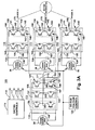
- FIG. 3A illustrates a simplified embodiment of the 7-level, wye-connected H-bridge converter topology.
- the converter includes a plurality of H-bridges output phases 110, 111, 112.
- Each H-bridge output phase includes an H-bridge 150 with semiconductor switches (a representative semiconductor switch 140 with internal diode 145 and gating input 147).
- Each H-bridge includes an output leg 160 and a connecting leg 165.
- Each output leg 160 and connecting leg 165 includes an upper semiconductor switch 141 and a lower semiconductor switch 142 of the leg.
- a midpoint is located between the upper semiconductor switch and the lower semiconductor switch in each leg.
- the midpoints 185 of the output legs 160 provide phase outputs 170, 175, 180 for H-bridge output phases A 110, B 111 and C 112 of the converter 100.
- the midpoints 195 of the connecting legs 165 provide connecting outputs 186, 187, 188 to corresponding phase legs of a mid-bridge 113.
- Each H-bridge output phase 110, 111, 112 also includes a power source/sink 20 with a dc power shaping circuit, represented by capacitor 30.
- the power source/sink/ 20 and dc power shaping circuit, represented by capacitor 30, establish a voltage on the dc-bus 135 that supplies the semiconductor switches 140 of the H-bridges 150.
- the converter further includes the semiconductor mid-bridge phase 113.
- the mid-bridge phase 113 includes a power source/sink 20 with a dc power shaping circuit, represented by capacitor 30.
- the power source/sink/ 20 and dc power shaping circuit, represented by capacitor 30, establish voltage at dc-bus 135 for the semiconductor switches 140 of the mid-bridge 155.
- the mid-bridge phase 113 includes the three-phase semiconductor mid-bridge 155 with semiconductor switches (a representative semiconductor switch 140 with internal diode 145 and gating input 147).
- the three-phase semiconductor mid-bridge 155 includes three legs, leg 1 156, leg 2 157 and leg 3 158. Each of the three phase legs includes an upper semiconductor switch 141 and a lower semiconductor switch 142.
- the midpoint of each leg provides an output.
- the midpoint 201 of phase A leg 156 may be tied to the connecting output 186 of H-bridge output phase A 110.
- the midpoint 202 of phase B leg 157 may be tied to the connecting output 187 of H-bridge output phase B 111.
- the midpoint 203 of phase C leg 158 may be tied to the connecting output 188 of H-bridge output phase C 112.
- Insulated-gate bipolar transistors (IGBTs) 140 with built-in diodes 145 may form each leg of the H-bridges 150 and the mid-bridge 155, for example, but other power semiconductor switches such as integrated-gate commutated thyristors (IGCTs) or metal-oxide semiconductor field-effect transistors (MOSFETs) could be used instead.
- IGCTs integrated-gate commutated thyristors
- MOSFETs metal-oxide semiconductor field-effect transistors
- a gating control 115 may provide gating signals 116, 117, 118 119 to the semiconductor devices 140 for the H-bridge output phases 110, 111, 112, and mid-bridge phase 113, respectively.
- the gating controls 115 may provide the gating signals 116, 117, 118 119 according to predetermined switching patterns.
- Gating controls may provide for synchronous switching of the semiconductor switches 140.
- the gating controls 115 may also provide synchronous switching patterns that include notches of designated width and designated position with respect to the zero-current crossing for converter line current.
- the gating controls for the bridges may be performed by a microprocessor, an integrated circuit, a field programmable gate array (FPGA) or other electronic circuits known in the art.
- FPGA field programmable gate array
- a dc-bus voltage control 138 may provide voltage control signals to the power source/sink 20 for individually setting the dc voltage on the dc-bus 135 for the H-bridge output phases 110, 111, 112 and the mid-bridge phase 113.
- the dc-bus voltage control 138 may provide alternate settings for voltage on the dc-bus 135 by contactor selection of alternate tap settings (not shown) on a power source/sink. Such alternate voltage settings may be provided by selection of multiple taps on isolated secondary winding of power supply transformers (not shown) or other methods known to the art.
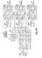
- FIG. 3B A more detailed arrangement of the 7-level wye-connected H-bridge converter topology is illustrated in FIG. 3B .
- Each bridge may be supplied by an isolated phase winding 210, 215, 220 for a phase from a transformer 205.
- the output of the transformer is rectified in a rectifier bank 247 and output to the dc-bus 135 for the bridge.
- the topology includes bypass contactors in circuit locations that permit it to be reconfigured to a 5-level wye-connected H-bridge in the event of a failure of any bridge.
- a H-bridge output phase bypass contactor may be provided around the semiconductor H-bridge between the connecting output of the connecting leg and the phase output of the output leg.
- a mid-bridge bypass contactor may be provided.
- the mid-bridge bypass contactor includes a plurality of contacts that isolate a failed mid-bridge by creating a wye-connection among the connecting outputs for the three functioning H-bridges.
- contacts for the mid-bridge contactor may also function to connect the mid-bridge as a third H-bridge in place of a failed and bypassed H-bridge. In this case, the midpoint output from one phase leg of the mid-bridge is connected to the line output from the failed and bypassed H-bridge and a second midpoint output is wye-connected to the connecting output from the remaining two functioning H-bridges.
- the mid-bridge contactor 280 includes contacts 281, 282 and 283. When contacts 281, 282 and 283 are all open, the connecting outputs 186, 187, 188 of H-bridge phase A 110, H-bridge phase B 111 and H-bridge phase C 112 respectively are connected to the midpoints 201, 202, 203 of the associated phase leg 156, 157, 158 of the mid-bridge 113.
- contact 281 ties the connecting output 186 of H-bridge output phase A 111 and the midpoint 201 for phase A leg 156 of the mid-bridge 113 with the connecting output 188 of H-bridge phase C 112 and the midpoint 203 of phase C leg 158 of mid-bridge 113.
- contact 282 ties the connecting output 186 of H-bridge output phase A 110 and the midpoint 201 for phase A leg 1 156 of the mid-bridge 113 with the connecting output 187 of H-bridge output phase B 112 and the midpoint 202 of phase B leg of mid-bridge 113.
- contact 283 ties the connecting output 187 of H-bridge phase B 111 and the midpoint 202 for phase B leg 157 of the mid-bridge 113 with the connecting output 188 of H-bridge phase C 112 and the midpoint 203 for phase C leg 158 of mid-bridge 113.
- Closing mid-bridge bypass contact 281 and H-bridge bypass contact 197 bypasses the H-bridge output phase B 111 and makes mid-bridge 155 act as an H-bridge in a three-phase, wye-connected H-bridge configuration.
- Closing mid-bridge bypass contact 282 and H-bridge bypass contact 198 bypasses the H-bridge output phase C 113, making mid-bridge 155 act as an H-bridge in a three-phase, wye-connected H-bridge configuration.
- Closing mid-bridge bypass contact 283 and H-bridge bypass contact 196 bypasses the H-bridge output phase A 110, making mid-bridge 155 to act as an H-bridge in a three-phase, wye-connected H-bridge configuration.
- FIG. 4 illustrates an embodiment of the inventive 7-level wye-connected H-converter bridge reconfigured to a 5-level wye-connected H-bridge.
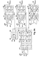
- FIG. 5A illustrates an embodiment of an inventive 7-level wye-connected H-bridge converter reconfigured by bypassing a failed H-bridge output phase 112.
- FIG. 5B illustrates an embodiment of an inventive 7-level wye-connected H-bridge converter reconfigured by bypassing a failed mid-bridge.
- a control function 260 controls the H-bridge output phase bypass contacts 196, 197, 198 and the mid-bridge bypass contactor 280.
- the control function 260 performs as follows employing solid-state contactors, mechanical contactors or other methods known in the art.
- the bypass contact for a H-bridge output phase is in a normal open state when the associated H-bridge output phase is functioning normally and is in a closed state when the H-bridge output phase is failed.
- the plurality of mid-bridge bypass contacts for the mid-bridge bypass contactor are in an open state when the mid-bridge is functioning normally and the plurality of H-bridge output phases are functioning normally.
- the plurality of mid-bridge bypass contactors are in a closed state when the mid-bridge is failed and the plurality of H-bridge output phases are functioning normally.
- One mid-bridge bypass contactor is associated with a failure of one H-bridge output phase and is in a closed state to connect the connecting output of one functioning H-bridge with the connecting output of another functioning H-bridge when an associated H-bridge fails.
- the converter is coupled with a 15 MW, 10,000 RPM, 333 Hz, with about a 6 KV line voltage.
- the invention should be considered applicable to other high speed electric motors (HSEMs) and ac-motors, in general.
- the converter may also be considered for driving an 11 MW, 14,000 RPM, 467 Hz, with a line voltage of about 4 KV to about 6 KV, and a 6 MW, 17,000 RPM, 567 Hz, with a line voltage of about 4 KV to about 6 KV.
- a power source/sink 20 is illustrated. It should be understood that the converter 100 is adaptable to absorb regenerative power from the motor load, the power being delivered through the converter to the power sink of power source/sink 20. Further, in place of the motor load, a generating source such as a generator may be provided. The converter 100 and converter control 115 are adaptable to transferring the generated ac power to the power source/sink 20.
- Synchronous switching schemes with fixed pulse patterns and without notches may be applied to the semiconductor devices of the bridges for the converter. Notches may also be inserted around fundamental frequency pulses of the fixed pulse patterns to improve total harmonic distortion (THD) performance on the output line current of the converter. Higher effective switching rates due to the insertion of notches may incur higher switching losses on the semiconductor switches, putting the semiconductor switch closer to thermal margins and potentially impacting reliability of operation.
- THD total harmonic distortion
- positioning of the notches of the fixed pulse pattern for an individual bridge to be in close proximity to zero-current crossing of the output line current for the same individual bridge may limit the switching loss and at the same time achieve improved THD of the line current.
- a zero-current notch switching pattern with two notches ZCnotch2
- ZCnotch2 switching pattern may be applied selectively to individual bridges of the converter. Such selective application may be based on applying the ZCnotch2 switching pulse pattern to individual bridges, which have sufficient thermal margin in semiconductor operation to tolerate somewhat higher switching losses in order to improve THD.
- the semiconductor switches of the mid-bridge may be more thermally limiting than the semiconductor switches of the H-bridges.
- the ZCnotch2 switching pulse pattern may be applied to the semiconductor switches of the H-bridges, but synchronous switching pulse pattern without notches applied to the semiconductor switches of the mid-bridge.
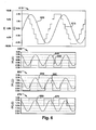
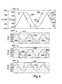
- FIG. 6 illustrates graphs of optimum pulse positions for minimum voltage harmonic distortion in the output where the switching frequency equals the fundamental frequency (no notches), when the converter supplies a 6.2 KV line-to-line output voltage, a 1746 ARMS output current, and 15.0 MW output power. Balanced dc-bus voltages are applied to every bridge.
- Graph 610 illustrates the phase relationship between 7-level line-to-line output voltage 615 (voltage phase A to phase B) for the converter and line current 620 for phase A.
- Graph 630 illustrates the phase relationship (PF of 0.812) between line current 640 for phase A and a switching pattern 645 for H-bridge output leg phase A.
- Graph 650 illustrates the phase relationship (PF of 0.962) between line current for phase A and a switching pattern for H-bridge connecting leg phase A. The phase relationships are applicable for the line current of the other H-bridge phases and the related H-bridge phase A output leg and connecting leg.
- Graph 670 illustrates the phase relationship (PF of 0.519) between line current 675 for phase A and the switching pattern for the mid-bridge phase A leg. The switching pattern for the semiconductor switches of each phase are synchronous with the switched leg voltage for the respective phase. With four-bridges operating, the line current carried a total harmonic distortion of 2.00%. Other parameters for the operation in this configuration are provided in TABLE I.
- the converter may also operate with reduced dc bus voltage provided to the mid-bridge. Reduced dc bus voltage will reduce switching loss on the mid-bridge, allowing the mid-bridge to deliver higher current at a lower voltage.
- FIG. 7 illustrates optimum pulse positions for minimum voltage harmonic distortion in the output where the switching frequency equals the fundamental frequency (no notches), when the converter supplies a 6.2 KV line-to-line output voltage, a 1746 ARMS output current, and 15.0 MW output power.
- Balanced dc-bus voltages are applied to each H-bridge, but dc-bus voltage to the mid-bridge is reduced.
- Graph 710 illustrates the relationship between stepped line-to-line output voltage 710 (voltage phase A to phase B) for the converter and line current 715 for phase A.
- Graph 730 illustrates the phase relationship (PF of 0.812) between line current 740 for phase A and a switching pattern for 745 for H-bridge output leg phase A.
- Graph 750 illustrates the phase relationship (PF of 0.800) between line current 755 for phase A and switching pattern 760 for H-bridge connecting leg phase A. The phase relationships are applicable for the line current of phase A and phase B and the related H-bridge phase output leg and connecting leg.
- Graph 770 illustrates the phase relationship (PF of 0.509) between line current 775 for phase A and the switching pattern 780 for the mid-bridge. The switching pattern for the semiconductor switches of each phase are synchronous with the switched leg voltage for the respective phase. Reduced dc-bus voltage applied to the mid-bridge causes a smaller magnitude output voltage from the mid-bridge phase leg compared to the H-bridge phase leg voltage .
- a zero-current switching waveform is provided for the 7-level wye-connected H-bridge to power a large high-speed electric motor (HSEM).
- the switching waveform includes two notches per cycle on the switching waveform provided to each of the semiconductor switches.
- the switching waveform is referred to as a ZC (Zero Current) notch2 waveform.
- IGCT gate drive power may be reduced due to the low gate charge for switching events at low current, thereby improving the reliability of IGCT gate drive circuit.
- the ZCnotch2 switching waveform makes the effective switching frequency equal to two times the fundamental frequency.
- the Zcnotch2 switching waveform may further be optimized to equalize power semiconductor losses between upper and lower devices in each leg of the H-bridge, thereby providing margin to operating limits. Further, the ZCnotch2 switching waveform utilized in H-bridge, retains the property that the output voltage at the output of every H-bridge is symmetrical, eliminating even harmonics.
- the switching signals for the bridge may be controlled by a microprocessor, an integrated circuit, a field programmable gate array (FPGA) or other electronic circuits known in the art.
- a microprocessor an integrated circuit
- FPGA field programmable gate array
- FIG. 8 illustrates graphs of optimum pulse and notch positions for minimum current harmonic distortion in the output where a synchronous switching pulse pattern with no notches is applied to the semiconductor switches of the mid-bridge and a zero-current switching pattern with two notches per cycle placed in proximity to zero-current crossing is applied to the semiconductor switches of the H-bridge output phases.
- the gating signals are applied from the gating controls 115 ( FIG. 3A ) when the converter supplies a 6.2 KV line-to-line output voltage, a 1746 ARMS output current, and 15.0 MW output power. Balanced dc-bus voltages are applied to every bridge.
- Graph 810 illustrates the phase relationship between 7-level line-to-line output voltage 815 (voltage phase A to phase B) for the converter and line current 820 for phase A.
- ZCnotch2 notches applied in the switching pulse pattern to the semiconductor switches for H-bridges, appear as multiple notches 825 in the line-to-line output voltage 815.
- Graph 830 illustrates the phase relationship (PF of 0.963) between line current 840 for phase A and the switching pattern 845 for H-bridge leg 1.
- ZCnotch2 notches applied in the switching pattern 845 to the semiconductor switches for H-bridge output leg phase A appear as multiple notches 835 in close proximity to the edge of the switching pulses.
- Graph 850 illustrates the phase relationship (PF of 0.796) between line current 855 for phase A and the switching pattern 860 for H-bridge connecting leg phase A.
- ZCnotch2 notches applied in the switching pattern 860 to the semiconductor switches for H-bridge output leg phase A appear as two notches 865 per cycle, offset from the edge of the switching pulses. Similar phase relationships are applicable for line current and H-bridge voltage for leg 1 and leg 2 in H-bridge output phases B and C.
- Graph 870 illustrates the phase relationship (PF of 0.519) between line current 875 for phase A and the synchronous switching pattern 880 for the mid-bridge phase legs. No notches are present in the voltage 880 because synchronous switching without notches is applied to the semiconductor switches for the phase legs of the mid-bridge.
- the switching pattern for the semiconductor switches of each phase are synchronous with the switched leg voltage (not shown) for the respective phase.
- the line current carried a total harmonic distortion of 0.87%.
- Other parameters for the operation in this configuration are provided in TABLE III.
- the limiting peak junction temperature for the semiconductors occurred in the mid-bridge, where the calculated temperature of 114.9 degree C did not exceed the thermal limit of 115 degree C.
Landscapes
- Engineering & Computer Science (AREA)
- Power Engineering (AREA)
- Inverter Devices (AREA)
- Rectifiers (AREA)
Applications Claiming Priority (1)
| Application Number | Priority Date | Filing Date | Title |
|---|---|---|---|
| US11/821,257 US7643319B2 (en) | 2007-06-22 | 2007-06-22 | 7-level wye-connected H-bridge converter topology for powering a high-speed electric motor |
Publications (2)
| Publication Number | Publication Date |
|---|---|
| EP2006993A2 true EP2006993A2 (fr) | 2008-12-24 |
| EP2006993A3 EP2006993A3 (fr) | 2016-10-19 |
Family
ID=39767107
Family Applications (1)
| Application Number | Title | Priority Date | Filing Date |
|---|---|---|---|
| EP08158374.2A Withdrawn EP2006993A3 (fr) | 2007-06-22 | 2008-06-17 | Convertisseur pont (onduleur) en connexion étoile à 7 niveaux pour alimenter un moteur électrique à haute vitesse |
Country Status (2)
| Country | Link |
|---|---|
| US (1) | US7643319B2 (fr) |
| EP (1) | EP2006993A3 (fr) |
Cited By (4)
| Publication number | Priority date | Publication date | Assignee | Title |
|---|---|---|---|---|
| EP2744096A1 (fr) * | 2012-12-12 | 2014-06-18 | Magna Steyr Fahrzeugtechnik AG & Co KG | Dispositif d'alimentation en énergie |
| CN104428988A (zh) * | 2012-04-06 | 2015-03-18 | 恩宝微系统有限公司 | 具有多个直流电源的双向换能器 |
| EP3163732A1 (fr) | 2015-10-28 | 2017-05-03 | GE Energy Power Conversion Technology Ltd | Système de conversion de puissance bidirectionnel pour charge électrique monophasée et procédé de conversion de puissance correspondant |
| CN104081647B (zh) * | 2012-01-25 | 2019-08-13 | 阳光电源股份有限公司 | 带有独立直流电源的堆叠电压源逆变器 |
Families Citing this family (15)
| Publication number | Priority date | Publication date | Assignee | Title |
|---|---|---|---|---|
| US8050063B2 (en) * | 2007-05-31 | 2011-11-01 | General Electric Company | Systems and methods for controlling a converter for powering a load |
| US7994750B2 (en) * | 2008-04-29 | 2011-08-09 | General Electric Company | Systems and methods for controlling a converter for powering a load |
| US8374009B2 (en) * | 2010-03-25 | 2013-02-12 | Hamilton Sundstrand Corporation | Multi-level parallel phase converter |
| DE102010013862A1 (de) * | 2010-04-01 | 2011-10-06 | Gottfried Wilhelm Leibniz Universität Hannover | Transformatorloser Direktumrichter |
| CN102005957B (zh) * | 2010-11-04 | 2013-11-06 | 燕山大学 | 单电源级联多电平变流器 |
| US8842454B2 (en) * | 2010-11-29 | 2014-09-23 | Solarbridge Technologies, Inc. | Inverter array with localized inverter control |
| CN103782471B (zh) | 2011-07-11 | 2017-08-22 | 赛恩沃茨公司 | 用于太阳能光伏能量收集和转换的系统及方法 |
| US9263971B2 (en) | 2011-12-16 | 2016-02-16 | Empower Micro Systems Inc. | Distributed voltage source inverters |
| US8897014B2 (en) | 2012-09-04 | 2014-11-25 | General Electric Company | Mechanical layout for half-bridge power module that is optimized for low inductance |
| TWI465030B (zh) * | 2012-10-30 | 2014-12-11 | Ind Tech Res Inst | 多驅動裝置及其驅動電路 |
| EP2728713A1 (fr) * | 2012-10-31 | 2014-05-07 | Openhydro IP Limited | Machine électrique |
| KR102038119B1 (ko) * | 2012-11-09 | 2019-10-29 | 삼성전자주식회사 | 전자 장치, 전원 공급 장치 및 전원 공급 방법 |
| US9455651B2 (en) | 2014-12-16 | 2016-09-27 | Caterpillar Inc. | Motor driver having integrated braking chopper |
| KR102485705B1 (ko) * | 2016-02-18 | 2023-01-05 | 엘에스일렉트릭(주) | 멀티 레벨 인버터의 3상 평형 전압 제어 방법 |
| WO2019094586A1 (fr) * | 2017-11-09 | 2019-05-16 | North Carolina State University | Circuit pour fournir une excitation de forme d'onde variable |
Family Cites Families (5)
| Publication number | Priority date | Publication date | Assignee | Title |
|---|---|---|---|---|
| DE19615855A1 (de) * | 1996-04-20 | 1997-10-23 | Asea Brown Boveri | Leistungselektronische Schaltungsanordnung |
| GB2330254B (en) * | 1997-10-09 | 2000-10-18 | Toshiba Kk | Multiple inverter system |
| US5986909A (en) * | 1998-05-21 | 1999-11-16 | Robicon Corporation | Multiphase power supply with plural series connected cells and failed cell bypass |
| JP3502566B2 (ja) * | 1999-05-18 | 2004-03-02 | 三菱電機株式会社 | 電力変換装置 |
| DE10143279B4 (de) * | 2001-09-04 | 2009-05-28 | Semikron Elektronik Gmbh & Co. Kg | Frequenzumrichter |
-
2007
- 2007-06-22 US US11/821,257 patent/US7643319B2/en not_active Expired - Fee Related
-
2008
- 2008-06-17 EP EP08158374.2A patent/EP2006993A3/fr not_active Withdrawn
Cited By (4)
| Publication number | Priority date | Publication date | Assignee | Title |
|---|---|---|---|---|
| CN104081647B (zh) * | 2012-01-25 | 2019-08-13 | 阳光电源股份有限公司 | 带有独立直流电源的堆叠电压源逆变器 |
| CN104428988A (zh) * | 2012-04-06 | 2015-03-18 | 恩宝微系统有限公司 | 具有多个直流电源的双向换能器 |
| EP2744096A1 (fr) * | 2012-12-12 | 2014-06-18 | Magna Steyr Fahrzeugtechnik AG & Co KG | Dispositif d'alimentation en énergie |
| EP3163732A1 (fr) | 2015-10-28 | 2017-05-03 | GE Energy Power Conversion Technology Ltd | Système de conversion de puissance bidirectionnel pour charge électrique monophasée et procédé de conversion de puissance correspondant |
Also Published As
| Publication number | Publication date |
|---|---|
| US7643319B2 (en) | 2010-01-05 |
| EP2006993A3 (fr) | 2016-10-19 |
| US20080316778A1 (en) | 2008-12-25 |
Similar Documents
| Publication | Publication Date | Title |
|---|---|---|
| US7643319B2 (en) | 7-level wye-connected H-bridge converter topology for powering a high-speed electric motor | |
| US8050063B2 (en) | Systems and methods for controlling a converter for powering a load | |
| US12237779B2 (en) | Efficient switching for converter circuit | |
| US7643318B2 (en) | Dual voltage wye-connected H-bridge converter topology for powering a high-speed electric motor | |
| US7847507B2 (en) | Zero-current notch waveform for control of a three-phase, wye-connected H-bridge converter for powering a high-speed electric motor | |
| Li et al. | A hybrid modular multilevel converter with novel three-level cells for DC fault blocking capability | |
| US8462524B2 (en) | 3-level pulse width modulation inverter with snubber circuit | |
| US10177684B2 (en) | Converter for an AC system | |
| US20200195130A1 (en) | Methods and systems for controlling current source rectifiers | |
| JP5022910B2 (ja) | マトリックス変換器 | |
| Ugur et al. | Design of a GaN based integrated modular motor drive | |
| Nagel et al. | A 24 MVA inverter using IGCT series connection for medium voltage applications | |
| Mohamadian et al. | A novel thyristor-based CSI topology with multilevel current waveform for improved drive performance | |
| WO2019007526A1 (fr) | Convertisseur de puissance hybride | |
| Farnesi et al. | A new fault tolerant NPC converter system for high power induction motor drives | |
| Bakas et al. | Hybrid converter with alternate common arm and director thyristors for high-power capability | |
| Bruckner et al. | Investigation of a high-power three-level quasi-resonant DC-link voltage-source inverter | |
| EP3476031A1 (fr) | Protection de semi-conducteurs dans des convertisseurs de puissance | |
| Liu et al. | Active Current Transferring Modular Multilevel Converter With DC Fault Blocking Capacity | |
| CN108604877A (zh) | 链式链路转换器的子模块 | |
| Bruckner et al. | New medium-voltage inverter design with very high power density | |
| Etxeberria-Otadui et al. | Analysis of IGCT current clamp design for single phase H-bridge converters | |
| Bhattacharya | Comparative evaluation of IGCT and GTO thyristor for series connection in high power voltage source inverter based FACTS applications | |
| Magesh et al. | IMPLEMENTATION OF SINGLE PHASE NEUTRAL POINT CLAMPED GRID CONNECTED INVERTER WITH OPEN SWITCH FAULT DETECTION AND CORRECTION | |
| Shang | Space Vector Modulation Methods for Common-Mode Voltage Reduction in Current-Source Drives |
Legal Events
| Date | Code | Title | Description |
|---|---|---|---|
| PUAI | Public reference made under article 153(3) epc to a published international application that has entered the european phase |
Free format text: ORIGINAL CODE: 0009012 |
|
| AK | Designated contracting states |
Kind code of ref document: A2 Designated state(s): AT BE BG CH CY CZ DE DK EE ES FI FR GB GR HR HU IE IS IT LI LT LU LV MC MT NL NO PL PT RO SE SI SK TR |
|
| AX | Request for extension of the european patent |
Extension state: AL BA MK RS |
|
| PUAL | Search report despatched |
Free format text: ORIGINAL CODE: 0009013 |
|
| RIC1 | Information provided on ipc code assigned before grant |
Ipc: H02M 7/49 20070101ALI20160816BHEP Ipc: H02M 7/5387 20070101AFI20160816BHEP Ipc: H02M 1/32 20070101ALI20160816BHEP |
|
| AK | Designated contracting states |
Kind code of ref document: A3 Designated state(s): AT BE BG CH CY CZ DE DK EE ES FI FR GB GR HR HU IE IS IT LI LT LU LV MC MT NL NO PL PT RO SE SI SK TR |
|
| AX | Request for extension of the european patent |
Extension state: AL BA MK RS |
|
| AKY | No designation fees paid | ||
| AXX | Extension fees paid |
Extension state: BA Extension state: AL Extension state: RS Extension state: MK |
|
| REG | Reference to a national code |
Ref country code: DE Ref legal event code: R108 |
|
| STAA | Information on the status of an ep patent application or granted ep patent |
Free format text: STATUS: THE APPLICATION IS DEEMED TO BE WITHDRAWN |
|
| 18D | Application deemed to be withdrawn |
Effective date: 20170420 |