EP2007085A1 - Netzvorrichtung und netzsystem, verfahren zur ausgabe von ipv6-adressen und verfahren zur verwaltung einer netzvorrichtung - Google Patents
Netzvorrichtung und netzsystem, verfahren zur ausgabe von ipv6-adressen und verfahren zur verwaltung einer netzvorrichtung Download PDFInfo
- Publication number
- EP2007085A1 EP2007085A1 EP07740419A EP07740419A EP2007085A1 EP 2007085 A1 EP2007085 A1 EP 2007085A1 EP 07740419 A EP07740419 A EP 07740419A EP 07740419 A EP07740419 A EP 07740419A EP 2007085 A1 EP2007085 A1 EP 2007085A1
- Authority
- EP
- European Patent Office
- Prior art keywords
- network
- ipv6 address
- network device
- interface
- number indicating
- Prior art date
- Legal status (The legal status is an assumption and is not a legal conclusion. Google has not performed a legal analysis and makes no representation as to the accuracy of the status listed.)
- Withdrawn
Links
Images


Classifications
-
- H—ELECTRICITY
- H04—ELECTRIC COMMUNICATION TECHNIQUE
- H04L—TRANSMISSION OF DIGITAL INFORMATION, e.g. TELEGRAPHIC COMMUNICATION
- H04L61/00—Network arrangements, protocols or services for addressing or naming
- H04L61/50—Address allocation
- H04L61/5092—Address allocation by self-assignment, e.g. picking addresses at random and testing if they are already in use
-
- H—ELECTRICITY
- H04—ELECTRIC COMMUNICATION TECHNIQUE
- H04L—TRANSMISSION OF DIGITAL INFORMATION, e.g. TELEGRAPHIC COMMUNICATION
- H04L61/00—Network arrangements, protocols or services for addressing or naming
- H04L61/35—Network arrangements, protocols or services for addressing or naming involving non-standard use of addresses for implementing network functionalities, e.g. coding subscription information within the address or functional addressing, i.e. assigning an address to a function
-
- H—ELECTRICITY
- H04—ELECTRIC COMMUNICATION TECHNIQUE
- H04L—TRANSMISSION OF DIGITAL INFORMATION, e.g. TELEGRAPHIC COMMUNICATION
- H04L2101/00—Indexing scheme associated with group H04L61/00
- H04L2101/60—Types of network addresses
- H04L2101/604—Address structures or formats
-
- H—ELECTRICITY
- H04—ELECTRIC COMMUNICATION TECHNIQUE
- H04L—TRANSMISSION OF DIGITAL INFORMATION, e.g. TELEGRAPHIC COMMUNICATION
- H04L2101/00—Indexing scheme associated with group H04L61/00
- H04L2101/60—Types of network addresses
- H04L2101/618—Details of network addresses
- H04L2101/659—Internet protocol version 6 [IPv6] addresses
Definitions
- the present invention relates to a network device and a network system performing address management on a network on the basis of IPv6 (Internet Protocol version 6) which is a communication protocol for general use on the Internet, and connected to the network using an IPv6 address and to an IPv6 address assigning method and a network device managing method.
- IPv6 Internet Protocol version 6
- an IPv6 address which is assigned to a network device connected to the network is 128 bits long.
- the first-half 64 bits are allocated to a network prefix included in RA (Router Advertisement) from a router.
- the second-half 64 bits are allocated to an EUI-64 format interface ID as a 64-bit identifier decided by the IEEE.
- an MAC address is encapsulated.
- the former 24 bits are allocated to a number indicating a manufacturer administrated by the IEEE, the next 16 bits are allocated to "FFFE", and the latter 24 bits are allocated to an expanded identification number managed by a manufacturer.
- IPv6 address allocated in this manner ensures uniqueness in that the MAC address encapsulated in the interface ID is not overlapped and a unique number.
- control device When a network device (control device) to which the IPv6 address is assigned controls another network device (controlled device), identification information of the controlled device managed by a database server on a network is referred to control access to the controlled device on the basis of the identification information of the controlled device.
- filtering or high-level services in an IP packet transfer is functionally limited in accordance with a value of an interface ID contained in an IPv6 address of a device connected to a network. Accordingly, security is improved. Moreover, information indicating communication contents or a device attribute is contained in the interface ID, thereby performing communication control corresponding to the relevant attribute.
- Patent Document 1 JP-A-2004-289782
- the MAC address is decided by a network device maker at the time of device manufacture with a rule by which it is difficult to recognize network devices. For that reason, when access to the network devices is controlled by the IPv6 addresses on the basis of the identification information of the controlled device, a database server storing the identification information of all the network devices connected to the network has to be used. Moreover, there occurs a problem in that flexible IPv6 addresses cannot be assigned to the network devices.
- the invention is devised in view of the above-described circumstances and an object of the invention is to provide a network device and a network system capable of explicitly identifying network devices without providing a database server having an IPv6 address, and provide an IPv6 address assigning method and a network device managing method.
- Another object of the invention is to provide a network device and a network system capable of constructing a high secure network and provide an IPv6 address assigning method and a network device managing method, since the network device as an access target can be managed in accordance with a management system of the network device such as a device type, a function, and a function.
- the prevention includes configurations described below.
- a network device which performs address management on a network on the basis of IPv6 and is connected to the network using an IPv6 address.
- the network device has the IPv6 address assigned so as to contain a number indicating a management system type of a device in a part of an interface ID of the IPv6 address.
- each device on the network can explicitly identifies a target network device on the basis of the management system of the device using the number indicating the management system type of the interface ID in the IPv6 address.
- device type information is used in a case where the management system type is a device type and location information is used in a case where the management system type is a location. Accordingly, a communication protocol in an application layer can be simplified, since it is not necessary to transmit and receive information with the database server in order to identify the network device.
- the network device in which the IPv6 address further contains a number indicating device type information on the device in a part of the interface ID.
- the network device in which the IPv6 address further contains a number indicating function information on the device in a part of the interface ID.
- the IPv6 address further contains a number indicating function information on the device in a part of the interface ID.
- the network device in which the IPv6 address further contains a number indicating location information on the device in a part of the interface ID
- the IPv6 address further contains a number indicating location information on the device in a part of the interface ID
- the network device in which the IPv6 address further contains a number indicating function information on the device in a part of the interface ID.
- the IPv6 address further contains a number indicating function information on the device in a part of the interface ID.
- the network device which has as the IPv6 address a plurality of IPv6 addresses having the interface IDs different from each other.
- the plurality of IPv6 addresses can individually used in accordance with a control-side circumstance. Accordingly, it is possible to perform access, control, and the like with reference to the IPv6 address which is the most optimum management system in the network devices.
- the network device which has as the IPv6 address a first IPv6 address which contains a number indicating device type information on the device in a part of the interface ID and a second IPv6 address which contains a number indicating location information on the device in a part of the interface ID.
- the IPv6 address using the device type information and the IPv6 address using the location information can individually used in accordance with the control-side circumstance. Accordingly, it is possible to perform access, control, and the like with reference to the IPv6 address which is the most optimum management system in the network devices.
- a network system which includes the network device according to (2) and performs at least one of access and control by permitting inter-device communication using the number indicating the device type information in the interface ID.
- a communication protocol such as a Web access protocol by using the IPv6 address containing the number indicating the device type information when access, control, and the like are performed on the target network device.
- a network system which includes the network device according to (3) and performs at least one of access and control by permitting inter-device communication using the number indicating the device type information and the number indicating the function information in the interface ID.
- a network system which includes the network device according to (3) and which controls communication using the number indicating the device type information and the number indicating the function information in the interface ID, so that VPN is constructed by IPsec.
- a network system which includes the network device according to (4) and performs at least one of access and control by permitting inter-device communication using the number indicating the location information in the interface ID.
- a communication protocol such as the Web access protocol by using the IPv6 address containing the number indicating the location information when access, control, and the like are performed on the target network device.
- a network system which includes the network device according to (5) and performs at least one of access and control by permitting inter-device communication using the number indicating the location information and the number indicating the function information in the interface ID.
- a network system which includes the network device according to (5) and which controls communication using the number indicating the location information and the number indicating the function information in the interface ID, so that VPN is constructed by IPsec.
- the method includes assigning the IPv6 address so as to contain a number indicating a management system type of a device in a part of an interface ID of the IPv6 address set in association with every target device.
- the device type information is used in a case where the management system type is the device type and location information is used in a case where the management system type is the location. Accordingly, a communication protocol in an application layer can be simplified, since it is not necessary to transmit and receive information with the database server in order to identify the network device.
- the IPv6 address assigning method in which the IPv6 address further includes a number indicating device type information on the device for specifying the device in a part of the interface ID.
- the IPv6 address assigning method in which the IPv6 address further contains a number indicating function information on the device belonging to the device in a part of the interface ID.
- the IPv6 address assigning method in which the IPv6 address further contains a number indicating location information on the device for specifying the device in a part of the interface ID.
- the IPv6 address assigning method according to (14) in which as the IPv6 address a plurality of IPv6 addresses having the interface IDs different from each other are assigned to one network device.
- the plurality of IPv6 addresses can individually used in accordance with a control-side circumstance. Accordingly, it is possible to perform access, control, and the like with reference to the IPv6 address which is the most optimum management system in the network devices.
- the IPv6 address assigning method in which as the IPv6 address a first IPv6 address which contains a number indicating device type information on the device in a part of the interface ID and a second IPv6 address which contains a number indicating location information on the device in a part of the interface ID are assigned to one network device.
- the IPv6 address using the device type information and the IPv6 address using the location information can individually used in accordance with the control-side circumstance. Accordingly, it is possible to perform access, control, and the like with reference to the IPv6 address which is the most optimum management system in the network devices.
- a network device managing method including communicating with a network device having the IPv6 address according to (2) using the number indicating the device type information in the interface ID to perform at least one of access and control.
- a network device managing method including communicating with a network device having the IPv6 address according to (3) using the number indicating the device type information and the number indicating the function information in the interface ID to perform at least one of access and control.
- a network device managing method including controlling communication with a network device having the IPv6 address according to (3) using the number indicating the device type information and the number indicating the function information in the interface ID, so that VPN is constructed by IPsec.
- a network device managing method including communicating with a network device having the IPv6 address according to (4) using the number indicating the location information in the interface ID to perform at least one of access and control.
- a network device managing method including communicating with a network device having the IPv6 address according to (5) using the number indicating the location information and the number indicating the function information in the interface ID to perform at least one of access and control.
- a network device managing method including controlling communication with a network device having the IPv6 address according to (5) using the number indicating the location information and the number indicating the function information in the interface ID, so that VPN is constructed by IPsec.
- a network device capable of explicitly identifying the network devices without providing a database server having an IPv6 address.
- the network device the network system, the IPv6 address assigning method, and the network device managing method capable of constructing high secure network, since the network device as an access target can be managed in accordance with a management system of the network device such as a device type, a function, and a location.
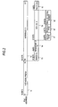
- Fig. 1 is a diagram illustrating a configuration example of an IPv6 network system according to embodiments of the invention.
- the IPv6 network system has a configuration in which a maintenance terminal 1, a control terminal 2, and display terminals 3 and 4 are connected to a network 6 such as the Internet capable of employing IPv6 through a router 5, and cameras 8 and 9 are connected to the network 6 through a router 7.
- the maintenance terminal 1, the control terminal 2, the display terminals 3 and 4, the routers 5 and 7, and the cameras 8 and 9 are network devices which are connected to the IPv6 network and to which IPv6 addresses are assigned.
- the network devices are configured to manage addresses on the IPv6 network using IPv6 addresses and carry out communication, access control, and the like between the network devices.
- Fig. 2 is a diagram illustrating a structure of the IPv6 addresses assigned to the network devices according to a first embodiment.
- the IPv6 addresses has 128 bits long, and is composed of a first-half 64-bit network prefix 11 and a second-half 64-bit interface ID 12.
- the interface ID 12 has a maker ID 13, a management ID 14, a device ID 15, and a function ID 16.
- the management ID 14 corresponds to an example of a number indicating a management system type
- the device ID 15 corresponds to an example of a number indicating device type information
- the function ID 16 corresponds to an example of a number indicating function information.
- IPv6 network system access to the camera 8 is permitted to perform various types of control by transmitting an IPv6 packet containing control information from the control device 2 to the camera 8, when the camera 8 is controlled by the control terminal 2, for example.
- the IPv6 packet includes a source IPv6 address indicating a source network device and a destination IPv6 address indicating a destination network device.
- the former 24 bits of each MAC address held by network device makers are assigned to the maker ID 13 of the 64-bit interface ID 12.
- 4 bits indicating the management system type of a device are assigned to the management ID 14.
- information indicating the management by a device type is configured so as to be contained as the management system type 6 bits indicating a device type 17, 6 bits indicating a product type 18, 20 bits indicating a product serial number 19 are assigned to the device ID 15.
- 4 bits indicating function of the network device is assigned to the function ID 16.
- Fig. 3 is a diagram illustrating an example of setting items of the device type, the product type, and the product serial number when "1" indicating management by the device type is set in the management ID 14.
- Fig. 4 is a diagram illustrating an example of setting items of the function ID 16 when "2" indicating a network camera is set in the device type 17.
- “1" indicating motion control (power, pan, tilt, and zoom)
- "2” indicating maintenance control (firmware update, etc.)
- "3” indicating transmission/reception of video data, and the like can be set.
- the source IPv6 address contained in the IPv6 packet transmitted from the control terminal 2 to the camera 8 is an IPv6 address of the control terminal 2 and the destination IPv6 address is an IPv6 address of the camera 8.
- the controlling of the camera 8 is performed by a Web access protocol such as HTTP, which is an upper-level service contained in the IPv6 packet, and the management ID 14, the device ID 15, and the function ID 16 assigned in the interface ID 12 of the IPv6 address of the camera 8, which is the destination IPv6 address.
- camera 8 recognizes the controlling as the management by the device type from the management ID 14 on the basis of the received IPv6 packet, recognizes the controlling as the control for the camera 8 itself from the device ID 15, and recognizes control details (control details by the upper-level service) from the function ID 16.
- the control terminal 2 appends information to the IPv6 packet to be transmitted and specifies the camera 8 using the device type 17, the product type 18, and the product serial number 19 contained in the device ID 15.
- the control terminal 2 specifies the camera 8 using the information of "the number 1 of a video camera ⁇ ".
- the product serial number 19 may not necessarily be a serial number allocated in manufacture by a network device maker, but may be a number or the like allocated in a sequence of inputting in a system, for example, as long as not overlapped.
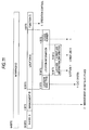
- Fig. 5 is a diagram illustrating an operation sequence when the control terminal 2 controls.the camera 8.
- the control terminal 2 transmits the IPv6 packet for controlling the camera 8 (T1).
- the source IPv6 address contained in a header of the transmitted IPv6 packet is the IPv6 address of the control terminal 2
- the destination IPv6 address is the IPv6 address of the camera 8.
- Detailed information used to control the camera 8 by an upper-level service is contained in application data.
- the camera 8 When receiving the above-described IPv6 packet through the IPv6 network (T2), the camera 8 analyzes the IPv6 packet (T3).
- the source IPv6 address is recognized to be the address of the control terminal 2 from the analysis result.
- the parts other than the function ID 16 (the maker ID 13, the management ID 14, and the device ID 15) in the destination IPv6 address accord with those of the own IPv6 address, it is recognized as the IPv6 packet to be transmitted to itself (T4). Subsequently, a control process defined by the function ID 16 contained in the IPv6 packet is performed (T5).
- the function ID 16 is an ID indicating "motion control" of the camera.
- the motion of the "rightward by 10°” is controlled by the Web access protocol or the like such as the HTTP as the upper-level service, which is contained in the application data.
- the source IPv6 address contained in the IPv6 packet transmitted from the display terminal 3 to the camera 8 is the IPv6 address of the display terminal 3, and the destination IPv6 address is the IPv6 address of the camera 8.
- the controlling of the camera 8 is performed by the Web access protocol such as the HTTP, which is the upper-level service contained in the IPv6 packet, and the management ID 14, the device ID 15, and the function ID 16 assigned in the interface ID 12 of the IPv6 address of the camera 8, which is the destination IPv6 address.
- the function ID 16 is an ID indicating "video data transmission/reception" for the camera 8, when the display terminal 3 "demands transmission of image data" of the camera 8.
- the operations of the "demand for the transmission of the image data” and the “transmitting of the image data” are performed by the Web access protocol such as the HTTP, which is the upper-level service, contained in the application data or a streaming protocol such as RTP.
- Fig. 6 is a diagram illustrating a concept at the time of network communication using the IPv6 address according to the first embodiment.
- the control terminal 2 controls the camera 8.
- the network devices such as the control terminal 2 and the camera 8 connected to each other through the network 6 include address maintenance units 31 and 32 maintaining the IPv6 addresses set and assigned to the respective devices, respectively.
- the address maintenance unit 31 of the control terminal 2 keeps and maintains an IPv6 address 41 containing device type information of the own terminal.
- the address maintenance unit 32 of the camera 8 keeps and maintains an IPv6 address 42 containing device type information of the own terminal.
- a control unit of the control terminal 2 creates and transmits an IPv6 packet 51 containing address information which includes the IPv6 address 41 of the control terminal 2 as a source (control device) and the IPv6 address 42 of the camera 8 as a destination (controlled device) and control information.
- the IPv6 packet 51 is transmitted to the camera 8 through a communication path on the network 6.
- a control unit of the camera 8 analyzes the received IPv6 packet 51 and recognizes that the IPv6 packet is a packet for the own terminal transmitted from the control terminal 2 by the address information of the IPv6 addresses 41 and 42 to perform controlling the own terminal on the basis of the control information.
- controlling performed by a device having no control authority can be excluded by adding the source IPv6 address of a device performing controlling to the control condition.
- masking by the device ID it is possible to perform consistent controlling on a plurality of target device such as all devices capable of "motion control", all video cameras capable of "motion control”, or all video cameras ⁇ (restraining a product) capable of "motion control”.
- IPsec Internet Protocol Security
- the bit number, the bit arrangement, and the bit location in the management ID 14, the device ID 15, the function ID 16, the device type 17, the product type 18, and the product serial number 19 shown in Fig. 2 are just an example, and thus optimized on the basis of the size of a network, a system, a device, or the like, as long as the interface ID is not overlapped in all the network devices.
- the function ID 16 may be located ahead of the device ID 15.
- Fig. 7 is a diagram illustrating a structure of an IPv6 address assigning to a network device according to a second embodiment.
- an IPv6 address different from the IPv6 address according to the first embodiment is assigned to a network device. Since the configuration of the IPv6 network system is the same as that in the first embodiment, the same reference numerals are given and the description is omitted.
- the IPv6 address is 128 bits long and composed of a first-half 64-bit network prefix 11 and a second-half 64-bit interface ID 12.
- the interface ID 12 is composed of a maker ID 13, a management ID 14, a location ID 25, and a function ID 16.
- the management ID 14 corresponds to an example of a number indicating a management system type
- the location ID 25 corresponds to an example of a number indicating location information
- the function ID 16 corresponds to an example of a number indicating function information.
- the former 24 bits of each MAC address held by network device makers are assigned to the maker ID 13 of the 64-bit interface ID 12.
- 4 bits indicating the management system type of a device are assigned to the management ID 14.
- information indicating the management by an installed place (location) is configured so as to be contained as the management system type.
- 8 bits indicating a location name type 27, 20 bits indicating location information 28, 4 bits indicating a device serial number 29 are assigned to the location ID 25.
- 4 bits indicating function of the network device is assigned to the function ID 16.
- Fig. 8 is a diagram illustrating an example of setting items of the location name type, the location information, and the device number when "2" indicating management by the installed place is set in the management ID 14.
- "2" indicating the management by the installed place is set in the management ID 14.
- "1" indicating "a ⁇ system”, "2” indicating "a ⁇ building”, and the like can be set in the location name type 27.
- latitude information "x” indicating a latitude, longitude information "y” indicating a longitude, and the like can be sent in the location information 28.
- latitude information "x” indicating a latitude and the longitude information "y” indicating a longitude can be sent in the location information 28.
- latitude information "x” indicating a latitude and the longitude information "y” indicating a longitude can be sent in the location information 28
- "1", “2”, “3”, and the like indicating respective devices are set in the device number 29.
- floor information " ⁇ floor” indicating a floor, division information " ⁇ division” indicating a division in the floor, and the like can be set in the location information 28.
- the control terminal 2 controls the camera 8
- the source IPv6 address contained in the IPv6 packet transmitted from the control terminal 2 to the camera 8 becomes an IPv6 address of the control terminal 2
- the destination IPv6 address becomes an IPv6 address of the camera 8.
- the controlling of the camera 8 is performed by a Web access protocol such as HTTP, which is an upper-level service contained in the IPv6 packet, and the management ID 14, the location ID 25, and the function ID 16 assigned in the interface ID 12 of the IPv6 address of the camera 8, which is the destination IPv6 address.
- camera 8 recognizes the controlling as the management by the installed place from the management ID 14 on the basis of the received IPv6 packet, recognizes the controlling as the control for the camera 8 itself from the location ID 25, and recognizes control details (control details by the upper-level service) from the function ID 16.
- the control terminal 2 appends information to the IPv6 packet to be transmitted and specifies the camera 8 using the location name type 27, the location information 28, and the device number 29 contained in the device ID 25.
- the control terminal 2 specifies the camera 8 using the information of "the number 1 camera located in the ⁇ division on the ⁇ floor of the ⁇ building".
- Fig. 9 is a diagram illustrating a first example of details set in the interface ID according to the second embodiment.
- the floor information and the division information are used as the location information.
- the management ID 14 indicates management by the installed place
- the location name type 27 indicates the ⁇ building
- the floor information of the former 7 bits of the location information 28 indicates the ⁇ floor
- the division information of the latter 5 bits indicates the ⁇ division.
- the device number 29 indicates the number 1 and the function ID 16 indicates operation control.
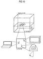
- Fig. 10 is a diagram illustrating an example of the installed place of the network device in the ⁇ building, which is specified by the IPv6 address of the first example shown in Fig. 9 .
- the respective network devices are specified on the basis of the location ID contained in the IPv6 address, when the respective network devices having the device number 1, 2, and 3 are installed in the ⁇ division on the ⁇ floor of the ⁇ building.
- a unique number may be given to every location name type.
- Latitude and longitude coordinate information may be used as the location coordinates by GPS or the like in a case of a location name where the network device is configured in a limited outside division, for example. For example, when each unit of the network device is installed in four directions at a distance of 1 m at the division in four directions at a distance of 1 km, the network devices can be individually recognized by assigning 10 bits to the latitude information and the longitude information.
- Fig. 11 is a diagram illustrating a second example of details set in the interface ID according to the second embodiment.
- the latitude information and the longitude information are used as the location information
- the management ID 14 indicates the management by the installed place
- the location name type 27 indicates the ⁇ system
- the former 10-bit latitude information of the location information 28 indicates the latitude y
- the latter 10-bit longitude information indicates the longitude x.
- the device number 29 indicates the number 1 and the function ID 16 indicates the operation control.
- Fig. 12 is a diagram illustrating an example of the installed place of the network device in the ⁇ system which is specified by the IPv6 address of the second example shown in Fig. 11 .
- the network devices are each specified on the basis of each location ID contained in the IPv6 address, when the network devices of the device numbers 1, 2, and 3 are installed at the division in the four direction at the distance 1 km which lies at a reference point of the latitude y and the longitude x in the ⁇ system.
- the network device can be uniquely identified by assigning 15 bits to the longitude information and 14 bits to the latitude information.
- the control terminal 2 transmits the IPv6 packet for controlling the camera 8 (T1).
- the source IPv6 address contained in a header of the transmitted IPv6 packet is the IPv6 address of the control terminal 2
- the destination IPv6 address is the IPv6 address of the camera 8.
- Detailed information used to control the camera 8 by an upper-level service is contained in application data.
- the camera 8 When receiving the above-described IPv6 packet through the IPv6 network (T2), the camera 8 analyzes the IPv6 packet (T3).
- the source IPv6 address is recognized to be the address of the control terminal 2 from the analysis result.
- the parts other than the function ID 16 (the maker ID 13, the management ID 14, and the location ID 25) in the destination IPv6 address accord with those of the own IPv6 address, it is recognized as the IPv6 packet to be transmitted to itself (T4). Subsequently, a control process defined by the function ID 16 contained in the IPv6 packet is performed (T5).
- the function ID 16 is an ID indicating "motion control" of the camera.
- the motion of the "rightward by 10°” is controlled by the Web access protocol or the like such as the HTTP as the upper-level service, which is contained in the application data.
- the source IPv6 address contained in the IPv6 packet transmitted from the display terminal 3 to the camera 8 is the IPv6 address of the display terminal 3, and the destination IPv6 address is the IPv6 address of the camera 8.
- the controlling of the camera 8 is performed by the Web access protocol such as the HTTP, which is the upper-level service contained in the IPv6 packet, and the management ID 14, the location ID 25, and the function ID 16 assigned in the interface ID 12 of the IPv6 address of the camera 8, which is the destination IPv6 address.
- the function ID 16 is an ID indicating "video data transmission/reception" for the camera 8, when the display terminal 3 "demands transmission of image data" of the camera 8.
- the operations of the "demand for the transmission of the image data” and the “transmitting of the image data” are performed by the Web access protocol such as the HTTP, which is the upper-level service, contained in the application data or a streaming protocol such as RTP.
- controlling performed by a device having no control authority can be excluded by adding the source IPv6 address of a device performing controlling to the control condition.
- masking may be performed by the function ID.
- Figs. 13A to 13C are diagrams illustrating examples of bit arrangement of the interface ID upon performing the masking by the function ID.
- the function ID is arranged behind the location name type. In this case, the masking by the function can be performed on entire terminals of a specific location name.
- the function ID is arranged behind the floor information. In this case, the masking by the function can be performed on entire terminals of the specific location name and the floor.
- the function ID is arranged behind the division information. In this case, the masking by the function can be performed on entire terminals of the specific location name, the floor, and the division.
- the bit number, the bit arrangement, and the bit location in the management ID 14, the location ID 25, the function ID 16, the location name type 27, the location information 28, and the device number 29 shown in Fig. 7 are just an example, and thus optimized on the basis of the size of a network, a system, a location name, or the like, as long as the interface ID is not overlapped in all the network devices.
- the function ID 16 may be located ahead of the location ID 25.
- both the IPv6 address according to the first embodiment and the IPv6 address according to the second embodiment are assigned to one network device. Since the configuration of the IPv6 network system is the same as that in the first embodiment, the same reference numerals are given and the description is omitted.
- the third embodiment it is possible to simultaneously perform different control processes by distinguishing and using the IPv6 addresses by the network device performing control or a control function, when the two IPv6 addresses having the above-described different structures are assigned to one network device.
- control terminal 2 controls the camera 8 using the IPv6 containing the device ID described in the first embodiment and the display terminal 3 controls the camera 8 using the IPv6 address containing the location ID described in the second embodiment.
- the source IPv6 address contained in the IPv6 packet transmitted from the control terminal 2 to the camera 8 is an IPv6 address of the control terminal 2 and the destination IPv6 address is an IPv6 address of the camera 8.
- the controlling of the camera 8 is performed by a Web access protocol such as HTTP, which is an upper-level service contained in the IPv6 packet, and the management ID 14, the device ID 15, and the function ID 16 assigned in the interface ID 12 of the IPv6 address of the camera 8, which is the destination IPv6 address.
- the control terminal 2 specifies the camera 8 using the information of "the number 1 of a video camera ⁇ ".
- the function ID 16 when the camera 8 is fanned "rightward by 10°", the function ID 16 is an ID indicating "motion control" of the camera. Actually, the motion of the "rightward by 10°” is controlled by the Web access protocol or the like such as the HTTP as the upper-level service, which is contained in the application data.
- the source IPv6 address contained in the IPv6 packet transmitted from the display terminal 3 to the camera 8 is the IPv6 address of the display terminal 3, and the destination IPv6 address is the IPv6 address of the camera 8.
- the controlling of the camera 8 is performed by the Web access protocol such as the HTTP, which is the upper-level service contained in the IPv6 packet, and the management ID 14, the location ID 25, and the function ID 16 assigned in the interface ID 12 of the IPv6 address of the camera 8, which is the destination IPv6 address.
- the location information is the ⁇ division (where x is information of coordinates indicating a location) of the ⁇ floor, and the device number is 1, the display terminal 3 specifies the camera 8 using the information of "the number 1 camera located in the ⁇ division on the ⁇ floor of the ⁇ building".
- the function ID 16 is an ID indicating "video data transmission/reception" for the camera 8, when the display terminal 3 "demands transmission of image data" of the camera 8.
- the operations of the "demand for the transmission of the image data” and the “transmitting of the image data” are performed by the Web access protocol such as the HTTP, which is the upper-level service, contained in the application data or a streaming protocol such as RTP.
- Fig. 14 is a diagram illustrating a concept at the time of network communication using the IPv6 address according to the third embodiment.
- the control terminal 2 controls the camera 8 using the IPv6 containing the device ID described in the first embodiment and the display terminal 3 controls the camera 8 using the IPv6 address containing the location ID described in the second embodiment.
- the network devices such as the control terminal 2, the camera 8, and the display terminal 3 connected to each other through the network 6 include address maintenance units 31, 32, and 33 maintaining the IPv6 addresses set and assigned to the respective devices, respectively.
- the address maintenance unit 31 of the control terminal 2 keeps and maintains an IPv6 address 41 containing the device ID of the own terminal and an IPv6 address 61 containing the device ID of the own terminal.
- the address maintenance unit 32 of the camera 8 keeps and maintains an IPv6 address 42 containing the device ID of the own terminal and an IPv6 address 62 containing the device ID of the own terminal.
- the address maintenance unit 33 of the display terminal 3 keeps and maintains an IPv6 address 43 containing the device ID of the own terminal and an IPv6 address 63 containing the device ID of the own terminal.
- control terminal 2 controls the camera 8
- communication is carried out using the IPv6 addresses 41, 42, and 43 containing the respective device type information.
- a control unit of the control terminal 2 creates and transmits an IPv6 packet 51 containing address information which includes the IPv6 address 41 of the control terminal 2 as a source (control device) and the IPv6 address 42 of the camera 8 as a destination (controlled device) and control information.
- the IPv6 packet 51 is transmitted to the camera 8 through a communication path on the network 6.
- a control unit of the camera 8 analyzes the received IPv6 packet 51 and recognizes that the IPv6 packet is a packet for the own terminal by the address information of the IPv6 addresses 41 and 42 to perform controlling the own terminal on the basis of the control information.
- IPv6 addresses 61, 62, and 63 containing the respective device type information.
- a control unit of the display terminal 3 creates and transmits an IPv6 packet 52 containing address information which includes the IPv6 address 63 of the display terminal 3 as a source (control device) and the IPv6 address 62 of the camera 8 as a destination (controlled device) and control information.
- the IPv6 packet 52 is transmitted to the camera 8 through a communication path on the network 6.
- a control unit of the camera 8 analyzes the received IPv6 packet 52 and recognizes that the IPv6 packet is a packet for the own terminal transmitted from the display terminal 3 by the address information of the IPv6 addresses 62 and 63 to perform controlling the own terminal on the basis of the control information.
- the access can be controlled by the device type, the product type, the product serial number, or the function ID, when the IPv6 address containing the management ID, the device ID, and the function ID is used.
- the access can be controlled by the location name type, the location information, the device number, or the function ID, when the IPv6 address containing the management ID, the location ID, and the function ID is used. Accordingly, it is possible to construct the VPN environment using the IPsec and thus improve network security.
- bit number, the bit arrangement, and the bit location in the management ID, the device ID, the function ID, the device type, the product type, and the product serial number are just an example.
- bit number, the bit arrangement, and the bit location in the management ID, the location ID, the function ID, the location name type, the location information, and the device number are just an example. Accordingly, the bit number, the bit arrangement, and the bit location are optimized on the basis of the size of a network, a system, a device, a location name or the like, as long as the interface ID is not overlapped in all the network devices.
- the invention is not limited to these management systems, but the device system may be managed sing time information or the like.
- a management device which manages the network devices using the IPv6 addressed assigned to the network devices may be connected to a network, and thus it is possible to carry out flexible management of the network devices by the management ID of the IPv6 addresses.
- the invention it is possible to obtain an advantage of explicitly identifying network devices without providing a database server having an IPv6 address and an advantage of constructing a high secure network since the network devices as an access target can be managed on the basis of a management system of the network device such as a device type, a function, and a location. Moreover, it is useful for a network device and a network system connected to a network using the IPv6 addresses, an IPv6 address assigning method, and a network device managing method.
Landscapes
- Engineering & Computer Science (AREA)
- Computer Networks & Wireless Communication (AREA)
- Signal Processing (AREA)
- Data Exchanges In Wide-Area Networks (AREA)
- Small-Scale Networks (AREA)
Applications Claiming Priority (2)
| Application Number | Priority Date | Filing Date | Title |
|---|---|---|---|
| JP2006109701A JP4052522B2 (ja) | 2006-04-12 | 2006-04-12 | ネットワーク機器及びネットワーク機器管理方法 |
| PCT/JP2007/056981 WO2007122973A1 (ja) | 2006-04-12 | 2007-03-29 | ネットワーク機器及びネットワークシステム、並びにIPv6アドレス付与方法、ネットワーク機器管理方法 |
Publications (2)
| Publication Number | Publication Date |
|---|---|
| EP2007085A1 true EP2007085A1 (de) | 2008-12-24 |
| EP2007085A4 EP2007085A4 (de) | 2014-05-21 |
Family
ID=38624881
Family Applications (1)
| Application Number | Title | Priority Date | Filing Date |
|---|---|---|---|
| EP07740419.2A Withdrawn EP2007085A4 (de) | 2006-04-12 | 2007-03-29 | Netzvorrichtung und netzsystem, verfahren zur ausgabe von ipv6-adressen und verfahren zur verwaltung einer netzvorrichtung |
Country Status (5)
| Country | Link |
|---|---|
| US (1) | US7779111B2 (de) |
| EP (1) | EP2007085A4 (de) |
| JP (1) | JP4052522B2 (de) |
| CN (1) | CN101421999B (de) |
| WO (1) | WO2007122973A1 (de) |
Cited By (2)
| Publication number | Priority date | Publication date | Assignee | Title |
|---|---|---|---|---|
| WO2014170091A1 (de) * | 2013-04-15 | 2014-10-23 | Siemens Aktiengesellschaft | Ip adressbestimmung |
| EP3139543A4 (de) * | 2014-08-22 | 2017-06-21 | Mitsubishi Heavy Industries, Ltd. | Adresseneinstellvorrichtung, klimaanlage und adresseneinstellverfahren |
Families Citing this family (23)
| Publication number | Priority date | Publication date | Assignee | Title |
|---|---|---|---|---|
| JP5541667B2 (ja) * | 2009-01-30 | 2014-07-09 | キヤノン株式会社 | 管理サーバ、管理方法、監視装置、監視装置の制御方法、及び、プログラム |
| WO2011121485A1 (en) | 2010-03-30 | 2011-10-06 | Koninklijke Philips Electronics N.V. | Network and method for assigning network addresses |
| JP5480719B2 (ja) * | 2010-05-27 | 2014-04-23 | 株式会社Nttドコモ | 端末装置、プレフィックス配布装置、IPv6アドレス生成システム、及びIPv6アドレス生成方法 |
| CN102263653A (zh) * | 2010-05-28 | 2011-11-30 | 中兴通讯股份有限公司 | 一种泛在网设备标识的管理系统及方法 |
| US8406232B2 (en) * | 2010-06-17 | 2013-03-26 | Microsoft Corporation | 4to6 network stack for IPv4 applications |
| JP2012034353A (ja) * | 2010-06-28 | 2012-02-16 | Panasonic Corp | ネットワーク通信装置、通信方法および集積回路 |
| US9391950B2 (en) * | 2012-01-10 | 2016-07-12 | Mitsubishi Electric Corporation | IP address distribution system and IP address distribution method |
| US20140022391A1 (en) * | 2012-07-19 | 2014-01-23 | Saankhya Labs Private Limited | System and method for enabling control of ptz cameras |
| US8982369B2 (en) | 2012-09-25 | 2015-03-17 | Xerox Corporation | Methods, systems and processor-readable media for automatically detecting device movement in a managed service environment |
| CN103220665B (zh) * | 2013-05-07 | 2018-09-28 | 上海斐讯数据通信技术有限公司 | 无线ssid的mac地址分配方法 |
| CN104168151B (zh) * | 2013-05-17 | 2018-06-12 | 中国移动通信集团公司 | 一种基于IPv6的通信方法、监测设备、网关及系统 |
| KR20150106122A (ko) * | 2014-03-11 | 2015-09-21 | 한국전자통신연구원 | IPv6 주소 설정 방법 |
| EP3059930B1 (de) * | 2015-02-18 | 2021-01-06 | Siemens Aktiengesellschaft | Verfahren zur konfiguration eines kommunikationsgeräts eines industriellen automatisierungssystems und kommunikationsgerät |
| CN106340176B (zh) * | 2015-07-09 | 2020-01-17 | 中国电力科学研究院 | 一种智能电表的信息共享方法、智能电表及采集路由器 |
| GB2549549B (en) * | 2016-04-19 | 2020-12-23 | Cisco Tech Inc | A mapping database system for use with content chunks |
| US10447822B2 (en) | 2017-06-19 | 2019-10-15 | Silicon Laboratories, Inc. | DotDot gateway |
| JP6904846B2 (ja) * | 2017-08-07 | 2021-07-21 | キヤノン株式会社 | 通信装置、通信装置の制御方法、および、プログラム |
| US10542585B2 (en) | 2017-09-27 | 2020-01-21 | Silicon Laboratories, Inc. | Gateway using resource directory |
| CN108023973A (zh) * | 2017-11-13 | 2018-05-11 | 下代互联网重大应用技术(北京)工程研究中心有限公司 | 基于地理坐标配置IPv6地址的云网互联的方法及装置 |
| CN108093095B (zh) * | 2017-12-13 | 2020-01-21 | 清华大学 | 将具有短名字的地址字符串转换为IPv6地址的方法及装置 |
| CN114051018B (zh) * | 2021-09-24 | 2024-04-12 | 中盈优创资讯科技有限公司 | 基于网络架构为网络设备分配IPv6地址的方法及装置 |
| CN114401249B (zh) * | 2021-12-08 | 2024-01-23 | 云南电网有限责任公司红河供电局 | 一种IPv6地址分配方法及系统 |
| JP7804832B2 (ja) * | 2022-11-10 | 2026-01-22 | 楽天モバイル株式会社 | 無線ネットワークにおける複数のインターネットプロトコル(ip)アドレスの生成 |
Family Cites Families (19)
| Publication number | Priority date | Publication date | Assignee | Title |
|---|---|---|---|---|
| US8085813B2 (en) * | 1999-10-28 | 2011-12-27 | Lightwaves Systems, Inc. | Method for routing data packets using an IP address based on geo position |
| JP4572476B2 (ja) * | 2001-03-13 | 2010-11-04 | ソニー株式会社 | 通信処理システム、通信処理方法、および通信端末装置、データ転送制御装置、並びにプログラム |
| FI20011075A0 (fi) * | 2001-05-22 | 2001-05-22 | Keijo Laehetkangas | Maantieteellisten paikkatiedon hyödyntäminen internet osoitteissa |
| JP2003051838A (ja) * | 2001-08-07 | 2003-02-21 | Sony Corp | アドレス管理システム、インタフェースid設定処理装置、通信端末装置、およびアドレス管理方法、並びにコンピュータ・プログラム |
| US7873985B2 (en) * | 2002-01-08 | 2011-01-18 | Verizon Services Corp. | IP based security applications using location, port and/or device identifier information |
| JP2003319433A (ja) * | 2002-04-19 | 2003-11-07 | Fujitsu Ltd | 通信装置の設置位置を監視する監視装置および監視システム |
| KR100462864B1 (ko) * | 2002-11-22 | 2004-12-17 | 삼성전자주식회사 | 아이피브이6에서 인터페이스 아이디를 이용한 라우팅테이블 관리 방법 |
| KR100462627B1 (ko) * | 2002-11-27 | 2004-12-23 | 삼성전자주식회사 | IPv6 주소를 이용하여 디바이스를 식별하는 방법 |
| JP3649438B2 (ja) | 2002-11-29 | 2005-05-18 | フリービット株式会社 | インターネット接続システム |
| CN102611596B (zh) * | 2002-11-29 | 2015-02-11 | 飞比特网络股份有限公司 | 网络对应家电 |
| US20040184467A1 (en) | 2003-03-21 | 2004-09-23 | Toshiba Tec Kabushiki Kaisha | Gateway apparatus and IPv6 network system |
| JP2006109701A (ja) | 2003-04-10 | 2006-04-27 | Asahi Glass Co Ltd | 酵母宿主、形質転換体および異種タンパク質の製造方法 |
| US7165722B2 (en) * | 2004-03-10 | 2007-01-23 | Microsoft Corporation | Method and system for communicating with identification tags |
| CN100425024C (zh) * | 2004-07-06 | 2008-10-08 | 北京航空航天大学 | IPv6因特网网络拓扑自动发现方法 |
| KR20060011533A (ko) * | 2004-07-30 | 2006-02-03 | 엘지전자 주식회사 | 랜상의 아이피브이6 서브넷 관리방법 |
| US20060077984A1 (en) * | 2004-10-13 | 2006-04-13 | Matsushita Electric Industrial Co., Ltd. | Gateway apparatus, server apparatus, and method for address management |
| US7941512B2 (en) * | 2004-12-13 | 2011-05-10 | Cisco Technology, Inc. | Use of IPv6 in access networks |
| KR100693046B1 (ko) * | 2004-12-20 | 2007-03-12 | 삼성전자주식회사 | 동적 주소를 할당하고 그 동적 주소를 이용하여라우팅하는 네트워크 시스템 및 그 방법 |
| US20070081544A1 (en) * | 2005-10-12 | 2007-04-12 | Matsushita Electric Industrial Co., Ltd. | Gateway apparatus, server apparatus, and method for address management |
-
2006
- 2006-04-12 JP JP2006109701A patent/JP4052522B2/ja not_active Expired - Fee Related
-
2007
- 2007-03-29 US US12/295,105 patent/US7779111B2/en not_active Expired - Fee Related
- 2007-03-29 WO PCT/JP2007/056981 patent/WO2007122973A1/ja not_active Ceased
- 2007-03-29 EP EP07740419.2A patent/EP2007085A4/de not_active Withdrawn
- 2007-03-29 CN CN2007800133054A patent/CN101421999B/zh not_active Expired - Fee Related
Cited By (2)
| Publication number | Priority date | Publication date | Assignee | Title |
|---|---|---|---|---|
| WO2014170091A1 (de) * | 2013-04-15 | 2014-10-23 | Siemens Aktiengesellschaft | Ip adressbestimmung |
| EP3139543A4 (de) * | 2014-08-22 | 2017-06-21 | Mitsubishi Heavy Industries, Ltd. | Adresseneinstellvorrichtung, klimaanlage und adresseneinstellverfahren |
Also Published As
| Publication number | Publication date |
|---|---|
| CN101421999B (zh) | 2012-06-20 |
| US20090177762A1 (en) | 2009-07-09 |
| CN101421999A (zh) | 2009-04-29 |
| JP2007288234A (ja) | 2007-11-01 |
| WO2007122973A1 (ja) | 2007-11-01 |
| EP2007085A4 (de) | 2014-05-21 |
| US7779111B2 (en) | 2010-08-17 |
| JP4052522B2 (ja) | 2008-02-27 |
Similar Documents
| Publication | Publication Date | Title |
|---|---|---|
| US7779111B2 (en) | Network device and network device managing method | |
| US10778637B2 (en) | Method for naming domain name system (DNS) for internet of things (IoT) device | |
| CN101558602A (zh) | 网络设备定位和配置 | |
| CN114503616B (zh) | 中继装置、车载通信系统、车辆及车载通信方法 | |
| CN100481832C (zh) | 通信装置、边界路由器装置、服务器装置、通信系统和通信方法 | |
| EP2733895B1 (de) | Relaisserver und relaiskommunikationssystem | |
| WO2014037779A1 (en) | End-to-end communication in sensor network | |
| CN103765945A (zh) | 无线通信装置及无线通信系统 | |
| CN104937573B (zh) | 设备管理装置、设备管理系统以及设备管理方法 | |
| US11848796B2 (en) | Aggregator apparatus for standardized access to a plurality of network segments of a field bus system | |
| EP2787692B1 (de) | Relaisserver mit steuerungseinheit, die zum setzen einer überlap-detektion-bedingung angepasst ist | |
| US7706371B1 (en) | Domain based routing for managing devices operating behind a network address translator | |
| CN108259295B (zh) | Mac地址同步方法及装置 | |
| CN107124312A (zh) | 网络中设备配置的方法和装置 | |
| JP2000312211A (ja) | 通信装置 | |
| US10050929B2 (en) | Connection setting information managing system | |
| JP3406768B2 (ja) | パケット転送方法およびパケット転送装置 | |
| EP4241415B1 (de) | Verfahren, vorrichtung und system zur bereitstellung einer vielzahl von operativ verbundenen knotenvorrichtungen in einem netzwerk | |
| JP5213070B2 (ja) | 無線通信網接続システム、無線通信網接続方法 | |
| US20250317443A1 (en) | Management of private networks over multiple local networks | |
| KR102833703B1 (ko) | 홈네트워크 시스템에서 vpn 게이트웨이의 자동 ip 부여방법 및 vpn 게이트웨이 | |
| CN104956640A (zh) | 用于控制对数据的同时访问的方法 | |
| CN107547395B (zh) | 一种报文传输方法、装置及机器可读存储介质 | |
| KR20120000171A (ko) | 동일 가입자 주소의 처리 기능을 갖는 가상 사설 통신 시스템 및 그 방법 | |
| JP2007158512A (ja) | Ipネットワークシステム |
Legal Events
| Date | Code | Title | Description |
|---|---|---|---|
| PUAI | Public reference made under article 153(3) epc to a published international application that has entered the european phase |
Free format text: ORIGINAL CODE: 0009012 |
|
| 17P | Request for examination filed |
Effective date: 20080930 |
|
| AK | Designated contracting states |
Kind code of ref document: A1 Designated state(s): DE FR GB |
|
| RBV | Designated contracting states (corrected) |
Designated state(s): DE FR GB |
|
| DAX | Request for extension of the european patent (deleted) | ||
| A4 | Supplementary search report drawn up and despatched |
Effective date: 20140425 |
|
| RIC1 | Information provided on ipc code assigned before grant |
Ipc: H04L 12/70 20130101AFI20140519BHEP |
|
| STAA | Information on the status of an ep patent application or granted ep patent |
Free format text: STATUS: THE APPLICATION IS DEEMED TO BE WITHDRAWN |
|
| 18D | Application deemed to be withdrawn |
Effective date: 20141125 |