EP2007181B1 - Controleur pour robot industriel - Google Patents
Controleur pour robot industriel Download PDFInfo
- Publication number
- EP2007181B1 EP2007181B1 EP07738344A EP07738344A EP2007181B1 EP 2007181 B1 EP2007181 B1 EP 2007181B1 EP 07738344 A EP07738344 A EP 07738344A EP 07738344 A EP07738344 A EP 07738344A EP 2007181 B1 EP2007181 B1 EP 2007181B1
- Authority
- EP
- European Patent Office
- Prior art keywords
- housing
- hinge
- controller
- internal devices
- opened
- Prior art date
- Legal status (The legal status is an assumption and is not a legal conclusion. Google has not performed a legal analysis and makes no representation as to the accuracy of the status listed.)
- Not-in-force
Links
Images


Classifications
-
- B—PERFORMING OPERATIONS; TRANSPORTING
- B25—HAND TOOLS; PORTABLE POWER-DRIVEN TOOLS; MANIPULATORS
- B25J—MANIPULATORS; CHAMBERS PROVIDED WITH MANIPULATION DEVICES
- B25J13/00—Controls for manipulators
- B25J13/06—Control stands, e.g. consoles, switchboards
-
- H—ELECTRICITY
- H05—ELECTRIC TECHNIQUES NOT OTHERWISE PROVIDED FOR
- H05K—PRINTED CIRCUITS; CASINGS OR CONSTRUCTIONAL DETAILS OF ELECTRIC APPARATUS; MANUFACTURE OF ASSEMBLAGES OF ELECTRICAL COMPONENTS
- H05K7/00—Constructional details common to different types of electric apparatus
- H05K7/14—Mounting supporting structure in casing or on frame or rack
- H05K7/1462—Mounting supporting structure in casing or on frame or rack for programmable logic controllers [PLC] for automation or industrial process control
- H05K7/1467—PLC mounted in a cabinet or chassis
-
- H—ELECTRICITY
- H02—GENERATION; CONVERSION OR DISTRIBUTION OF ELECTRIC POWER
- H02B—BOARDS, SUBSTATIONS OR SWITCHING ARRANGEMENTS FOR THE SUPPLY OR DISTRIBUTION OF ELECTRIC POWER
- H02B1/00—Frameworks, boards, panels, desks, casings; Details of substations or switching arrangements
- H02B1/26—Casings; Parts thereof or accessories therefor
- H02B1/30—Cabinet-type casings; Parts thereof or accessories therefor
Definitions
- the present invention relates to an apparatus of downsizing the structure of a controller for an industrial robot according to the preamble of independent claim 1.
- an upper face portion of a housing of the controller is composed being freely opened and closed by a hinge and further an intermediate partition plate, which is opened and closed by a hinge, is provided in the housing of the controller.
- Concerning this controller for example, refer to JP-A-58-181591 .
- the following structure is disclosed.
- an upper face portion is supported by a hinge being freely opened and closed like a door opened upward.
- JP-A-4-365581 the welding electric power source and the robot controller are accommodated in the same housing. Therefore, the entire unit may be downsized and the cables may be orderly laid. Further, when the welding electric power source is slid, the unit may be easily checked and maintained.
- a switch board housing is disclosed comprising flexible compartments with a hingely connected housing capable of functioning as closing means for adjacent housings.
- the intermediate partition plate and the hinge are arranged inside the housing of the controller, even when the intermediate partition plate is opened, the devices such as a motor drive unit and others, which are arranged in the inner part, must be checked and maintained in the small housing. Further, in the actual structure, in the periphery of the hinge of the intermediate partition plate, cables connected to the devices attached onto the intermediate partition plate are arranged. Therefore, even when a sufficiently large hinge rotation angle is provided, the intermediate partition plate may not be opened by a sufficiently large angle being obstructed by a bending reaction force generated by the cables. Accordingly, the working efficiency may not be enhanced and further it is difficult to maintain the safety of working.
- the devices attached to the intermediate partition plate must be arranged so that they may not interfere with the other devices when the intermediate partition plate is opened. Therefore, it is impossible to arbitrarily arrange the devices and the space in the housing may not be effectively utilized.
- the conventional robot controller described in JP-A-4-365581 it may be thought that the devices may be easily checked and maintained when the internal devices such as a welding electric power source are made into a sliding type.
- the sliding type is disadvantageous in that distances of moving the cables are increased. Therefore, it is necessary to compose the devices so that the cables are not dragged. That is, in the case of the sliding type, there is a high possibility that the cables fall off and damage.
- the present invention has been accomplished to solve the above problems. It is an object of the present invention to provide a robot controller used for an industrial robot capable of ensuring the efficiency and safety of working and also capable of sufficiently utilizing a space in the housing into which the devices are attached.
- a controller for an industrial robot is provided with a first housing which accommodates a first internal device, a second housing which accommodates a second internal device, and a front door which is supported to open and close by a first hinge which is provided on a side of the first housing, wherein a second hinge is provided on the sides of the first housing and the second housing, and second housing is supported to open and close the entire first housing by the second hinge, wherein the controller for the industrial robot is provided with an accommodating portion which protrudes from a front face lower portion of the second housing to a lower portion of the first housing, wherein the accommodating portion is connected to an interior space of the housing and accommodates a third internal device.
- the third internal device is exposed to an opening which is provided on an upper face of the accommodating portion when the first housing is opened the second housing by the second hinge.
- a robot body is coupled to the controller for the industrial robot.
- the housing of the robot controller is divided into two portions in the longitudinal direction and the divided housings are supported by a hinge. Therefore, the front housing is moved and separated being rotated by the hinge. Accordingly, unlike the conventional structure in which the partition plate is opened and closed inside the housing and the peripheral housing is not moved at the time of the maintenance of the internal devices accommodated in the rear housing, in the structure of the present invention, the maintenance work is not obstructed by the housing itself. Accordingly, the working efficiency is not lowered.
- an installation space of the robot system may be reduced when a robot system is built.
- the robot controller of the present invention is usually connected to an industrial robot body by cables and composed as a robot system.
- the controller is driven by a servo motor and others built in the robot body and controlled desirably.
- a structure of the robot controller of the present invention includes: a first housing 1 for accommodating the first internal devices 6; a second housing 2 for accommodating the second internal devices 7; an accommodating portion 11 provided below the first housing 1; and a front door 3 arranged on the front face of the first housing 1.
- the front door 3 is opened and closed with respect to the first housing 1 and the first internal devices 6.
- the front door 3 is supported by the first hinge 4 so that it may be freely opened and closed at either the right or the left of the first housing 1.
- the front door 3 is opened by the first hinge 4, it is possible to take a front view of the first internal devices 6.
- the front door 3 is provided with an emergency switch 16 and others. Cables 13 connected to the emergency switch 16 and others are connected from the side (on the side of an opening and closing fulcrum), on which the first hinge 4 is provided, to the first internal devices 6 along the back face of the front door 3.
- the front door 3 is provided with a main electric power switch 17 and a screw 18. The front door 3 may be fixed to the first housing 11 by the screw 18.
- Reference numeral 5 is a second hinge.
- the second hinge 5 supports the first door 1 itself so that the first door 1 may be freely opened and closed to either the right or the left of the second housing 2 like a door. That is, the entire first housing 1 is composed so that it may be freely opened and closed with respect to the second housing 2 being rotated round the second hinge 5.
- the first housing 1 may be fixed to the second housing 2 by a screw not shown in the inner portion of the housing. This screw is similar to the screw 18 described above.
- the first housing 1 functions as a front door, which is like the front door 3 with respect to the first housing 1, with respect to the second housing 2 and the second internal devices 7.
- the back plate 14 is arranged on the back face of the first housing 1.
- the first internal devices 6 described before are fixed onto this back plate 14.
- the cables 15 connected to the first internal devices 6 are connected to the second internal devices 7 from the side (the opening and closing fulcrum side), on which the second hinge 5 is arranged, through the opening 14a of the back plate 14.
- Reference numeral 11 is an accommodating portion for accommodating the third internal devices 8 and the cable 9.
- the accommodating portion 11 is integrated with the second housing 2 into one body and protruded from a front face lower portion of the second housing 2 to a lower portion of the first housing 1.
- An inner space of the second housing 2 is connected to that of the accommodating portion 11.
- the accommodating portion 11 is composed in such a manner that an area of the accommodating portion 11 in the case of taking a plan view of the accommodating portion 11 from an upper face substantially coincides with an area of the lower face of the first housing 1.
- An upper surface of the accommodating portion 11 is open by the opening 12.
- the third internal devices 8 and the cables 9 are accommodated in the accommodating portion 11.
- the accommodating portion 11 may be composed so that it may be separated from the second housing 2.
- the first internal devices 6 include a CPU for controlling a robot.
- the second internal devices 7 include a drive control unit for driving a servo motor built in the robot body.
- the third internal devices 8 include a terminal table and an optional device. The first to third internal devices described above are connected to each other by cables.
- the robot controller of the present invention composed as described above, first of all, when the front door 3 is opened being rotated round the first hinge 4 in Fig. 1 , the first internal devices 6 appear as shown in Fig. 2 . Due to the foregoing, a worker may have access to the first internal devices 6. Therefore, the worker may easily check and maintain the first internal devices 6.
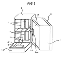
- the second internal devices 7 appear as shown in Fig. 3 . Due to the foregoing, a worker may have access to the second internal devices 7. Therefore, the worker may easily check and maintain the second internal devices 7. According to this structure, since the first housing 1, in which the first internal devices 6 are accommodated, is supported by the second hinge 5 being freely opened and closed, the entire first housing 1 is separated from the second housing. Therefore, unlike the conventional structure in which the partition plate arranged in the housing is opened and closed by the hinge provided in the housing, it is possible to check and maintain devices such as the second internal devices arranged in the inner portion of the front door without being obstructed by the housing.
- the third internal devices 8 appear from the upper face opening 12 of the accommodating portion 11 located in a lower portion of the first housing 1. Due to the foregoing, a worker may have access to the third internal devices 8 and execute a maintenance work.
- the third internal devices 8 include a terminal table or an optional device, it is easy for the worker to execute a screwing work from the upper face. Therefore, the work may be easily accomplished. Even in the case where an optional device is added after the robot controller has been installed, it is possible to execute the work from the upper face. Therefore, the work may be easily accomplished. Further, cables of which the length is too long may be accommodated in the accommodating portion 11 being hung.
- the present invention may be applied to not only the constitution of a robot controller but also the constitution of a controller of a machine tool or a common industrial machine.
Landscapes
- Engineering & Computer Science (AREA)
- Automation & Control Theory (AREA)
- Microelectronics & Electronic Packaging (AREA)
- Robotics (AREA)
- Mechanical Engineering (AREA)
- Power Engineering (AREA)
- Casings For Electric Apparatus (AREA)
- Manipulator (AREA)
- Numerical Control (AREA)
- Patch Boards (AREA)
Abstract
Claims (3)
- Contrôleur (20) pour un robot industriel comprenant :un premier boîtier (1) qui reçoit un premier dispositif interne (6) ;un deuxième boîtier (2) qui reçoit un deuxième dispositif interne (7) ; etune porte avant (3) qui est supportée, de manière à s'ouvrir et se fermer, par une première charnière (4) prévue sur un côté du premier boîtier (1),étant précisé qu'une deuxième charnière (5) est prévue sur les côtés du premier boîtier (1) et du deuxième boîtier (2), et que le deuxième boîtier (2) est supporté pour que tout le premier boîtier (1) s'ouvre et se ferme grâce à la deuxième charnière (5),caractérisé par une partie de réception (11) qui dépasse d'une partie inférieure de la face avant du deuxième boîtier (2), sous le premier boîtier, et la partie de réception (11) est reliée à un espace intérieur du deuxième boîtier (2) et reçoit un troisième dispositif interne (8).
- Contrôleur pour le robot industriel selon la revendication 1, étant précisé que le troisième dispositif interne (8) est exposé à une ouverture qui est prévue sur une face supérieure de la partie de réception (11) quand le premier boîtier (1) est ouvert par rapport au deuxième boîtier (2) par la deuxième charnière (3).
- Système de robot selon la revendication 1 ou 2, étant précisé qu'un corps de robot (19) est accouplé au contrôleur (20) pour le robot industriel.
Applications Claiming Priority (2)
| Application Number | Priority Date | Filing Date | Title |
|---|---|---|---|
| JP2006106198 | 2006-04-07 | ||
| PCT/JP2007/054872 WO2007122903A1 (fr) | 2006-04-07 | 2007-03-13 | Contrôleur pour robot industriel |
Publications (4)
| Publication Number | Publication Date |
|---|---|
| EP2007181A2 EP2007181A2 (fr) | 2008-12-24 |
| EP2007181A9 EP2007181A9 (fr) | 2009-07-08 |
| EP2007181A4 EP2007181A4 (fr) | 2010-06-09 |
| EP2007181B1 true EP2007181B1 (fr) | 2011-12-28 |
Family
ID=38624814
Family Applications (1)
| Application Number | Title | Priority Date | Filing Date |
|---|---|---|---|
| EP07738344A Not-in-force EP2007181B1 (fr) | 2006-04-07 | 2007-03-13 | Controleur pour robot industriel |
Country Status (6)
| Country | Link |
|---|---|
| US (1) | US8141962B2 (fr) |
| EP (1) | EP2007181B1 (fr) |
| JP (1) | JP4600872B2 (fr) |
| KR (1) | KR100996520B1 (fr) |
| CN (1) | CN101406115B (fr) |
| WO (1) | WO2007122903A1 (fr) |
Families Citing this family (15)
| Publication number | Priority date | Publication date | Assignee | Title |
|---|---|---|---|---|
| JP5291388B2 (ja) * | 2008-06-05 | 2013-09-18 | 三菱重工業株式会社 | コントロールボックスおよび空気調和機の室外機 |
| JP2011031316A (ja) * | 2009-07-30 | 2011-02-17 | Yaskawa Electric Corp | 制御装置 |
| WO2012039095A1 (fr) * | 2010-09-24 | 2012-03-29 | パナソニック株式会社 | Dispositif de commande |
| JP2012110973A (ja) * | 2010-11-19 | 2012-06-14 | Yaskawa Electric Corp | 制御装置 |
| JP5765356B2 (ja) * | 2013-03-19 | 2015-08-19 | 株式会社安川電機 | 筐体 |
| JP6207409B2 (ja) * | 2014-01-24 | 2017-10-04 | ヤマハ発動機株式会社 | コントローラ |
| US9192231B1 (en) * | 2014-02-12 | 2015-11-24 | Daniel W. Steffen | Curio cabinet with concealed gun rack |
| EP3107360A1 (fr) * | 2015-06-15 | 2016-12-21 | Comau S.p.A. | Dispositif de conversion d'un module d'une station de commande de robots industriels dans une unité de commande indépendante |
| DE102016100634B4 (de) * | 2016-01-15 | 2019-09-12 | Avl Emission Test Systems Gmbh | Schaltschrank für Abgasmessanlagen |
| JP1627719S (fr) * | 2017-09-29 | 2019-03-25 | ||
| US11303074B2 (en) * | 2020-06-22 | 2022-04-12 | Google Llc | Enclosures to constrain the location of connectors in automation applications |
| CN111993445B (zh) * | 2020-07-24 | 2021-11-30 | 珠海格力电器股份有限公司 | 伺服驱动柜及机器人系统 |
| DE102020134288A1 (de) * | 2020-12-18 | 2022-06-23 | Wipotec Science & Innovation Gmbh | Schaltschrankanordnung |
| JP2023154354A (ja) * | 2022-04-06 | 2023-10-19 | パナソニックIpマネジメント株式会社 | ロボット制御装置 |
| JP2025076202A (ja) * | 2023-11-01 | 2025-05-15 | ギガフォトン株式会社 | 電装ボックス及び極端紫外光生成装置 |
Family Cites Families (15)
| Publication number | Priority date | Publication date | Assignee | Title |
|---|---|---|---|---|
| US1241615A (en) * | 1916-08-07 | 1917-10-02 | Homer J Farrow | Multiple-section fireproof cabinet for duplicate sales-books and the like. |
| US4240222A (en) * | 1978-12-26 | 1980-12-23 | Covington Dorris L | Tackle box |
| JPS5615084U (fr) * | 1979-07-13 | 1981-02-09 | ||
| JPS58181591A (ja) | 1982-04-17 | 1983-10-24 | ヤマハ発動機株式会社 | 工業用ロボツトの制御盤構造 |
| GB8729952D0 (en) * | 1987-12-23 | 1988-02-03 | British Telecomm | Mounting assembly for optical equipment |
| US4978001A (en) * | 1989-11-20 | 1990-12-18 | Nelson Elsie C | Jewelry closet |
| JP2674358B2 (ja) | 1991-06-11 | 1997-11-12 | 松下電器産業株式会社 | アーク溶接電源内蔵ロボットコントローラ |
| JPH05336623A (ja) | 1992-06-04 | 1993-12-17 | Fuji Electric Co Ltd | 多層形配電盤 |
| US5484219A (en) * | 1994-02-22 | 1996-01-16 | The Babcock & Wilcox Company | Six-degree-of-freedom compliancy/breakaway device |
| JPH07232282A (ja) * | 1994-02-25 | 1995-09-05 | Obara Kk | C型溶接ガンの制御装置 |
| US5573319A (en) * | 1995-03-28 | 1996-11-12 | Cooper Industries, Inc. | Transformer cabinet having formed channel edges |
| US5949209A (en) * | 1996-09-11 | 1999-09-07 | Nachi-Fujikoshi Corp. | Explosion-proof painting robot |
| US6066802A (en) * | 1998-09-21 | 2000-05-23 | Abb Power T&D Company Inc. | Safety enclosure system for a transformer |
| US6642481B2 (en) * | 2001-05-11 | 2003-11-04 | Illinois Tool Works Inc. | Integrated welding control and power supply using phased control power technology |
| US7838142B2 (en) * | 2006-02-09 | 2010-11-23 | Scheucher Karl F | Scalable intelligent power supply system and method |
-
2007
- 2007-03-13 EP EP07738344A patent/EP2007181B1/fr not_active Not-in-force
- 2007-03-13 WO PCT/JP2007/054872 patent/WO2007122903A1/fr not_active Ceased
- 2007-03-13 JP JP2008512012A patent/JP4600872B2/ja active Active
- 2007-03-13 KR KR1020087016299A patent/KR100996520B1/ko not_active Expired - Fee Related
- 2007-03-13 CN CN2007800096322A patent/CN101406115B/zh not_active Expired - Fee Related
- 2007-03-13 US US12/296,229 patent/US8141962B2/en not_active Expired - Fee Related
Also Published As
| Publication number | Publication date |
|---|---|
| US20100156253A1 (en) | 2010-06-24 |
| US8141962B2 (en) | 2012-03-27 |
| KR20080078870A (ko) | 2008-08-28 |
| JP4600872B2 (ja) | 2010-12-22 |
| JPWO2007122903A1 (ja) | 2009-09-03 |
| EP2007181A9 (fr) | 2009-07-08 |
| KR100996520B1 (ko) | 2010-11-24 |
| CN101406115B (zh) | 2010-11-10 |
| EP2007181A2 (fr) | 2008-12-24 |
| CN101406115A (zh) | 2009-04-08 |
| EP2007181A4 (fr) | 2010-06-09 |
| WO2007122903A1 (fr) | 2007-11-01 |
Similar Documents
| Publication | Publication Date | Title |
|---|---|---|
| EP2007181B1 (fr) | Controleur pour robot industriel | |
| US20130207606A1 (en) | Charging station for use in charging electrically powered vehicles | |
| EP1953324B1 (fr) | Appareil d'ouverture/de fermeture automatique pour véhicule | |
| EP2172370A1 (fr) | Dispositif d'alimentation électrique pour porte coulissante | |
| CN101235696A (zh) | 车辆用自动开闭装置 | |
| US20210364068A1 (en) | Actuator comprising anti-backbend chain | |
| RU2006103080A (ru) | Лифт с встроенным в крышу кабины электрооборудованием | |
| EP1793290A1 (fr) | Dispositif de commande de robot et système de robot | |
| US8319119B2 (en) | Section for a window, door or facade element comprising an electric cable | |
| KR102334137B1 (ko) | 배전 케이블 접속부 단자부식 방지 장치 | |
| EP2759030B1 (fr) | Panneau avec interrupteur pivotable | |
| KR102582142B1 (ko) | 가공배전선로용 복합기능 고정기구 | |
| US8464468B2 (en) | Drive unit for garage doors with universal electric connection options | |
| JP5212551B2 (ja) | 制御装置 | |
| JP5241225B2 (ja) | エレベータ制御盤 | |
| CN101235698A (zh) | 车辆用自动开闭装置 | |
| JP4971814B2 (ja) | 車両用自動開閉装置 | |
| CN213341231U (zh) | 一种前开门控制柜 | |
| KR20040095066A (ko) | 공장용 환기창문의 자동 개폐장치 | |
| CN100519101C (zh) | 机器人控制装置及机器人系统 | |
| US20190093406A1 (en) | Guiding rail for guiding a door leaf between an opening position and a closing position in relation to a door opening in a wall | |
| JP2005036499A (ja) | 車庫用扉 | |
| KR100664235B1 (ko) | 가동형 보호창을 구비한 휴대용 단말기 | |
| KR200284501Y1 (ko) | 전자제어반장치의 감시창 구조 | |
| KR100420364B1 (ko) | 냉장고의 컨트롤러부 커버 |
Legal Events
| Date | Code | Title | Description |
|---|---|---|---|
| PUAI | Public reference made under article 153(3) epc to a published international application that has entered the european phase |
Free format text: ORIGINAL CODE: 0009012 |
|
| PUAB | Information related to the publication of an a document modified or deleted |
Free format text: ORIGINAL CODE: 0009199EPPU |
|
| 17P | Request for examination filed |
Effective date: 20081007 |
|
| AK | Designated contracting states |
Kind code of ref document: A2 Designated state(s): DE SE |
|
| DAX | Request for extension of the european patent (deleted) | ||
| RBV | Designated contracting states (corrected) |
Designated state(s): DE SE |
|
| A4 | Supplementary search report drawn up and despatched |
Effective date: 20100512 |
|
| GRAP | Despatch of communication of intention to grant a patent |
Free format text: ORIGINAL CODE: EPIDOSNIGR1 |
|
| RIC1 | Information provided on ipc code assigned before grant |
Ipc: B25J 13/06 20060101ALI20110628BHEP Ipc: H05K 5/02 20060101AFI20110628BHEP |
|
| GRAS | Grant fee paid |
Free format text: ORIGINAL CODE: EPIDOSNIGR3 |
|
| GRAA | (expected) grant |
Free format text: ORIGINAL CODE: 0009210 |
|
| AK | Designated contracting states |
Kind code of ref document: B1 Designated state(s): DE SE |
|
| REG | Reference to a national code |
Ref country code: DE Ref legal event code: R096 Ref document number: 602007019681 Country of ref document: DE Effective date: 20120308 |
|
| REG | Reference to a national code |
Ref country code: SE Ref legal event code: TRGR |
|
| PLBE | No opposition filed within time limit |
Free format text: ORIGINAL CODE: 0009261 |
|
| STAA | Information on the status of an ep patent application or granted ep patent |
Free format text: STATUS: NO OPPOSITION FILED WITHIN TIME LIMIT |
|
| 26N | No opposition filed |
Effective date: 20121001 |
|
| REG | Reference to a national code |
Ref country code: DE Ref legal event code: R097 Ref document number: 602007019681 Country of ref document: DE Effective date: 20121001 |
|
| PGFP | Annual fee paid to national office [announced via postgrant information from national office to epo] |
Ref country code: DE Payment date: 20160308 Year of fee payment: 10 |
|
| PGFP | Annual fee paid to national office [announced via postgrant information from national office to epo] |
Ref country code: SE Payment date: 20160311 Year of fee payment: 10 |
|
| REG | Reference to a national code |
Ref country code: DE Ref legal event code: R119 Ref document number: 602007019681 Country of ref document: DE |
|
| REG | Reference to a national code |
Ref country code: SE Ref legal event code: EUG |
|
| PG25 | Lapsed in a contracting state [announced via postgrant information from national office to epo] |
Ref country code: SE Free format text: LAPSE BECAUSE OF NON-PAYMENT OF DUE FEES Effective date: 20170314 |
|
| PG25 | Lapsed in a contracting state [announced via postgrant information from national office to epo] |
Ref country code: DE Free format text: LAPSE BECAUSE OF NON-PAYMENT OF DUE FEES Effective date: 20171003 |