EP2007184A2 - Système de gestion thermique intégrée et procédé correspondant - Google Patents
Système de gestion thermique intégrée et procédé correspondant Download PDFInfo
- Publication number
- EP2007184A2 EP2007184A2 EP08157713A EP08157713A EP2007184A2 EP 2007184 A2 EP2007184 A2 EP 2007184A2 EP 08157713 A EP08157713 A EP 08157713A EP 08157713 A EP08157713 A EP 08157713A EP 2007184 A2 EP2007184 A2 EP 2007184A2
- Authority
- EP
- European Patent Office
- Prior art keywords
- heat
- cooling fluid
- heat exchanger
- thermal management
- release
- Prior art date
- Legal status (The legal status is an assumption and is not a legal conclusion. Google has not performed a legal analysis and makes no representation as to the accuracy of the status listed.)
- Withdrawn
Links
Images


Classifications
-
- H—ELECTRICITY
- H05—ELECTRIC TECHNIQUES NOT OTHERWISE PROVIDED FOR
- H05K—PRINTED CIRCUITS; CASINGS OR CONSTRUCTIONAL DETAILS OF ELECTRIC APPARATUS; MANUFACTURE OF ASSEMBLAGES OF ELECTRICAL COMPONENTS
- H05K7/00—Constructional details common to different types of electric apparatus
- H05K7/20—Modifications to facilitate cooling, ventilating, or heating
- H05K7/2089—Modifications to facilitate cooling, ventilating, or heating for power electronics, e.g. for inverters for controlling motor
- H05K7/20945—Thermal management, e.g. inverter temperature control
-
- F—MECHANICAL ENGINEERING; LIGHTING; HEATING; WEAPONS; BLASTING
- F03—MACHINES OR ENGINES FOR LIQUIDS; WIND, SPRING, OR WEIGHT MOTORS; PRODUCING MECHANICAL POWER OR A REACTIVE PROPULSIVE THRUST, NOT OTHERWISE PROVIDED FOR
- F03D—WIND MOTORS
- F03D80/00—Details, components or accessories not provided for in groups F03D1/00 - F03D17/00
- F03D80/60—Cooling or heating of wind motors
-
- F—MECHANICAL ENGINEERING; LIGHTING; HEATING; WEAPONS; BLASTING
- F28—HEAT EXCHANGE IN GENERAL
- F28D—HEAT-EXCHANGE APPARATUS, NOT PROVIDED FOR IN ANOTHER SUBCLASS, IN WHICH THE HEAT-EXCHANGE MEDIA DO NOT COME INTO DIRECT CONTACT
- F28D15/00—Heat-exchange apparatus with the intermediate heat-transfer medium in closed tubes passing into or through the conduit walls ; Heat-exchange apparatus employing intermediate heat-transfer medium or bodies
-
- Y—GENERAL TAGGING OF NEW TECHNOLOGICAL DEVELOPMENTS; GENERAL TAGGING OF CROSS-SECTIONAL TECHNOLOGIES SPANNING OVER SEVERAL SECTIONS OF THE IPC; TECHNICAL SUBJECTS COVERED BY FORMER USPC CROSS-REFERENCE ART COLLECTIONS [XRACs] AND DIGESTS
- Y02—TECHNOLOGIES OR APPLICATIONS FOR MITIGATION OR ADAPTATION AGAINST CLIMATE CHANGE
- Y02P—CLIMATE CHANGE MITIGATION TECHNOLOGIES IN THE PRODUCTION OR PROCESSING OF GOODS
- Y02P80/00—Climate change mitigation technologies for sector-wide applications
- Y02P80/10—Efficient use of energy, e.g. using compressed air or pressurized fluid as energy carrier
Definitions
- the invention relates generally to thermal management systems and more specifically, to thermal management in electrical systems.
- An electrical system in a commonly used application such as a wind turbine includes electrical components such as transformers, switch gear, power converters and electric machines that are located inside a confined compartment or a containment such as a tower or a nacelle or an external building.
- Transformers, power converters and electric machines are typically large scale equipment and generate undesirable amount of losses. The losses are released as heat during operation.
- the transformer and the power converters are usually in close proximity to each other. Further, the power rating of the electric equipment is determined by the ability to homogeneously cool it. Hence, it is desirable to remove the heat from the containment to avoid excessive heating of the electrical components leading to a failure.
- a certain technique includes a forced convection device such as a fan.
- a forced convection system generally requires large air ducts and filters for the entry of cool air and to expel hot air from the tower.
- a fan may generate undesirable levels of noise and cooling fins add to the size and weight of equipment.
- Another cooling system typically used includes, but is not limited to, a liquid cooled system. The liquid cooled system enables reducing the size of the electrical system by eliminating large air ducts and cooling fins.
- a typical electrical system may include several electrical components having different cooling methods.
- An example is a forced air cooled transformer and a water cooled power converter system. Therefore, having independent and different cooling system for each of the electrical components adds to size of an electrical system and cost of design.
- an integrated thermal management system includes a first device configured to release a first heat loss and coupled to an integrated cooling system.
- the system also includes at least a second device configured to release a second heat loss and coupled to the integrated cooling system.
- the system further includes at least one heat exchanger configured to release the first heat loss and the second heat loss to ambient.
- a method for integrating thermal management in a heat releasing system includes disposing a first device configured to release a first heat loss.
- the method also includes separating a second device configured to release a second heat loss from the first device by a heat exchanger.
- the method further includes extracting heat from the first device and the second device via the heat exchanger.
- a compact transformer-power converter assembly in accordance with another aspect of the invention, includes a transformer immersed in oil.
- the transformer also includes a cooling fluid circulating through a power converter system and configured to extract heat from the power converter system and the oil.
- certain embodiments of the invention include a system for integrated thermal management and a method for the same.
- the system for integrated thermal management provides an integrated cooling concept via a common cooling medium for electrical components in an electrical generating system for renewable energy such as, but not limited to, a wind turbine.
- the system also provides a compact assembly of the electrical components.
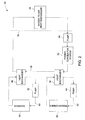
- FIG. 1 is a block diagram representation of an integrated thermal management system 10.
- the thermal management system 10 includes a first device 12 configured to release a first heat loss.
- a second device 14 is configured to release a second heat loss coupled to an integrated cooling system 18 along with the first device 12.
- the system 10 may include a third device 16 releasing a third heat loss.
- the system 10 may include two or more devices releasing respective heat losses.
- the integrated cooling system 18 includes a heat exchanger 20 that separates the first device 12 from the second device 14.
- the first device 12 includes a power converter system
- the second device 14 includes a transformer system
- the third device 16 includes a gearbox or a generator.
- the integrated cooling system 18 includes a first cooling fluid circulated through the first device 12, a second cooling fluid circulated through the second device 14 and a third cooling fluid circulated through the third device 16 via a pump.
- a heat exchanger 20 is coupled to the integrated cooling system 18 to extract heat from the first cooling fluid, the second cooling fluid and the third cooling fluid.
- the heat exchanger 20 may be installed inside or outside a containment such as, but not limited to, the wind turbine tower or nacelle.
- the system 10 may include a common cooling fluid for the first device 12, the second device 14 and the third device 16 as described in FIG. 4 .
- FIG. 2 is a schematic illustration of an integrated thermal management system 30 employed in an application such as, but not limited to, a wind turbine.
- the system 30 includes a power converter system 32 coupled with a pump 34 to provide a first cooling fluid 36.
- the first cooling fluid 36 is water.
- the first cooling fluid 36 is in contact with a heat exchanger 38 coupled to a transformer 40 immersed in a second cooling fluid 42.
- the second cooling fluid 42 is oil.
- a pump 44 circulates the second cooling fluid 42 within the transformer 40.
- the heat exchanger 38 extracts heat from the second cooling fluid 42 to the first cooling fluid 36.
- temperature of the first cooling fluid 36 may be about 60°C and the temperature of the second cooling fluid 40 may be between about 70°C and about 80°C providing a differential in temperature of at least about 10°C.
- the outlet temperature of the cooling fluid 36 at the power converter system 32 will be low enough to be the inlet temperature of the second cooling fluid 42.
- the first cooling fluid 36 is also in contact with a heat exchanger 46 coupled to a third device such as, but not limited to, a gearbox 48 immersed in a third cooling fluid 50.
- the third cooling fluid 50 is oil.
- a pump 52 circulates the third cooling fluid 50 within the gearbox 48.
- the heat exchanger 46 extracts heat from the third cooling fluid 50 to the first cooling fluid 36.
- a heat exchanger 54 is installed outside a wind turbine tower 56 or a nacelle that encloses the thermal management system 30.
- the heat exchanger 54 employs natural convection.
- the heat exchanger 54 employs forced convection using a device such as, but not limited to, a fan.
- the heat exchanger 54 extracts heat from the first cooling fluid 36 into the ambient.
- the integrated thermal management system 30 is installed inside a wind turbine nacelle.
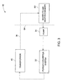
- FIG. 3 is a schematic illustration of another exemplary integrated thermal management system 60 employed in an application such as, but not limited to, a wind turbine.
- the system 60 includes a power converter system 32 as referenced in FIG. 2 coupled with a pump 34 to circulate a first cooling fluid 36 as referenced in FIG. 2 .
- the first cooling fluid 36 is in direct contact with the transformer 40 in FIG. 2 .
- the first cooling fluid 36 is circulated through the power converter system 32 and the transformer 40 to extract heat from both the devices.
- a heat exchanger 62 is installed outside a wind turbine tower 64 or a nacelle that encloses the thermal management system 60 and extracts heat from the first cooling fluid 36 to the ambient.
- the heat exchanger 62 employs natural or free convection.
- the heat exchanger 62 employs forced convection using a device such as, but not limited to, a fan.
- the integrated thermal management system is installed inside a wind turbine nacelle.
- the system 60 may include various electrical components that may be cooled as described above. Further, the electrical components are typically physically placed close to each other and thus facilitate integrated cooling. The system 60 also increases packaging density of the electrical components and enables for a single piece, factory assembled and tested unit. The system 60 reduces number of parts in an assembly and therefore increases reliability of the system.
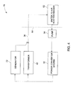
- FIG. 4 is a schematic illustration of another exemplary integrated thermal management system 70 including three devices employed in an application such as, but not limited to, a wind turbine.
- the thermal management system 70 includes an additional third device 72 in contact with the first cooling fluid 36.
- the third device 72 includes a generator.
- cooling of the generator 72 is connected in parallel to the second device 40.
- cooling of the generator 72 may be connected in series to the transformer 40.
- the first cooling fluid 36 extracts heat from the power converter system 32, the transformer 40 and the generator 72.
- a heat exchanger 62 as referenced in FIG. 3 extracts heat from the first cooling fluid 36 to the ambient.
- the heat exchanger 62 is installed outside a wind turbine tower 64 or a nacelle.
- the heat exchanger 62 may be installed inside the wind turbine tower 64.
- FIG. 5 is a flow chart representing exemplary steps in a method 80 for integrating thermal management in a heat generating system.
- the method 80 includes disposing a first device configured to release a first heat loss in step 82.
- a second device is separated from the first device by a heat exchanger in step 84.
- Heat from the first device and the second device is extracted via the heat exchanger in step 86.
- the heat is extracted via forced convective cooling by circulating a cooling fluid through the second device.
- the heat is extracted by circulating a cooling fluid through the first device via a pump.
- the heat extracted is at least about 80 percent of heat generated in the first heat generating device and the second heat device.
- a transformer as a second device with respect to one embodiment can be adapted for use with a third device such as, but not limited to a generator or a gearbox described with respect to another.
- a third device such as, but not limited to a generator or a gearbox described with respect to another.
- the various features described, as well as other known equivalents for each feature can be mixed and matched by one of ordinary skill in this art to construct additional systems and techniques in accordance with principles of this disclosure.
Landscapes
- Engineering & Computer Science (AREA)
- Physics & Mathematics (AREA)
- Thermal Sciences (AREA)
- Microelectronics & Electronic Packaging (AREA)
- General Engineering & Computer Science (AREA)
- Mechanical Engineering (AREA)
- Sustainable Energy (AREA)
- Chemical & Material Sciences (AREA)
- Combustion & Propulsion (AREA)
- Sustainable Development (AREA)
- Life Sciences & Earth Sciences (AREA)
- Wind Motors (AREA)
- Cooling Or The Like Of Electrical Apparatus (AREA)
- Control Of Temperature (AREA)
- Cooling Or The Like Of Semiconductors Or Solid State Devices (AREA)
Applications Claiming Priority (1)
| Application Number | Priority Date | Filing Date | Title |
|---|---|---|---|
| US11/764,495 US20080307817A1 (en) | 2007-06-18 | 2007-06-18 | System for integrated thermal management and method for the same |
Publications (2)
| Publication Number | Publication Date |
|---|---|
| EP2007184A2 true EP2007184A2 (fr) | 2008-12-24 |
| EP2007184A3 EP2007184A3 (fr) | 2011-03-23 |
Family
ID=39802497
Family Applications (1)
| Application Number | Title | Priority Date | Filing Date |
|---|---|---|---|
| EP08157713A Withdrawn EP2007184A3 (fr) | 2007-06-18 | 2008-06-06 | Système de gestion thermique intégrée et procédé correspondant |
Country Status (3)
| Country | Link |
|---|---|
| US (2) | US20080307817A1 (fr) |
| EP (1) | EP2007184A3 (fr) |
| CN (1) | CN101330819A (fr) |
Cited By (13)
| Publication number | Priority date | Publication date | Assignee | Title |
|---|---|---|---|---|
| EP2343960A1 (fr) * | 2009-12-30 | 2011-07-13 | ABB Research Ltd. | Procédé de surveillance et de contrôle des conditions de fonctionnement d'un dispositif qui contient des composants électroniques d'alimentation |
| WO2011042084A3 (fr) * | 2009-10-08 | 2011-11-24 | Robert Bosch Gmbh | Chaîne cinématique et éolienne |
| WO2012028145A1 (fr) * | 2010-08-31 | 2012-03-08 | Vestas Wind Systems A/S | Éolienne comportant un système de transfert thermique |
| CN102518566A (zh) * | 2011-11-30 | 2012-06-27 | 西安久和能源科技有限公司 | 一种用于风力发电机组集中式冷却系统 |
| EP2549846A1 (fr) * | 2011-07-22 | 2013-01-23 | Siemens Aktiengesellschaft | Ajustement des composants d'entraînement d'un véhicule |
| WO2013021487A1 (fr) | 2011-08-10 | 2013-02-14 | 三菱重工業株式会社 | Appareil de production d'énergie éolienne |
| WO2013021670A1 (fr) | 2011-08-10 | 2013-02-14 | 三菱重工業株式会社 | Dispositif de production d'énergie électrique du type à énergie renouvelable |
| WO2013021488A1 (fr) | 2011-08-10 | 2013-02-14 | 三菱重工業株式会社 | Dispositif générateur d'énergie électrique du type à énergie renouvelable |
| EP2578879A1 (fr) * | 2011-10-04 | 2013-04-10 | Siemens Aktiengesellschaft | Agencement de refroidissement pour une éolienne |
| EP2532890A4 (fr) * | 2011-04-05 | 2013-06-19 | Mitsubishi Heavy Ind Ltd | Dispositif generateur d'electricite a energie recuperee |
| WO2014125259A1 (fr) * | 2013-02-13 | 2014-08-21 | Romax Technology Limited | Système de chauffage et de refroidissement de lubrifiant |
| US9514874B2 (en) | 2011-09-02 | 2016-12-06 | Siemens Aktiengesellschaft | Transformer chamber for a wind turbine |
| US12215674B2 (en) * | 2019-11-27 | 2025-02-04 | Siemens Gamesa Renewable Energy A/S | Wind turbine and method for operating the wind turbine |
Families Citing this family (14)
| Publication number | Priority date | Publication date | Assignee | Title |
|---|---|---|---|---|
| KR101021333B1 (ko) * | 2008-09-01 | 2011-03-14 | 두산중공업 주식회사 | 풍력터빈의 나셀 냉각 시스템 |
| WO2011051391A2 (fr) * | 2009-10-28 | 2011-05-05 | Vestas Wind Systems A/S | Système de refroidissement d'éolienne |
| CN101956668A (zh) * | 2010-09-01 | 2011-01-26 | 广东明阳风电产业集团有限公司 | 共用水冷散热方式的风力发电机组 |
| CN102062061A (zh) * | 2010-12-04 | 2011-05-18 | 广州高澜节能技术有限公司 | 风力发电的纯水循环系统的冷却方法及实现其的冷却系统 |
| CN102689586A (zh) * | 2012-05-31 | 2012-09-26 | 北京汽车新能源汽车有限公司 | 一种用于电动汽车的一体化温度控制系统 |
| CN102781204B (zh) * | 2012-08-07 | 2015-10-21 | 广东电网公司 | 用于集装箱式电力电子设备的水冷系统 |
| DE102013221729A1 (de) * | 2012-12-17 | 2014-06-18 | Hyundai Motor Company | Kühlsystem eines fahrzeugs mit motor |
| EP2803855A1 (fr) * | 2013-05-16 | 2014-11-19 | Siemens Aktiengesellschaft | Système de refroidissement à deux circuits de refroidissement pontés, éolienne dotée d'un tel système de refroidissement |
| TWI511260B (zh) * | 2013-07-02 | 2015-12-01 | 緯創資通股份有限公司 | 電氣訊號傳輸裝置及其積體電路 |
| US10104814B2 (en) * | 2014-11-03 | 2018-10-16 | General Electric Company | System and method for cooling electrical components of a power converter |
| TWM542267U (zh) | 2015-08-18 | 2017-05-21 | Molex Llc | 連接器系統 |
| ES1149337Y (es) * | 2015-12-23 | 2016-04-12 | Zheng Ye | Dispositivo de refrigeracion para componentes de aerogeneradores |
| CN109667730B (zh) * | 2017-10-16 | 2020-08-28 | 中车株洲电力机车研究所有限公司 | 一种风力发电机组发电机智能散热方法及装置 |
| CN113775489B (zh) * | 2020-06-09 | 2024-09-20 | 金风科技股份有限公司 | 冷却系统及风力发电机组 |
Family Cites Families (10)
| Publication number | Priority date | Publication date | Assignee | Title |
|---|---|---|---|---|
| DE2138376C3 (de) * | 1971-07-31 | 1978-05-24 | Licentia Patent-Verwaltungs-Gmbh, 6000 Frankfurt | Kühlsystem für in Schränken untergebrachte elektronische Geräte |
| JP3735165B2 (ja) * | 1996-08-23 | 2006-01-18 | 株式会社ダイヘン | 電力変換装置 |
| US6215682B1 (en) * | 1998-09-18 | 2001-04-10 | Mitsubishi Denki Kabushiki Kaisha | Semiconductor power converter and its applied apparatus |
| EP1185790B1 (fr) * | 1999-05-07 | 2004-10-27 | NEG Micon A/S | Eolienne marine a refroidissement par liquide |
| US20020117291A1 (en) * | 2000-05-25 | 2002-08-29 | Kioan Cheon | Computer having cooling apparatus and heat exchanging device of the cooling apparatus |
| US6926070B2 (en) * | 2002-03-22 | 2005-08-09 | Intel Corporation | System and method for providing cooling systems with heat exchangers |
| US6921985B2 (en) * | 2003-01-24 | 2005-07-26 | General Electric Company | Low voltage ride through for wind turbine generators |
| US20050174735A1 (en) * | 2003-08-26 | 2005-08-11 | Nagui Mankaruse | High performance cooling systems |
| JP4928749B2 (ja) * | 2005-06-30 | 2012-05-09 | 株式会社東芝 | 冷却装置 |
| US7168251B1 (en) * | 2005-12-14 | 2007-01-30 | General Electric Company | Wind energy turbine |
-
2007
- 2007-06-18 US US11/764,495 patent/US20080307817A1/en not_active Abandoned
-
2008
- 2008-06-06 EP EP08157713A patent/EP2007184A3/fr not_active Withdrawn
- 2008-06-17 CN CNA2008101289278A patent/CN101330819A/zh active Pending
-
2011
- 2011-11-30 US US13/307,036 patent/US20120068468A1/en not_active Abandoned
Cited By (19)
| Publication number | Priority date | Publication date | Assignee | Title |
|---|---|---|---|---|
| WO2011042084A3 (fr) * | 2009-10-08 | 2011-11-24 | Robert Bosch Gmbh | Chaîne cinématique et éolienne |
| EP2343960A1 (fr) * | 2009-12-30 | 2011-07-13 | ABB Research Ltd. | Procédé de surveillance et de contrôle des conditions de fonctionnement d'un dispositif qui contient des composants électroniques d'alimentation |
| CN103124848A (zh) * | 2010-08-31 | 2013-05-29 | 维斯塔斯风力系统有限公司 | 具有传热系统的风轮机 |
| WO2012028145A1 (fr) * | 2010-08-31 | 2012-03-08 | Vestas Wind Systems A/S | Éolienne comportant un système de transfert thermique |
| US9482205B2 (en) | 2010-08-31 | 2016-11-01 | Vestas Wind Systems A/S | Wind turbine having a heat transfer system |
| CN103124848B (zh) * | 2010-08-31 | 2015-09-16 | 维斯塔斯风力系统有限公司 | 具有传热系统的风轮机 |
| US8684682B2 (en) | 2011-04-05 | 2014-04-01 | Mitsubishi Heavy Industries, Ltd. | Power generating apparatus of renewable energy type |
| EP2532890A4 (fr) * | 2011-04-05 | 2013-06-19 | Mitsubishi Heavy Ind Ltd | Dispositif generateur d'electricite a energie recuperee |
| EP2549846A1 (fr) * | 2011-07-22 | 2013-01-23 | Siemens Aktiengesellschaft | Ajustement des composants d'entraînement d'un véhicule |
| US8632303B2 (en) | 2011-08-10 | 2014-01-21 | Mitsubishi Heavy Industries, Ltd. | Wind turbine generator |
| US8601804B2 (en) | 2011-08-10 | 2013-12-10 | Mitsubishi Heavy Industries, Ltd. | Power generating apparatus of renewable energy type |
| WO2013021488A1 (fr) | 2011-08-10 | 2013-02-14 | 三菱重工業株式会社 | Dispositif générateur d'énergie électrique du type à énergie renouvelable |
| WO2013021670A1 (fr) | 2011-08-10 | 2013-02-14 | 三菱重工業株式会社 | Dispositif de production d'énergie électrique du type à énergie renouvelable |
| WO2013021487A1 (fr) | 2011-08-10 | 2013-02-14 | 三菱重工業株式会社 | Appareil de production d'énergie éolienne |
| US9514874B2 (en) | 2011-09-02 | 2016-12-06 | Siemens Aktiengesellschaft | Transformer chamber for a wind turbine |
| EP2578879A1 (fr) * | 2011-10-04 | 2013-04-10 | Siemens Aktiengesellschaft | Agencement de refroidissement pour une éolienne |
| CN102518566A (zh) * | 2011-11-30 | 2012-06-27 | 西安久和能源科技有限公司 | 一种用于风力发电机组集中式冷却系统 |
| WO2014125259A1 (fr) * | 2013-02-13 | 2014-08-21 | Romax Technology Limited | Système de chauffage et de refroidissement de lubrifiant |
| US12215674B2 (en) * | 2019-11-27 | 2025-02-04 | Siemens Gamesa Renewable Energy A/S | Wind turbine and method for operating the wind turbine |
Also Published As
| Publication number | Publication date |
|---|---|
| CN101330819A (zh) | 2008-12-24 |
| US20120068468A1 (en) | 2012-03-22 |
| EP2007184A3 (fr) | 2011-03-23 |
| US20080307817A1 (en) | 2008-12-18 |
Similar Documents
| Publication | Publication Date | Title |
|---|---|---|
| EP2007184A2 (fr) | Système de gestion thermique intégrée et procédé correspondant | |
| EP2565446B1 (fr) | Système de régulation climatique économe en énergie pour une éolienne en mer | |
| CN101384818B (zh) | 用于风轮机的热管理系统 | |
| DK2527650T3 (en) | System for cooling the nacelle and the heat-generating components of an offshore wind turbine | |
| US8747060B2 (en) | Cooling and climate control system and method for a wind turbine | |
| EP2877997B1 (fr) | Production d'énergie passive pendant une panne de courant de centrale nucléaire | |
| Polikarpova et al. | Direct liquid cooling for an outer‐rotor direct‐drive permanent‐magnet synchronous generator for wind farm applications | |
| JP2008185031A (ja) | プラント統合型冷却システム | |
| CN108644074B (zh) | 风力发电机组机舱散热系统的设计方法 | |
| EP2882961A1 (fr) | Système de refroidissement intégré pour une nacelle d'une turbine éolienne | |
| CN110173402A (zh) | 风力涡轮机冷却布置结构 | |
| KR20130114136A (ko) | 통합 냉각시스템 | |
| EP2752977A2 (fr) | Système de refroidissement d'une machine électrique et méthode d'assemblage de celui-ci | |
| JPH09199152A (ja) | パッケージ型燃料電池発電プラントの換気方法 | |
| KR101906185B1 (ko) | 피동안전계통 및 이를 구비하는 원전 | |
| KR101434443B1 (ko) | 열 교환기를 이용한 공랭식 나셀 냉각장치 | |
| WO2015019664A1 (fr) | Système éolien de génération électrique et procédé pour y introduire/en extraire un transformateur | |
| EP3354119A1 (fr) | Agencement de refroidissement pour refroidir, par exemple, une chambre de soupape de convertisseur | |
| EP3580454B1 (fr) | Système de récupération de chaleur résiduelle d'éolienne | |
| CN115500047A (zh) | 一种散热机柜及变流器 | |
| RU2670428C1 (ru) | Система и способ аварийного расхолаживания ядерного реактора | |
| Berrogaín et al. | World's first enhanced-cooled dry-type transformer for wind off-shore | |
| EP2832992A1 (fr) | Système de refroidissement | |
| EP3517777B1 (fr) | Système de refroidissement passif multisiphon | |
| CN221300054U (zh) | 一种风电机组齿轮箱的两相流体散热系统 |
Legal Events
| Date | Code | Title | Description |
|---|---|---|---|
| PUAI | Public reference made under article 153(3) epc to a published international application that has entered the european phase |
Free format text: ORIGINAL CODE: 0009012 |
|
| AK | Designated contracting states |
Kind code of ref document: A2 Designated state(s): AT BE BG CH CY CZ DE DK EE ES FI FR GB GR HR HU IE IS IT LI LT LU LV MC MT NL NO PL PT RO SE SI SK TR |
|
| AX | Request for extension of the european patent |
Extension state: AL BA MK RS |
|
| PUAL | Search report despatched |
Free format text: ORIGINAL CODE: 0009013 |
|
| AK | Designated contracting states |
Kind code of ref document: A3 Designated state(s): AT BE BG CH CY CZ DE DK EE ES FI FR GB GR HR HU IE IS IT LI LT LU LV MC MT NL NO PL PT RO SE SI SK TR |
|
| AX | Request for extension of the european patent |
Extension state: AL BA MK RS |
|
| RIC1 | Information provided on ipc code assigned before grant |
Ipc: F03D 11/00 20060101ALI20110214BHEP Ipc: H05K 7/20 20060101AFI20081013BHEP |
|
| 17P | Request for examination filed |
Effective date: 20110923 |
|
| AKX | Designation fees paid |
Designated state(s): DE DK ES |
|
| 17Q | First examination report despatched |
Effective date: 20120620 |
|
| STAA | Information on the status of an ep patent application or granted ep patent |
Free format text: STATUS: THE APPLICATION IS DEEMED TO BE WITHDRAWN |
|
| 18D | Application deemed to be withdrawn |
Effective date: 20130103 |