EP2007542B1 - Verfahren zum schweissen eines werkstücks - Google Patents
Verfahren zum schweissen eines werkstücks Download PDFInfo
- Publication number
- EP2007542B1 EP2007542B1 EP07701312A EP07701312A EP2007542B1 EP 2007542 B1 EP2007542 B1 EP 2007542B1 EP 07701312 A EP07701312 A EP 07701312A EP 07701312 A EP07701312 A EP 07701312A EP 2007542 B1 EP2007542 B1 EP 2007542B1
- Authority
- EP
- European Patent Office
- Prior art keywords
- welding
- workpiece
- welding wire
- slag
- wire
- Prior art date
- Legal status (The legal status is an assumption and is not a legal conclusion. Google has not performed a legal analysis and makes no representation as to the accuracy of the status listed.)
- Active
Links
Images

Classifications
-
- B—PERFORMING OPERATIONS; TRANSPORTING
- B23—MACHINE TOOLS; METAL-WORKING NOT OTHERWISE PROVIDED FOR
- B23K—SOLDERING OR UNSOLDERING; WELDING; CLADDING OR PLATING BY SOLDERING OR WELDING; CUTTING BY APPLYING HEAT LOCALLY, e.g. FLAME CUTTING; WORKING BY LASER BEAM
- B23K9/00—Arc welding or cutting
- B23K9/06—Arrangements or circuits for starting the arc, e.g. by generating ignition voltage, or for stabilising the arc
- B23K9/073—Stabilising the arc
- B23K9/0737—Stabilising of the arc position
Definitions
- the invention relates to a method for welding a workpiece according to the preamble of claim 1, comprising a welding torch with a consumable welding wire, which during a welding process, during which an arc between the welding wire and the workpiece burns, by means of a wire feed device substantially in the direction of the workpiece is moved, wherein a process for removing slag at the end of the welding wire is started and carried out.
- the welding wire is pressed against the surface of the workpiece with a certain pressure, thereby removing the slag. Also, this can lead to damage of the welding wire.
- the JP 2000-153358 A describes an ignition method in which the welding torch with the welding wire is moved so far in the direction of the workpiece until the welding wire touches the workpiece. If the contact voltage does not go to zero, this is an indication of the presence of slag, after which the burner is moved back to the starting position and back to the workpiece.
- the object of the invention is to provide a welding method which is not adversely affected by an optionally adhering to the end of the welding wire to be contacted slag and ensures a safe ignition of the arc.
- the object of the invention is achieved in that with the beginning of the slag removal process, the welding current is reduced to a minimum, and the slag removal process of the Welding torch performs no movement and the welding wire with a fast recurring forward / backward movement cyclically a predetermined path length in the direction of the workpiece and a smaller distance away from the workpiece, so that the promotion of the welding wire to the workpiece outweighs of a short circuit monitoring a short circuit between the Welding wire and the workpiece is detected, whereupon the slag removal process is terminated.
- the welding process not interrupted due to a slag adhering to the end of the welding wire to be contacted, which prevents ignition of the arc.
- the slag removal process ensures that the arc is safely ignited for the following welding process, essentially without a time delay.
- the slag removal process can be implemented relatively easily in a suitable welding apparatus, since a short-circuit monitoring known per se can be used to detect the short circuit.
- the measure of reducing the welding current to a minimum at the beginning of the slag removal process prevents the arc from being ignited during this time, while detecting a short circuit.
- the slag removal process may be performed at a time interval at the beginning of an ignition process, at a time interval during an ignition process, or at a time interval before an ignition process.
- the arc is preferably ignited by a so-called SPI (spatter free ignition) ignition method, in which the welding wire is subjected to a small welding current and continuously moves in the direction of the workpiece until it contacts the workpiece is, after the occurrence of a short circuit, the wire conveying direction is reversed and the welding wire is continuously moved away from the workpiece, so that when lifting the welding wire, the arc is ignited.
- the welding wire is moved back to a predefined distance to the workpiece. So before the SFI ignition process, the slag removal process is carried out, with the removal of the slag takes place automatically until the detection of the short circuit.
- the ignition process of the arc which is adapted to the respective welding process, is not adversely affected by the slag removal process.
- the welding wire is substantially conveyed toward the workpiece, thereby increasing the impact force of the welding wire on the workpiece, thus accelerating the removal of the slag.
- the motor current of the wire feeder is monitored and at least the first contact of the welding wire with the workpiece is detected. As a result, it can be prevented that the workpiece is deformed by the conveying force of the welding wire, even if no short circuit has yet been detected by the short circuit monitoring, and thus the slag removal process has not yet been completed.
- the touch of the welding wire is detected by exceeding a predetermined limit value of the motor current over a defined period of time.
- the cyclic, fast returning forward / backward movement of the welding wire for the purpose of removing the slag is preferably carried out at an adjustable frequency between 50 Hz and 150 Hz. This relatively high frequency ensures that the welding process is not significantly prolonged by the duration of the slag removal process.
- the cyclical, fast-forward / backward movement of the welding wire for the purpose of removing the slag is carried out at a frequency which corresponds to the frequency of movement of the welding wire during the set welding process.
- the welding current is increased to a value required for the subsequent ignition process, thus enabling the arc to be ignited immediately after the end of the slag removal process.
- the set time preferably starts when the welding wire touches the workpiece for the first time without a Short circuit was detected.
- Fig. 1 is a welding machine 1 or a welding system for a variety of processes or procedures, such as MIG / MAG welding or TIG / TIG welding or electrode welding process, double wire / tandem welding process, plasma or soldering, etc., shown.
- the welding device 1 comprises a current source 2 with a power part 3, a control device 4 and a switching element 5 assigned to the power part 3 or the control device 4.
- the switching element 5 or the control device 4 is connected to a control valve 6 which is located in a supply line 7 for a shielding gas 8, such as CO 2 , helium or argon and the like., Between a gas storage 9 and a welding torch 10 and a burner is arranged.
- a wire feed device 11 which is customary for MIG / MAG welding, can be actuated via the control device 4, wherein a filler material or a welding wire 13 is supplied from a wire roll 14 into the region of the welding torch 10 via a supply line 12.
- the wire feeder 11 can also be integrated in the welding device 1, in particular in the base housing, and not, as in Fig. 1 represented, be designed as an accessory.
- the wire feeder 11 may supply the welding wire 13 outside the welding torch 10 to the processing station, for which purpose a non-consumable electrode is preferably arranged in the welding torch 10, as is usual in TIG / TIG welding.
- the current for establishing an arc 15, between the non-consumable electrode or the welding wire 13 and a workpiece 16 is supplied via a welding line 17 from the power section 3 of the power source 2 to the welding torch 10, in particular the electrode, wherein the workpieces 16 to be welded via a Further welding line 18 are also connected to the welding device 1, in particular to the power source 2, and thus can be constructed via the arc 15 and the plasma jet formed for a process, a circuit.
- the welding torch 10 can be connected via a cooling circuit 20 to a liquid container, in particular a water tank 21, whereby during commissioning of the welding torch 10 the cooling circuit 19, in particular a liquid arranged in the water tank 21 used liquid pump is started, and thus a cooling of the welding torch 10 can be effected.
- the welding device 1 further has an input and / or output device 22, via which the most varied welding parameters, operating modes or welding programs of the welding device 1 can be set or called up.
- the welding parameters, operating modes or welding programs set via the input and / or output device 22 are forwarded to the control device 4 and from this the individual components of the welding device 1 are subsequently controlled or corresponding setpoint values are input for the control or regulation.
- the welding torch 10 is connected via a hose package 23 to the welding device 1.
- the individual lines from the welding device 1 to the welding torch 10 are arranged.
- the Hose package 23 is connected via a coupling device 24 with the welding torch 10, whereas the individual lines are connected in the hose package 23 with the individual contacts of the welding device 1 via connection sockets or connectors. So that a corresponding strain relief of the hose assembly 23 is ensured, the hose package 23 is connected via a strain relief device 25 with a housing 26, in particular with the base housing of the welding device 1.
- the coupling device 24 can be used for the connection to the welding device 1.
- the welding torch 10 For the different welding methods or welding devices 1, such as TIG devices or MIG / MAG devices or plasma devices, not all previously named components must be used or used. For example, it is possible to carry out the welding torch 10 as an air-cooled welding torch 10.
- a welding process for example a cold metal transfer welding process, hereinafter referred to as CMT (cold metal transfer) process
- CMT cold metal transfer
- a welding process is always started with an ignition of the arc 15, wherein the ignition can be effected for example by a contact ignition or a high-frequency ignition.
- the ignition method for igniting the arc 15 takes place via the lift-arc principle known from the prior art or with the spatter-free ignition (SFI) ignition process.
- SFI spatter-free ignition
- the welding wire 13 is continuously conveyed with a small welding current to the contact with the workpiece 16, whereupon after the occurrence of a short circuit, the wire conveying direction is reversed and the welding wire 13 is moved away from the workpiece 16 continuously, so that when lifting the welding wire 13 of the arc 15 is ignited and optionally the welding wire 13 is conveyed back to a predefined distance to the workpiece 16. This results in the formation of the arc 15, whereby now the actual welding process can be started.
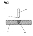
- the welding wire 13 is moved back from a molten bath 43, with a part of the slag 42 located on the surface of the molten bath 43 adhering to the end of the welding wire 13.
- slag 42 may form at the end of the welding wire 13 when, at the end of the welding process, the liquid end of the welding wire 13 solidifies. This often happens when welding steel or steel alloys.
- the slag 42 prevents or impedes the ignition of the arc 15 at the start of the welding process, since no current flow from the welding wire 13 to the workpiece 16 is achieved.
- Another possibility would be to change the angle of incidence of the welding wire 13 to the workpiece 16, whereby possibly the conductive welding wire 13 contacted with the workpiece 16 at the edge zone of the slag 42, a short circuit is detected and by reversing the conveying direction of the welding wire 13 of the arc 15 is ignited.
- the slag 42 at the end of the welding wire 13 is removed by a corresponding movement of the welding wire 13.
- the welding wire 13 is cyclically at high speed back a certain distance before and a smaller distance than forward again. This results in repeated, jerky contact with the slag 42, contacting end of the welding wire 13 with the workpiece 16, whereby the slag 42 is released from the end of the welding wire 13 by the mechanical force upon impact of the welding wire 13 on the workpiece 16.
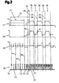
- Fig. 3 is the inventive method for removing the slag 42 from the end of the welding wire 13 during a CMT welding process, with reference to the diagrams 27 to 30, the timing of the welding voltage U, the welding current I, the wire feed speed, and the movements or the end positions of the welding wire 13 relative to the workpiece 16, shown schematically.
- a consumable electrode or a welding wire 13 is used.
- the melting of the workpiece 16 and the welding wire 13 via the ionized plasma column or the arc 15, which takes place between the welding wire 13 and the electrical opposite pole built on the workpiece 16, that is ignited is.
- the ignition phase 31 is started in such a way, for example, by the user pressing a button on the welding torch 10 or doing so automatically.
- the slag removal process takes place in a time interval 47 of the ignition process at the beginning of the ignition phase 31.
- the welding wire 13 is not continuously conveyed to the workpiece 16 with the slag removal process, but instead with a certain frequency, ie moved to the workpiece 16, and back again, ie away from the workpiece 16.
- the welding wire 13 is in this case at high speed back a certain distance before and a smaller distance back than forward again, so that the promotion of the welding wire 13 to the workpiece 16 outweighs.
- the frequency with which the forward / backward movement of the welding wire 13 is performed is preferably between 50 Hz and 150 Hz.
- the frequency defines the duration for the slag removal process. Therefore, especially higher frequencies are important, as this significantly shortens the duration.
- the welding wire 13 is promoted with a rapid recurring forward / backward movement, for example, with a set frequency of 75 Hz, until it touches the workpiece 16.
- the slag 42 adhering to the welding wire 13 contacts the workpiece 16, as can be seen at the time 44. Because of the electrically non-conductive slag 42, no short circuit is detected by the control device 4 or the short circuit monitoring at this time 44, and the welding wire 13 accordingly the set frequency of 75 Hz continues to return back and forth again. As a result, the welding wire 13, which is conveyed with a corresponding conveying force, repeats recurrently with a certain impact force on the workpiece 16. Finally, the slag 42 is released from the end of the welding wire 13 to be contacted, as shown at time 45, and the controller 4 may detect a short circuit, as illustrated at time 46, and terminate the slag removal process.
- a current transfer from the welding wire 13 to the workpiece 16, whereby the ignition of the arc 15 is initiated for the subsequent welding process or the ignition process is continued.
- the continuation of the ignition process for example, the movement of the welding torch 10 or the workpiece 16 in automated welding process is started and performed the welding.
- the welding torch 10 or the workpiece 16 does not move, so that the planned starting point for the welding is maintained.
- the rapidly recurring forward / backward movement of the welding wire 13 is terminated when, with the first contact of the welding wire 13 with the workpiece 16, a short circuit is detected, ie no slag 42 adheres to the end of the welding wire 13 to be contacted. In this case, therefore, no slag removal process takes place, only the recurrent forward / backward movement of the welding wire 13 at the beginning of the ignition process, which initiates the slag removal process.
- the slag 42 prevents a short circuit between the workpiece 16 and the welding wire 13.
- the conveyance of the welding wire 13 is changed in such a way that that in the rapid recurrent forward / backward movement substantially in the forward movement of the welding wire 13 is moved as far as it was moved in the backward movement.
- the slag 42 is removed at the end of the welding wire 13 to be contacted and the risk of deformation of the workpiece 16 or of the welding wire 13 due to the recurrent impact of the welding wire 13 on the workpiece 16 is substantially reduced.
- the slag removal process is terminated with the detection of a short circuit and the ignition process can be continued.
- a method for removing the slag 42 is possible in which the welding wire 13 is continuously conveyed to the first contact with the workpiece 16 before. If the control device 4 does not short-circuit after a predetermined time, or the motor current rises above a predetermined value for a certain time, i.e., slag 42 is at the end of the welding wire 13 to be contacted, the ignition process is interrupted and the slag removal process is initiated. Here, therefore, the slag removal process in the time interval 47 during the ignition (not shown), which in turn was initiated by pressing a button.
- the slag removal process can of course be used for all known ignition methods, such as high-frequency ignition.
- the slag removing process in the high-frequency ignition is performed such that the slag removing process is performed before the RF ignition (not shown).
- the welding wire 13 is positioned accordingly and the ignition process is started.
- the arc 15 is ignited with a high-frequency pulse without contact.
- the welding current I is preferably lowered to a low value, for example below 10 A.
- a low value for example below 10 A.
- the slag removal process may also be limited in time, so that the slag removal process does not take up unnecessarily much time if the slag 42 can not be released by the repetitive forward / backward movement or by the contact with the workpiece 16.
- the time is started as soon as the slag 42 adhering to the end of the welding wire 13 to be contacted touches the workpiece 16 for the first time. This is detected according to the motor current monitoring already described.
- the slag 42 adhering to the end of the welding wire 13 to be contacted can be removed, but also an optionally adhering to the workpiece 16 slag 42.
- the ignition of the arc 15 is also prevented, and accordingly with one of the previously described variants of the slag removal process, the slag 42 is removed from the workpiece 16.
- the slag 42 is removed at the same time at the end of the welding wire 13 to be contacted and on the workpiece 16.
- the current is limited during the ignition phase 31 in one or more stage (s) such that melting of the welding wire 13 can not take place.
- a first short stabilization phase 34 with increased energy input (as shown by dashed lines) over a defined period of time and then built up by cyclically recurring welding process phases welding process can be performed before the actual welding process.
- This has the advantage that a stabilization of the arc 15 and / or a heating of the workpiece 16 or molten bath is created by this short stabilization phase 34 with high energy input.
- the welding wire 13 is heated by the ignition process, and the subsequent welding process may start with preheated welding wire 13, thereby significantly improving the welding quality.
- the welding wire 13 is conveyed in the process phase referred to as the arc phase 36 to the contact with the workpiece 16 before.
- the arc phase 36 the welding wire 13 is melted, so that a drop 37 is formed at the welding wire end.
- the welding current and / or the welding voltage in the arc phase 36 is regulated in such a way that no droplet detachment takes place and at the time 38 a short circuit occurs, which initiates the short-circuit phase 39.
- the wire feeding is reversed, so that the welding wire 13 until the short-circuiting, i. the formation of the arc 15, and / or the defined distance 33 and / or a defined period of time from the workpiece 16 is conveyed back.
- the arc phase 36 enters again, whereupon the direction of movement of the welding wire 13 at a top dead center 32 is again reversed and the welding wire 13 is moved in the direction of the workpiece 16.
- the welding wire 13 experiences an oscillating movement with a specific movement frequency, which corresponds to the number of short circuits per second.
- the movement frequency is 75 Hz, resulting in 75 shorts per second.
- the wire feed device 11 is substantially controlled so that a negative signal or a backward promotion of the welding wire 13 in the short-circuit phase 39 takes place, and then an arc 15 is established, and a positive signal or a forward conveying of the welding wire 13 in the direction of the workpiece 16 takes place in the arc phase 36, in which the heating or melting of the welding wire 13 takes place for droplet formation.
- the control of the direction of movement of the welding wire 13, however, does not necessarily correlate with the occurrence of the arc phase 36 or the short-circuit phase 39, since the arc phase 36 by a targeted energy input via the regulation of the current level in the welding circuit, for example, already during the backward movement of the welding wire 13 can. That is, even with an existing arc 15, the welding wire 13 can continue to be conveyed away from the workpiece 16 up to a defined time or distance.
- the droplet detachment takes place in such a way that, after reaching the dead center 32, a forward movement of the welding wire 13 takes place until the filler material touches the workpiece 16, in particular a molten bath. Due to the surface tension of the drop 37 on the welding wire 13 and in the molten bath or other known physical effects acting this is solved by the welding wire 13. By the backward movement of the welding wire 13, the re-ignition of the arc 15 is favored. Of course, an increase, in particular a pulse-like increase of the welding current I in the short-circuiting phase 39, can be carried out in support of the droplet detachment (not shown). For the duration of the CMT process, the arc phase 36 and the short-circuit phase 39 alternate periodically in the embodiment shown.
- the voltage U and the current I are raised to a first level when the time 35 is exceeded.
- this level can be set as the working level, which is kept constant during the entire arc phase 36 and the short-circuit phase 39 or runs according to a welding process profile.
- the welding current I preferably has a first component, the working current 40, and at least one further component, the base current 41, which ensures reliable reignition of the electric arc 15.
- the base current 41 is preferably relatively small compared to the operating current 40, wherein the current strength of the working current 40 can be, for example, 1.5 to 10 times, in particular 4 to 8 times, higher than the current intensity of the base current 41.
- the base current 41 can be, for example, 5 A to 50 A, in particular approximately 10 A to 30 A, whereas the operating current 40 can be, for example, 50 A to 500 A.
- the slag removal process can also be carried out at the end of a weld seam or a finished workpiece 16 made with a corresponding welding process, consisting of several welds.
- the slag 42 is released from the end to be contacted of the welding wire 13, thereby ensuring a safe ignition of the arc 15 at the beginning of the following weld on the workpiece 16.
Landscapes
- Engineering & Computer Science (AREA)
- Physics & Mathematics (AREA)
- Plasma & Fusion (AREA)
- Mechanical Engineering (AREA)
- Arc Welding Control (AREA)
- Lining Or Joining Of Plastics Or The Like (AREA)
- Electrical Discharge Machining, Electrochemical Machining, And Combined Machining (AREA)
- Pressure Welding/Diffusion-Bonding (AREA)
Description
- Die Erfindung betrifft ein Verfahren zum Schweißen eines Werkstücks gemäß dem Oberbegriff des Anspruchs 1, mit einem Schweißbrenner mit einem abschmelzenden Schweißdraht, welcher während eines Schweißprozesses, während dem ein Lichtbogen zwischen dem Schweißdraht und dem Werkstück brennt, mittels eines Drahtvorschubgeräts im Wesentlichen in Richtung des Werkstücks bewegt wird, wobei ein Prozess zur Entfernung von Schlacke am Ende des Schweißdrahtes gestartet und durchgeführt wird.
- Schweißverfahren mit Prozessen zur Entfernung von Schlacke sind aus dem Stand der Technik bereits bekannt. Beispielsweise zeigt die
JP 4143074 A - Beim Verfahren gemäß der
JP 5245637 A - Die
JP 2000-153358 A - Die Aufgabe der Erfindung liegt darin, ein Schweißverfahren zu schaffen, welches von einer am zu kontaktierenden Ende des Schweißdrahtes gegebenenfalls haftender Schlacke nicht beeinträchtigt wird und ein sicheres Zünden des Lichtbogens gewährleistet.
- Die Aufgabe der Erfindung wird dadurch gelöst, dass mit Beginn des Schlacken-Entfernungsprozesses der Schweißstrom auf ein Minimum gesenkt wird, und beim Schlacken-Entfernungsprozess der Schweißbrenner keine Bewegung ausführt und der Schweißdraht mit einer schnellen wiederkehrenden Vor-/Rückwärtsbewegung zyklisch eine vorgegebene Weglänge in Richtung Werkstück und um eine kleinere Wegstrecke wieder vom Werkstück wegbewegt wird, sodass die Förderung des Schweißdrahtes zum Werkstück überwiegt, bis von einer Kurzschlussüberwachung ein Kurzschluss zwischen dem Schweißdraht und dem Werkstück erkannt wird, worauf der Schlacken-Entfernungsprozess beendet wird. Durch das erfindungsgemäße Verfahren muss das Schweißverfahren nicht aufgrund einer an dem zu kontaktierenden Ende des Schweißdrahtes allenfalls anhaftenden Schlacke, welche ein Zünden des Lichtbogens verhindert, unterbrochen werden. Durch den Schlacken-Entfernungsprozess wird gewährleistet, dass im Wesentlichen ohne Zeitverzögerung der Lichtbogen für den folgenden Schweißprozess sicher gezündet wird. Der Schlacken-Entfernungsprozess kann relativ einfach in einem geeigneten Schweißgerät implementiert werden, da zur Erkennung des Kurzschlusses eine an sich bekannte Kurzschlussüberwachung verwendet werden kann. Durch die Maßnahme des Senkens des Schweißstroms auf ein Minimum mit Beginn des Schlacken-Entfernungsprozesses wird ein Zünden des Lichtbogens in dieser Zeit verhindert, während ein Kurzschluss jedoch erkannt wird.
- Der Schlacken-Entfernungsprozess kann in einem Zeitintervall zu Beginn eines Zündverfahrens, in einem Zeitintervall während eines Zündverfahrens, oder auch in einem Zeitintervall vor einem Zündverfahren durchgeführt werden.
- Nach dem Entfernen der Schlacke vom Schweißdraht wird der Lichtbogen vorzugsweise durch ein so genanntes SFI (spatter free ignition)-Zündverfahren gezündet, bei dem der Schweißdraht mit einem geringen Schweißstrom beaufschlagt wird und kontinuierlich in Richtung des Werkstücks bis zur Berührung mit dem Werkstück nach vor bewegt wird, nach Auftreten eines Kurzschlusses die Drahtförderrichtung umgekehrt und der Schweißdraht kontinuierlich vom Werkstück wegbewegt wird, so dass beim Abheben des Schweißdrahtes der Lichtbogen gezündet wird. Gegebenenfalls wird der Schweißdraht auf einen vordefinierten Abstand zum Werkstück zurückbewegt. Vor dem SFI-Zündverfahren wird also der Schlacken-Entfernungsprozess durchgeführt, wobei das Entfernen der Schlacke bis zur Erkennung des Kurzschlusses automatisch erfolgt. Das auf den jeweiligen Schweißprozess abgestimmte Zündverfahren des Lichtbogens wird durch den Schlacken-Entfernungsprozess nicht negativ beeinflusst. Während des Schlacken-Entfernungsprozesses wird der Schweißdraht im Wesentlichen in Richtung Werkstück gefördert, wodurch die Aufschlagkraft des Schweißdrahtes am Werkstück erhöht wird und somit die Entfernung der Schlacke beschleunigt wird.
- Von Vorteil ist auch, wenn der Motorstrom des Drahtvorschubgeräts überwacht wird und zumindest die erste Berührung des Schweißdrahtes mit dem Werkstück erfasst wird. Dadurch kann verhindert werden, dass durch die Förderkraft des Schweißdrahtes das Werkstück deformiert wird, auch wenn von der Kurzschlussüberwachung noch kein Kurzschluss erkannt wurde, und somit der Schlacken-Entfernungsprozess noch nicht beendet wurde.
- In vorteilhafter Weise wird die Berührung des Schweißdrahtes durch Überschreitung eines vorgegebenen Grenzwertes des Motorstroms über eine definierte Zeitdauer erfasst.
- Die zyklische, schnell wiederkehrende Vor-/Rückwärtsbewegung des Schweißdrahtes zum Zweck des Entfernens der Schlacke wird vorzugsweise mit einer einstellbaren Frequenz zwischen 50 Hz und 150 Hz durchgeführt. Durch diese relativ hohe Frequenz wird erreicht, dass der Schweißprozess durch die Dauer des Schlacken-Entfernungsprozesses nicht wesentlich verlängert wird.
- Gemäß einem weiteren Merkmal der Erfindung ist vorgesehen, dass die zyklische, schnell wiederkehrende Vor-/Rückwärtsbewegung des Schweißdrahtes zum Zweck des Entfernens der Schlacke mit einer Frequenz durchgeführt wird, welche der Bewegungsfrequenz des Schweißdrahtes während des eingestellten Schweißprozesses entspricht.
- Von Vorteil ist auch, dass mit Ende des Schlacken-Entfernungsprozesses der Schweißstrom auf einen für das nachfolgende Zündverfahren erforderlichen Wert erhöht wird, wodurch unmittelbar nach der Beendigung des Schlacken-Entfernungsprozesses ein Zünden des Lichtbogens ermöglicht wird.
- Durch die Maßnahmen, dass der Schlacken-Entfernungsprozess nach einer eingestellten Zeit beendet wird, kann ein unnötiger Zeitverlust verhindert werden, wenn sich die Schlacke an dem zu kontaktierenden Ende des Schweißdrahtes durch den Schlacken-Entfernungsprozess nicht löst.
- Dabei startet die eingestellte Zeit vorzugsweise dann, wenn der Schweißdraht das Werkstück zum ersten Mal berührt, ohne dass ein Kurzschluss erkannt wurde.
- Die vorliegende Erfindung wird anhand der beigefügten, schematischen Zeichnungen näher erläutert. Darin zeigen:
- Fig. 1
- eine schematische Darstellung einer Schweißmaschine bzw. eines Schweißgerätes;
- Fig. 2
- das zu kontaktierende Ende eines Schweißdrahtes mit daran anhaftender Schlacke in schematischer Darstellung; und
- Fig. 3
- schematisch die Zeitverläufe der Schweißspannung, des Schweißstromes und ein Bewegungsdiagramm für den Schweiß- draht während eines Beispiels eines Schweißprozesses mit dem erfindungsgemäßen Verfahren.
- Einführend wird festgehalten, dass gleiche Teile des Ausführungsbeispiels mit gleichen Bezugszeichen versehen werden.
- In
Fig. 1 ist ein Schweißgerät 1 bzw. eine Schweißanlage für verschiedenste Prozesse bzw. Verfahren, wie z.B. MIG/MAG-Schweißen bzw. WIG/TIG-Schweißen oder Elektroden-Schweißverfahren, Doppeldraht/Tandem-Schweißverfahren, Plasma- oder Lötverfahren usw., gezeigt. - Das Schweißgerät 1 umfasst eine Stromquelle 2 mit einem Leistungsteil 3, einer Steuervorrichtung 4 und einem dem Leistungsteil 3 bzw. der Steuervorrichtung 4 zugeordneten Umschaltglied 5. Das Umschaltglied 5 bzw. die Steuervorrichtung 4 ist mit einem Steuerventil 6 verbunden, welches in einer Versorgungsleitung 7 für ein Schutzgas 8, wie beispielsweise CO2, Helium oder Argon und dergl., zwischen einem Gasspeicher 9 und einem Schweißbrenner 10 bzw. einem Brenner angeordnet ist.
- Zudem kann über die Steuervorrichtung 4 noch ein Drahtvorschubgerät 11, welches für das MIG/MAG-Schweißen üblich ist, angesteuert werden, wobei über eine Versorgungsleitung 12 ein Zusatzwerkstoff bzw. ein Schweißdraht 13 von einer Drahtrolle 14 in den Bereich des Schweißbrenners 10 zugeführt wird. Selbstverständlich kann das Drahtvorschubgerät 11 auch im Schweißgerät 1, insbesondere im Grundgehäuse, integriert sein und nicht, wie in
Fig. 1 dargestellt, als Zusatzgerät ausgebildet sein. - Es ist auch möglich, dass das Drahtvorschubgerät 11 den Schweißdraht 13 außerhalb des Schweißbrenners 10 an die Prozessstelle zuführt, wobei hierzu im Schweißbrenner 10 bevorzugt eine nicht abschmelzende Elektrode angeordnet ist, wie dies beim WIG/TIG-Schweißen üblich ist.
- Der Strom zum Aufbauen eines Lichtbogens 15, zwischen der nicht abschmelzenden Elektrode oder dem Schweißdraht 13 und einem Werkstück 16 wird über eine Schweißleitung 17 vom Leistungsteil 3 der Stromquelle 2 dem Schweißbrenner 10, insbesondere der Elektrode, zugeführt, wobei die zu verschweißenden Werkstücke 16 über eine weitere Schweißleitung 18 ebenfalls mit dem Schweißgerät 1, insbesondere mit der Stromquelle 2, verbunden sind und somit über den Lichtbogen 15 bzw. den gebildeten Plasmastrahl für einen Prozess ein Stromkreis aufgebaut werden kann.
- Zum Kühlen des Schweißbrenners 10 kann über einen Kühlkreislauf 19 der Schweißbrenner 10 unter Zwischenschaltung eines Strömungswächters 20 mit einem Flüssigkeitsbehälter, insbesondere einem Wasserbehälter 21, verbunden werden, wodurch bei der Inbetriebnahme des Schweißbrenners 10 der Kühlkreislauf 19, insbesondere eine für die im Wasserbehälter 21 angeordnete Flüssigkeit verwendete Flüssigkeitspumpe, gestartet wird und somit eine Kühlung des Schweißbrenners 10 bewirkt werden kann.
- Das Schweißgerät 1 weist weiters eine Ein- und/oder Ausgabevorrichtung 22 auf, über die die unterschiedlichsten Schweißparameter, Betriebsarten oder Schweißprogramme des Schweißgerätes 1 eingestellt bzw. aufgerufen werden können. Dabei werden die über die Ein- und/oder Ausgabevorrichtung 22 eingestellten Schweißparameter, Betriebsarten oder Schweißprogramme an die Steuervorrichtung 4 weitergeleitet und von dieser werden anschließend die einzelnen Komponenten des Schweißgerätes 1 angesteuert bzw. entsprechende Sollwerte für die Regelung oder Steuerung vorgegeben.
- Weiters ist in dem dargestellten Ausführungsbeispiel der Schweißbrenner 10 über ein Schlauchpaket 23 mit dem Schweißgerät 1 verbunden. In dem Schlauchpaket 23 sind die einzelnen Leitungen vom Schweißgerät 1 zum Schweißbrenner 10 angeordnet. Das Schlauchpaket 23 wird über eine Kupplungsvorrichtung 24 mit dem Schweißbrenner 10 verbunden, wogegen die einzelnen Leitungen im Schlauchpaket 23 mit den einzelnen Kontakten des Schweißgerätes 1 über Anschlussbuchsen bzw. Steckverbindungen verbunden sind. Damit eine entsprechende Zugentlastung des Schlauchpaketes 23 gewährleistet ist, ist das Schlauchpaket 23 über eine Zugentlastungsvorrichtung 25 mit einem Gehäuse 26, insbesondere mit dem Grundgehäuse des Schweißgerätes 1, verbunden. Selbstverständlich kann auch die Kupplungsvorrichtung 24 für die Verbindung am Schweißgerät 1 eingesetzt werden.
- Für die unterschiedlichen Schweißverfahren bzw. Schweißgeräte 1, wie beispielsweise WIG-Geräte oder MIG/MAG-Geräte oder Plasmageräte, müssen nicht alle zuvor benannten Komponenten verwendet bzw. eingesetzt werden. Beispielsweise ist es möglich, den Schweißbrenner 10 als luftgekühlten Schweißbrenner 10 auszuführen.
- Mit dem beschriebenen Schweißgerät 1 kann nunmehr ein Schweißprozess, beispielsweise ein Kalt-Metall-Transfer-Schweißprozess, im folgenden CMT(Cold Metal Transfer)-Prozess genannt, durchgeführt werden. Ein Schweißprozess wird stets mit einer Zündung des Lichtbogens 15 gestartet, wobei die Zündung beispielsweise durch eine Kontaktzündung oder eine Hochfrequenzzündung erfolgen kann. Beispielsweise erfolgt das Zündverfahren zum Zünden des Lichtbogens 15 über das aus dem Stand der Technik bekannte Lift-Arc-Prinzip bzw. mit dem SFI(spatter free ignition)-Zündprozess. Dabei wird der Schweißdraht 13 mit einem geringen Schweißstrom bis zur Berührung mit dem Werkstück 16 kontinuierlich nach vor gefördert, worauf nach Auftreten eines Kurzschlusses die Drahtförderrichtung umgekehrt wird und der Schweißdraht 13 vom Werkstück 16 kontinuierlich wegbewegt wird, so dass beim Abheben des Schweißdrahtes 13 der Lichtbogen 15 gezündet wird und gegebenenfalls der Schweißdraht 13 auf einen vordefinierten Abstand zum Werkstück 16 zurückgefördert wird. Dadurch erfolgt die Bildung des Lichtbogens 15, wodurch nunmehr der eigentliche Schweißprozess gestartet werden kann.
- Bei der soeben beschriebenen Kontaktzündung ist es wesentlich, dass der elektrisch leitende Schweißdraht 13 auch tatsächlich mit dem Werkstück 16 kontaktiert. Dies erkennt die Steuervorrichtung 4 anhand einer aus dem Stand der Technik bekannten Kurzschlusserkennung und ändert daraufhin die Förderrichtung des Schweißdrahtes 13.
- Befindet sich jedoch Schlacke 42, welche nicht oder nur schlecht elektrisch leitfähig ist, an dem zu kontaktierenden Ende des Schweißdrahtes 13, wie in
Fig. 2 dargestellt, berührt diese zuerst das Werkstück 16, wodurch keine elektrische Kontaktierung und somit keine Zündung des Lichtbogens 15 erfolgen kann. Bereits eine geringe Menge an Schlacke 42, beispielsweise in Form einer Kugel oder Kappe, an dem zu kontaktierenden Ende des Schweißdrahtes 13 verhindert häufig die elektrische Kontaktierung und somit Zündung. Bekannte Verfahren für ein begünstigtes Zünden des Lichtbogens 15, wie die Bildung eines möglichst geringen Zündquerschnittes des Schweißdrahtes 13 am Ende eines Schweißprozesses, können dieses Problem nicht beseitigen. - Der Grund besteht darin, dass beim Beenden eines Schweißprozesses der Schweißdraht 13 aus einem Schmelzbad 43 zurückbewegt wird, wobei ein Teil der an der Oberfläche des Schmelzbades 43 befindlichen Schlacke 42 am Ende des Schweißdrahtes 13 haften bleibt. Auch kann sich Schlacke 42 am Ende des Schweißdrahtes 13 bilden, wenn am Ende des Schweißprozesses das flüssige Ende des Schweißdrahtes 13 erstarrt. Häufig erfolgt dies beim Schweißen von Stahl bzw. Stahllegierungen. Somit verhindert oder erschwert die Schlacke 42 beim Start des Schweißprozesses das Zünden des Lichtbogens 15, da kein Stromfluss vom Schweißdraht 13 zum Werkstück 16 zustande kommt. Deshalb wird auch kein Kurzschluss durch eine Kurzschlussüberwachung erkannt und der Schweißdraht 13 weiter in Richtung Werkstück 16 befördert, wodurch das Werkstück 16 gegebenenfalls beschädigt oder sogar deformiert werden kann. Dies kann beispielsweise durch die Überwachung des Motorstromes des Drahtvorschubgerätes 11 verhindert werden, indem die Förderung des Schweißdrahtes 13 gestoppt wird, wenn der Motorstrom einen vorgegebenen Grenzwert für eine bestimmte Zeitspanne übersteigt. Dies ist insofern möglich, da die Vorschubkraft und der Motorstrom proportional zueinander sind.
- Damit nun ein Wiederzünden des Lichtbogens 15 erfolgen kann, muss beispielsweise das zu kontaktierende Ende des Schweißdrahtes 13 und damit die anhaftende, elektrisch nicht leitende Schlacke 42 manuell oder automatisiert entfernt oder das Drahtende abgeschnitten werden.
- Eine weitere Möglichkeit wäre auch, den Auftreffwinkel des Schweißdrahtes 13 zum Werkstück 16 zu verändern, wodurch gegebenenfalls der leitende Schweißdraht 13 mit dem Werkstück 16 an der Randzone der Schlacke 42 kontaktiert, ein Kurzschluss erkannt wird und durch die Umkehr der Förderrichtung des Schweißdrahtes 13 der Lichtbogen 15 gezündet wird. Der dafür notwendige Aufwand für die Programmierung des Roboters, welcher den Schweißbrenner 10 führt, ist jedoch sehr hoch.
- Erfindungsgemäß ist nun vorgesehen, dass die Schlacke 42 am Ende des Schweißdrahtes 13 durch eine entsprechende Bewegung des Schweißdrahtes 13 entfernt wird. Dabei wird der Schweißdraht 13 zyklisch mit hoher Geschwindigkeit eine bestimmte Wegstrecke nach vor und eine kleinere Wegstrecke als vorwärts wieder zurückgefördert. Daraus resultiert ein wiederholtes, stoßartiges Berühren des mit Schlacke 42 behafteten, zu kontaktierenden Endes des Schweißdrahtes 13 mit dem Werkstück 16, wodurch die Schlacke 42 vom Ende des Schweißdrahtes 13 durch die mechanische Krafteinwirkung beim Auftreffen des Schweißdrahtes 13 auf dem Werkstück 16 gelöst wird.
- In
Fig. 3 ist das erfindungsgemäße Verfahren zum Entfernen der Schlacke 42 vom Ende des Schweißdrahtes 13 während eines CMT-Schweißprozesses, anhand der Diagramme 27 bis 30, welche den zeitlichen Verlauf der Schweißspannung U, des Schweißstroms I, der Drahtvorschubgeschwindigkeit, und der Bewegungen bzw. Stellungen des Endes des Schweißdrahtes 13 relativ zum Werkstück 16 zeigen, schematisch dargestellt. - Bei dem dargestellten Schweißverfahren zum Steuern und/oder Regeln des Schweißgerätes 1 bzw. der Schweißstromquelle, wird eine abschmelzende Elektrode bzw. ein Schweißdraht 13 eingesetzt. Dabei erfolgt die Aufschmelzung des Werkstücks 16 und des Schweißdrahtes 13 über die ionisierte Plasmasäule bzw. den Lichtbogen 15, der zwischen dem Schweißdraht 13 und dem elektrischen Gegenpol am Werkstück 16 aufgebaut, sprich gezündet, wird. Dies erfolgt in einer Zündphase 31, in welcher das Zündverfahren, beispielsweise die SFI-Zündung, durchgeführt wird. Die Zündphase 31 wird beispielsweise derart gestartet, indem am Schweißbrenner 10 vom Benutzer ein Taster gedrückt wird bzw. dies automatisiert erfolgt.
- Um zu verhindern, dass aufgrund der am Schweißdraht 13 haftenden Schlacke 42 der Lichtbogen 15 gegebenenfalls nicht gezündet wird, erfolgt der erfindungsgemäße Schlacken-Entfernungsprozess in einem Zeitintervall 47 des Zündverfahrens am Beginn der Zündphase 31.
- Dabei wird mit dem Schlacken-Entfernungsprozess der Schweißdraht 13 nicht kontinuierlich zum Werkstück 16 gefördert, sondern mit einer bestimmten Frequenz vor, also zum Werkstück 16 bewegt, und wieder zurück, also vom Werkstück 16 entfernt. Der Schweißdraht 13 wird hierbei mit hoher Geschwindigkeit eine bestimmte Wegstrecke nach vor und eine kleinere Wegstrecke als vorwärts wieder zurückgefördert, so dass die Förderung des Schweißdrahtes 13-zum Werkstück 16 überwiegt. Hierbei liegt die Frequenz, mit welcher die Vor-/Rückwärtsbewegung des Schweißdrahtes 13 durchgeführt wird, bevorzugt zwischen 50 Hz und 150 Hz. Selbstverständlich ist es auch möglich, niedrigere oder höhere Frequenzen für den Schlacken-Entfernungsprozess zu verwenden. Grundsätzlich ist hierbei zu beachten, dass mit der Frequenz die Dauer für den Schlacken-Entfernungsprozess definiert wird. Deshalb sind insbesondere höhere Frequenzen von Bedeutung, da dadurch die Dauer wesentlich verkürzt wird.
- Somit wird also der Schweißdraht 13 mit einer schnellen wiederkehrenden Vor-/Rückwärtsbewegung, beispielsweise mit einer eingestellten Frequenz von 75 Hz, bis zur Berührung mit dem Werkstück 16 gefördert.
- Somit berührt die am Schweißdraht 13 haftende Schlacke 42, wie zum Zeitpunkt 44 ersichtlich, das Werkstück 16. Aufgrund der elektrisch nicht leitenden Schlacke 42 wird zu diesem Zeitpunkt 44 kein Kurzschluss von der Steuervorrichtung 4 bzw. der Kurzschlussüberwachung erkannt, und der Schweißdraht 13 entsprechend der eingestellten Frequenz von 75 Hz weiterhin wiederkehrend zurück und wieder vor bewegt. Daraus resultiert, dass der Schweißdraht 13, welcher mit einer entsprechenden Förderkraft gefördert wird, wiederkehrend mit einer bestimmten Aufschlagkraft am Werkstück 16 auftrifft. Schließlich wird die Schlacke 42 von dem zu kontaktierenden Ende des Schweißdrahtes 13 gelöst, wie zum Zeitpunkt 45 dargestellt, und die Steuervorrichtung 4 kann einen Kurzschluss detektieren, wie zum Zeitpunkt 46 dargestellt, und den Schlacken-Entfernungsprozess beenden.
- Somit erfolgt ein Stromübergang vom Schweißdraht 13 auf das Werkstück 16, wodurch die Zündung des Lichtbogens 15 für den darauf folgenden Schweißprozess eingeleitet wird bzw. das Zündverfahren fortgesetzt wird. Mit dem Fortsetzen des Zündverfahrens wird auch beispielsweise die Bewegung des Schweißbrenners 10 oder des Werkstücks 16 bei automatisierten Schweißverfahren gestartet und die Schweißung durchgeführt. Selbstverständlich führt der Schweißbrenner 10 oder das Werkstück 16 beim Entfernen der Schlacke 42 keine Bewegung aus, so dass der geplante bzw. programmierte Startpunkt für die Schweißung beibehalten wird.
- Die schnell wiederkehrende Vor-/Rückwärtsbewegung des Schweißdrahtes 13 wird beendet, wenn mit der ersten Berührung des Schweißdrahtes 13 mit dem Werkstück 16 ein Kurzschluss erkannt wird, also keine Schlacke 42 an dem zu kontaktierenden Ende des Schweißdrahtes 13 haftet. In diesem Fall findet also kein Schlacken-Entfernungsprozess statt, lediglich die wiederkehrende Vor-/Rückwärtsbewegung des Schweißdrahtes 13 am Beginn des Zündverfahrens, welche den Schlacken-Entfernungsprozess einleitet.
- Im soeben beschriebenen Verfahren zum Entfernen der Schlacke 42 überwiegt die Förderung des Schweißdrahtes 13 zum Werkstück 16. Ebenso ist es auch möglich, dass zwischen den Zeitpunkten 44 und 46 nicht die Förderung des Schweißdrahtes 13 zum Werkstück 16 überwiegt, sondern dass lediglich im Wesentlichen so viel Schweißdraht 13 wieder nach vor gefördert wird, wie zuvor zurückgefördert wurde.
- Dies erfolgt beispielsweise derart, dass die erste Berührung des Schweißdrahtes 13 mit dem Werkstück 16, nachdem der Schweißdraht 13 mit der wiederkehrenden Vor-/Rückwärtsbewegung zum Werkstück 16 gefördert wurde, durch eine Motorstromüberwachung erkannt wird. Hierbei werden entsprechend die Ströme des Motors bzw. der Motoren, welcher bzw. welche den Schweißdraht 13 von der Vorratstrommel 14 bis in den Schweißbrenner 10 bzw. zum Werkstück 16 fördern, überwacht.
- Wird von der Motorstromüberwachung über eine gewisse Zeit bzw. eine definierte Zeitdauer ein zu höher Motorstrom erkannt bzw. gemessen, verhindert die Schlacke 42 einen Kurzschluss zwischen Werkstück 16 und Schweißdraht 13. Zum Entfernen der Schlacke 42 wird nun die Förderung des Schweißdrahtes 13 derart geändert, dass bei der schnellen wiederkehrenden Vor-/Rückwärtsbewegung im Wesentlichen bei der Vorwärtsbewegung der Schweißdraht 13 so weit bewegt wird, wie dieser bei der Rückwärtsbewegung bewegt wurde. Dadurch wird die Schlacke 42 an dem zu kontaktierenden Ende des Schweißdrahtes 13 entfernt sowie die Gefahr einer Deformation des Werkstücks 16 bzw. des Schweißdrahtes 13 aufgrund des wiederkehrenden Auftreffens des Schweißdrahtes 13 auf das Werkstück 16 wesentlich reduziert.
- Somit wird der Schlacken-Entfernungsprozess mit dem Erkennen eines Kurzschlusses beendet und das Zündverfahren kann fortgesetzt werden.
- Selbstverständlich ist auch ein Verfahren zum Entfernen der Schlacke 42 möglich, bei dem der Schweißdraht 13 bis zur ersten Berührung mit dem Werkstück 16 kontinuierlich nach vor gefördert wird. Erkennt die Steuervorrichtung 4 nach einer vorgegebenen Zeit keinen Kurzschluss oder steigt der Motorstrom eine gewisse Zeit über einen vorgegebenen Wert, d.h., dass sich Schlacke 42 an dem zu kontaktierenden Ende des Schweißdrahtes 13 befindet, wird das Zündverfahren unterbrochen und der Schlacken-Entfernungsprozess eingeleitet. Hierbei erfolgt also der Schlacken-Entfernungsprozess im Zeitintervall 47 während des Zündverfahrens (nicht dargestellt), welches wiederum mit Betätigen eines Tasters eingeleitet wurde.
- Die schnell wiederkehrende Vor-/Rückwärtsbewegung des Schweißdrahtes 13 wird beispielsweise mit einer eingestellten Frequenz von 75 Hz durchgeführt. Erkennt die Steuervorrichtung 4 bzw. die Kurzschlussüberwachung nach einigen Berührungen des Schweißdrahtes 13 mit dem Werkstück 16 einen Kurzschluss, wurde die Schlacke 42 erfolgreich gelöst und der Schweißprozess wird eingeleitet bzw. das Zündverfahren fortgesetzt.
- Der Schlacken-Entfernungsprozess kann selbstverständlich für alle bekannten Zündverfahren, wie beispielsweise auch die Hochfrequenzzündung, eingesetzt werden.
- Beispielsweise erfolgt der Schlacken-Entfernungsprozess bei der Hochfrequenzzündung derart, dass vor der HF-Zündung der Schlacken-Entfernungsprozess durchgeführt wird (nicht dargestellt). Ist der Schlacken-Entfernungsprozess beendet, wird der Schweißdraht 13 entsprechend positioniert und das Zündverfahren gestartet. Gemäß der HF-Zündung wird der Lichtbogen 15 mit einem Hochfrequenzimpuls berührungslos gezündet.
- Damit während des Schlacken-Entfernungsprozesses ein Zünden des Lichtbogens 15 nahezu gänzlich ausgeschlossen werden kann, wird der Schweißstrom I bevorzugt auf einen niedrigen Wert, beispielsweise unter 10 A, gesenkt. Somit wird auch zum Zeitpunkt 45, an welchem die Schlacke 42 entfernt wird, gewährleistet, dass der Schweißdraht 13 nicht am Werkstück 16 festbrennt oder versehentlich bei der folgenden Rückwärtsbewegung des Schweißdrahtes 13 ein Lichtbogen 15 gezündet wird. Nach Beendigung des Schlacken-Entfernungsprozesses wird der Schweißstrom I wieder auf den ursprünglich eingestellten Schweißstrom I erhöht, so dass das folgende Zündverfahren bzw. der folgende Schweißprozess uneingeschränkt durchgeführt werden kann.
- Der Schlacken-Entfernungsprozess kann beispielsweise auch zeitlich begrenzt sein, so dass der Schlacken-Entfernungsprozess nicht unnötig viel Zeit in Anspruch nimmt, wenn die Schlacke 42 durch die wiederkehrende Vor-/Rückwärtsbewegung bzw. durch die Berührungen mit dem Werkstück 16 nicht gelöst werden kann. Hierbei wird die Zeit gestartet, sobald die auf dem zu kontaktierenden Ende des Schweißdrahtes 13 haftende Schlacke 42 zum ersten Mal das Werkstück 16 berührt. Dies wird gemäß der bereits beschriebenen Motorstromüberwachung erkannt.
- Selbstverständlich kann mit dem erfindungsgemäßen Schlacken-Entfernungsprozess nicht nur die am zu kontaktierenden Ende des Schweißdrahtes 13 haftende Schlacke 42 entfernt werden, sondern auch eine gegebenenfalls am Werkstück 16 haftende Schlacke 42. In diesem Fall wird ebenso das Zünden des Lichtbogens 15 verhindert, wobei dementsprechend mit einer der zuvor beschriebenen Varianten des Schlacken-Entfernungsprozesses die Schlacke 42 vom Werkstück 16 entfernt wird. Hierbei kann es natürlich auch vorkommen, dass die Schlacke 42 gleichzeitig an dem zu kontaktierenden Ende des Schweißdrahtes 13 sowie am Werkstück 16 entfernt wird.
- Nachdem also gegebenenfalls der Schlacken-Entfernungsprozess während des Zündverfahrens durchgeführt wurde und das Zündverfahren beendet wurde, folgt der eigentliche Schweißprozess.
- Nach dem Zünden des Lichtbogens 15, beispielsweise mit dem SFI-Zündprozess, erfolgt die Rückförderung des Schweißdrahtes 13 vom Werkstück 16 bis an einen oberen Totpunkt 32, bis ein definierter Abstand 33 erreicht ist und/oder eine definierte Zeitdauer abgelaufen ist. Der Strom ist während der Zündphase 31 in einer oder mehreren Stufe(n) derart begrenzt, dass ein Schmelzen des Schweißdrahtes 13 nicht erfolgen kann.
- Nach dem Zünden des Lichtbogens 15 bzw. Erreichen des Abstandes 33 kann vor dem eigentlichen Schweißprozess eine erste kurze Stabilisierungsphase 34 mit erhöhter Energieeinbringung (wie mit strichlierten Linien dargestellt) über eine definierte Zeitdauer und anschließend der durch zyklisch wiederkehrende Schweißprozessphasen aufgebaute Schweißprozess durchgeführt werden. Dies hat den Vorteil, dass durch diese kurze Stabilisierungsphase 34 mit hoher Energieeinbringung eine Stabilisierung des Lichtbogens 15 und/oder eine Erwärmung des Werkstücks 16 bzw. Schmelzbades geschaffen wird. Des Weiteren wird der Schweißdraht 13 durch den Zündprozess erwärmt und der nachfolgende Schweißprozess kann mit vorerwärmtem Schweißdraht 13 beginnen, wodurch die Schweißqualität wesentlich verbessert wird.
- Nach der Zündphase 31 bzw. der Stabilisierungsphase 34 erfolgt zum Zeitpunkt 35 der eigentliche Schweißprozess, wobei beispielsweise ein Kalt-Metall-Transfer(Cold Metal Transfer-CMT)-Schweißprozess durchgeführt wird, welcher nun kurz beschrieben wird.
- Beim CMT-Prozess wird der Schweißdraht 13 in der als Lichtbogenphase 36 bezeichneten Prozessphase bis zur Berührung mit dem Werkstück 16 nach vor gefördert. In der Lichtbogenphase 36 erfolgt ein Anschmelzen des Schweißdrahts 13, so dass am Schweißdrahtende ein Tropfen 37 entsteht. Der Schweißstrom und/oder die Schweißspannung in der Lichtbogenphase 36 wird derart geregelt, dass keine Tropfenablösung erfolgt und zum Zeitpunkt 38 ein Kurzschluss eintritt, welcher die Kurzschlussphase 39 einleitet. In der Kurzschlussphase 39 wird die Drahtförderung umgekehrt, so dass der Schweißdraht 13 bis zum Aufbrechen des Kurzschlusses, d.h. der Bildung des Lichtbogens 15, und/oder dem definierten Abstand 33 und/oder eine definierte Zeitdauer vom Werkstück 16 zurückgefördert wird. Zum Zeitpunkt 35 tritt erneut die Lichtbogenphase 36 ein, worauf die Bewegungsrichtung des Schweißdrahts 13 an einem oberen Totpunkt 32 erneut umgekehrt wird und der Schweißdraht 13 in Richtung des Werkstücks 16 bewegt wird.
- Der Schweißdraht 13 erfährt also während des Schweißprozesses eine oszillierende Bewegung mit einer bestimmten Bewegungsfrequenz, welche der Anzahl der Kurzschlüsse pro Sekunde entspricht. Beispielsweise beträgt die Bewegungsfrequenz 75 Hz, woraus sich also 75 Kurzschlüsse pro Sekunde ergeben. Dabei wird das Drahtvorschubgerät 11 im Wesentlichen so gesteuert, dass ein negatives Signal bzw. eine Rückwärtsförderung des Schweißdrahtes 13 in der Kurzschlussphase 39 erfolgt, und anschließend ein Lichtbogen 15 aufgebaut wird, und ein positives Signal bzw. eine Vorwärtsförderung des Schweißdrahtes 13 in Richtung des Werkstücks 16 in der Lichtbogenphase 36 erfolgt, in der das Erhitzen bzw. Anschmelzen des Schweißdrahtes 13 zur Tropfenbildung erfolgt. Die Steuerung der Bewegungsrichtung des Schweißdrahtes 13 muss jedoch nicht unbedingt mit dem Auftreten der Lichtbogenphase 36 bzw. der Kurzschlussphase 39 korrelieren, da die Lichtbogenphase 36 durch eine gezielte Energieeinbringung über die Regelung des Stromniveaus im Schweißkreis beispielsweise bereits während der Rückwärtsbewegung des Schweißdrahtes 13 erfolgen kann. D.h. es kann auch bei bereits vorhandenem Lichtbogen 15 der Schweißdraht 13 weiterhin bis zu einem definierten Zeitpunkt bzw. Abstand vom Werkstück 16 weggefördert werden.
- Die Tropfenablöse erfolgt derart, dass nach Erreichen des Totpunktes 32 eine Vorwärtsbewegung des Schweißdrahtes 13 bis zur Berührung des Zusatzwerkstoffes mit dem Werkstück 16, insbesondere einem Schmelzbad, erfolgt. Durch die Oberflächenspannung des Tropfens 37 am Schweißdraht 13 und im Schmelzbad bzw. weiterer bekannter wirkender physikalischer Effekte wird dieser vom Schweißdraht 13 gelöst. Durch die Rückwärtsbewegung des Schweißdrahtes 13 wird das Wiederzünden des Lichtbogens 15 begünstigt. Zur Unterstützung der Tropfenablöse kann natürlich eine Erhöhung, insbesondere eine impulsartige Erhöhung des Schweißstromes I in der Kurzschlussphase 39 durchgeführt werden (nicht dargestellt). Für die Dauer des CMT-Prozesses wechseln sich die Lichtbogenphase 36 und die Kurzschlussphase 39 im gezeigten Ausführungsbeispiel periodisch ab.
- Aus
Fig. 3 ist auch ersichtlich, dass die Spannung U bzw. der Strom I mit Überschreiten des Zeitpunkts 35 auf ein erstes Niveau angehoben werden. Gegebenenfalls kann dieses Niveau als Arbeitsniveau festgelegt werden, das während der gesamten Lichtbogenphase 36 und der Kurzschlussphase 39 konstant gehalten wird bzw. nach einem Schweißprozessprofil verläuft. Wie aus dem Diagramm 28 hervorgeht, weist bevorzugt der Schweißstrom I einen ersten Anteil, den Arbeitsstrom 40, und zumindest einen weiteren Anteil, den Grundstrom 41, welcher ein sicheres Wiederzünden des Lichtbogens 15 gewährleistet, auf. - Der Grundstrom 41 ist gegenüber dem Arbeitsstrom 40 bevorzugt verhältnismäßig klein, wobei die Stromstärke des Arbeitsstroms 40 beispielsweise um das 1,5 bis 10-fache, insbesondere das 4 bis 8-fache, höher als die Stromstärke des Grundstroms 41 sein kann. Der Grundstrom 41 kann beispielsweise 5 A bis 50 A, insbesondere ca. 10 A bis 30 A, betragen, wogegen der Arbeitsstrom 40 beispielsweise 50 A bis 500 A betragen kann.
- Auf weitere, verfahrenstechnische Details des CMT-Prozesses wird an dieser Stelle nicht eingegangen, da dieser für Schweißprozesse mit konstanter und wechselnder Polarität des Schweißstromes am Schweißdraht 13 bzw. dem Werkstück 16 bereits aus dem Stand der Technik bekannt ist.
- Selbstverständlich kann der Schlacken-Entfernungsprozess auch am Ende einer mit einem entsprechenden Schweißprozess gefertigten Schweißnaht oder eines gefertigten Werkstücks 16, bestehend aus mehreren Schweißnähten, durchgeführt werden. Somit wird die Schlacke 42 vom zu kontaktierenden Ende des Schweißdrahtes 13 gelöst und dadurch ein sicheres Zünden des Lichtbogens 15 am Beginn der folgenden Schweißnaht am Werkstück 16 gewährleistet.
Claims (12)
- Verfahren zum Schweißen eines Werkstücks (16) mit einem Schweißbrenner (10) mit einem abschmelzenden Schweißdraht (13), welcher während eines Schweißprozesses, während dem ein Lichtbogen (15) zwischen dem Schweißdraht (13) und dem Werkstück (16) brennt, mittels eines Drahtvorschubgeräts (11) im Wesentlichen in Richtung des Werkstücks (16) bewegt wird, wobei ein Prozess zur Entfernung von Schlacke (42) am Ende des Schweißdrahtes (13) gestartet und durchgeführt wird, dadurch gekennzeichnet, dass mit Beginn des Schlacken-Entfernungsprozesses der Schweißstrom (I) auf ein Minimum gesenkt wird, und beim Schlacken-Entfernungsprozess der Schweißbrenner (10) keine Bewegung ausführt und der Schweißdraht (13) mit einer schnellen wiederkehrenden Vor-/Rückwärtsbewegung zyklisch eine vorgegebene Weglänge in Richtung Werkstück (16) und um eine kleinere Wegstrecke wieder vom Werkstück (16) wegbewegt wird, sodass die Förderung des Schweißdrahtes (13) zum Werkstück (16) überwiegt, bis von einer Kurzschlussüberwachung ein Kurzschluss zwischen dem Schweißdraht (13) und dem Werkstück (16) erkannt wird, worauf der Schlacken-Entfernungsprozess beendet wird.
- Verfahren nach Anspruch 1, dadurch gekennzeichnet, dass der Schlacken-Entfernungsprozess in einem Zeitintervall (47) zu Beginn eines Verfahrens zum Zünden des Lichtbogens (15) durchgeführt wird.
- Verfahren nach Anspruch 1, dadurch gekennzeichnet, dass der Schlacken-Entfernungsprozess in einem Zeitintervall (47) während eines Verfahrens zum Zünden des Lichtbogens (15) durchgeführt wird.
- Verfahren nach Anspruch 1, dadurch gekennzeichnet, dass der Schlacken-Entfernungsprozess in einem Zeitintervall (47) vor einem Verfahren zum Zünden des Lichtbogens (15) durchgeführt wird.
- Verfahren nach einem der Ansprüche 1 bis 4, dadurch gekennzeichnet, dass nach dem Entfernen der Schlacke (42) der Lichtbogen (15) durch ein Zündverfahren gezündet wird, bei dem der Schweißdraht (13) mit einem geringen Schweißstrom (I) beaufschlagt wird und kontinuierlich in Richtung des Werkstücks (16) bis zur Berührung mit dem Werkstück (16) nach vor bewegt wird, nach Auftreten eines Kurzschlusses die Drahtförderrichtung umgekehrt und der Schweißdraht (13) kontinuierlich vom Werkstück (16) wegbewegt wird, so dass beim Abheben des Schweißdrahtes (13) der Lichtbogen (15) gezündet wird.
- Verfahren nach einem der Ansprüche 1 bis 5, dadurch gekennzeichnet, dass der Motorstrom des Drahtvorschubgeräts (11) überwacht wird und zumindest die erste Berührung des Schweißdrahtes (13) mit dem Werkstück (16) erfasst wird.
- Verfahren nach Anspruch 6, dadurch gekennzeichnet, dass die Berührung des Schweißdrahtes (13) durch Überschreitung eines vorgegebenen Grenzwertes des Motorstromes über eine definierte Zeitdauer erfasst wird.
- Verfahren nach einem der Ansprüche 1 bis 7, dadurch gekennzeichnet, dass die zyklische, schnell wiederkehrende Vor-/Rückwärtsbewegung des Schweißdrahtes (13) zum Zweck des Entfernens der Schlacke (42) mit einer einstellbaren Frequenz zwischen 50 Hz und 150 Hz durchgeführt wird.
- Verfahren nach Anspruch 8, dadurch gekennzeichnet, dass die zyklische, schnell wiederkehrende Vor-/Rückwärtsbewegung des Schweißdrahtes (13) zum Zweck des Entfernens der Schlacke (42) mit einer Frequenz durchgeführt wird, welche der Bewegungsfrequenz des Schweißdrahtes (13) während des eingestellten Schweißprozesses entspricht.
- Verfahren nach einem der Ansprüche 1 bis 9, dadurch gekennzeichnet, dass mit dem Ende des Schlacken-Entfernungsprozesses der Schweißstrom (I) auf einen für das nachfolgende Zündverfahren erforderlichen Wert erhöht wird.
- Verfahren nach einem der Ansprüche 1 bis 10, dadurch gekennzeichnet, dass der Schlacken-Entfernungsprozess nach einer eingestellten Zeit beendet wird.
- Verfahren nach Anspruch 11, dadurch gekennzeichnet, dass die eingestellte Zeit, nach welcher der Schlacken-Entfernungsprozess beendet wird, gestartet wird, wenn der Schweißdraht (13) das Werkstück (16) zum ersten Mal berührt, ohne dass ein Kurzschluss erkannt wurde.
Applications Claiming Priority (2)
| Application Number | Priority Date | Filing Date | Title |
|---|---|---|---|
| AT0063206A AT503469B1 (de) | 2006-04-12 | 2006-04-12 | Schweissverfahren |
| PCT/AT2007/000068 WO2007115342A1 (de) | 2006-04-12 | 2007-02-12 | Verfahren zum schweissen eines werkstücks |
Publications (2)
| Publication Number | Publication Date |
|---|---|
| EP2007542A1 EP2007542A1 (de) | 2008-12-31 |
| EP2007542B1 true EP2007542B1 (de) | 2010-04-28 |
Family
ID=37964863
Family Applications (1)
| Application Number | Title | Priority Date | Filing Date |
|---|---|---|---|
| EP07701312A Active EP2007542B1 (de) | 2006-04-12 | 2007-02-12 | Verfahren zum schweissen eines werkstücks |
Country Status (9)
| Country | Link |
|---|---|
| US (1) | US8389900B2 (de) |
| EP (1) | EP2007542B1 (de) |
| JP (1) | JP5230600B2 (de) |
| CN (1) | CN101421068B (de) |
| AT (2) | AT503469B1 (de) |
| DE (1) | DE502007003601D1 (de) |
| ES (1) | ES2342020T3 (de) |
| RU (1) | RU2406597C2 (de) |
| WO (1) | WO2007115342A1 (de) |
Cited By (2)
| Publication number | Priority date | Publication date | Assignee | Title |
|---|---|---|---|---|
| EP2338628B1 (de) | 2009-07-10 | 2016-01-06 | Panasonic Intellectual Property Management Co., Ltd. | Verfahren zur steuerung einer lichtbogenschweissung und lichtbogenschweissvorrichtung |
| EP3822015A1 (de) | 2019-11-18 | 2021-05-19 | FRONIUS INTERNATIONAL GmbH | Verfahren zum abtasten der oberfläche metallischer werkstücke |
Families Citing this family (45)
| Publication number | Priority date | Publication date | Assignee | Title |
|---|---|---|---|---|
| FR2931714B1 (fr) * | 2008-05-30 | 2010-06-25 | Snecma | Construction d'une partie d'une piece metallique par le procede mig avec courant et fil pulses |
| AT507228B1 (de) * | 2008-07-30 | 2010-08-15 | Fronius Int Gmbh | Verfahren und vorrichtung zur formung des schweissdrahtendes |
| US10035209B2 (en) * | 2009-03-18 | 2018-07-31 | Lincoln Global, Inc. | Adaptive GMAW short circuit frequency control |
| US8513568B2 (en) | 2009-06-19 | 2013-08-20 | Panasonic Corporation | Consumable electrode arc welding method and consumable electrode arc welding device |
| JP2011036897A (ja) * | 2009-08-17 | 2011-02-24 | Daihen Corp | アーク溶接の開始方法 |
| WO2011064952A1 (ja) * | 2009-11-25 | 2011-06-03 | パナソニック株式会社 | 溶接方法および溶接装置 |
| JP5118712B2 (ja) * | 2010-02-05 | 2013-01-16 | 三菱重工業株式会社 | 溶接方法及び溶接部材 |
| EP2542373B1 (de) * | 2010-03-02 | 2020-11-25 | Velocys, Inc. | Verschweisste laminierte vorrichtung und deren herstellungsverfahren sowie anwendungen |
| US8901454B2 (en) * | 2010-09-10 | 2014-12-02 | Panasonic Corporation | Arc welding control method |
| US10183353B2 (en) | 2010-09-17 | 2019-01-22 | Illinois Tool Works Inc. | Method and apparatus for welding with reduced spatter |
| US20120294729A1 (en) * | 2011-05-16 | 2012-11-22 | General Electric Company | Cold metal transfer hardfacing of buckets |
| RU2474487C1 (ru) * | 2011-06-30 | 2013-02-10 | Общество с ограниченной ответственностью "Научно-исследовательская компания "ФАСТ" | Способ дуговой сварки плавящейся проволокой и установка для его осуществления |
| US8803034B2 (en) | 2012-01-17 | 2014-08-12 | Lincoln Global, Inc. | Systems and methods to feed wire within a welder |
| US9050676B2 (en) | 2012-03-02 | 2015-06-09 | Lincoln Global, Inc. | Apparatus and method for starting arc welding process |
| CN103801799B (zh) * | 2012-11-12 | 2017-11-21 | 通用电气公司 | 制造回转件的方法及用该方法制造的回转件 |
| FR3004145B1 (fr) * | 2013-04-03 | 2016-02-26 | Peugeot Citroen Automobiles Sa | Roue de vehicule, en particulier de vehicule automobile |
| CA2936412A1 (en) * | 2014-02-11 | 2015-08-20 | Magna International Inc. | Method of joining dissimilar materials |
| JP6340295B2 (ja) * | 2014-09-22 | 2018-06-06 | 株式会社ダイヘン | アーク溶接制御方法 |
| AT516636B1 (de) * | 2014-12-23 | 2020-09-15 | Fronius Int Gmbh | Brenner für ein Schweißgerät |
| EP3165314A1 (de) * | 2015-11-06 | 2017-05-10 | Siegfried Plasch | Auftragsschweissverfahren |
| JP6663617B2 (ja) * | 2015-11-09 | 2020-03-13 | 株式会社ダイヘン | アーク溶接制御方法 |
| JP6593923B2 (ja) * | 2015-11-13 | 2019-10-23 | 株式会社ダイヘン | アーク溶接制御方法 |
| JP6593924B2 (ja) * | 2015-12-04 | 2019-10-23 | 株式会社ダイヘン | アーク溶接制御方法 |
| US10870164B2 (en) * | 2017-05-16 | 2020-12-22 | Illinois Tool Works Inc. | Systems, methods, and apparatus to preheat welding wire |
| DE102017223411A1 (de) * | 2017-12-20 | 2019-06-27 | Rolls-Royce Deutschland Ltd & Co Kg | Verfahren zur Verbindung von Bauteilen mittels generativer Fertigung und Vorrichtung |
| US20200238418A1 (en) * | 2019-01-24 | 2020-07-30 | Illinois Tool Works Inc. | Systems and methods with integrated switch for controlled short circuit welding processes |
| US12465992B2 (en) * | 2019-01-31 | 2025-11-11 | Illinois Tool Works Inc. | Systems and methods for controlled arc and short phase time adjustment |
| EP3772388A1 (de) * | 2019-08-06 | 2021-02-10 | Fronius International GmbH | Verfahren zum zünden eines schweisslichtbogens |
| EP3815828A1 (de) * | 2019-11-04 | 2021-05-05 | FRONIUS INTERNATIONAL GmbH | Verfahren und vorrichtung zum schweissen einer schweissnaht |
| CN111215750B (zh) * | 2019-12-31 | 2025-04-15 | 广州汉马自动化控制设备有限公司 | 一种激光送丝焊机 |
| CN113210807A (zh) * | 2020-01-17 | 2021-08-06 | 天津大学 | 一种改善镁合金电弧增材制造润湿性的方法 |
| JP7595239B2 (ja) * | 2020-01-23 | 2024-12-06 | パナソニックIpマネジメント株式会社 | 溶接装置 |
| US11931832B2 (en) | 2020-10-01 | 2024-03-19 | Lincoln Global, Inc. | Welding system with wire electrode contact detection |
| EP3984681A1 (de) * | 2020-10-19 | 2022-04-20 | FRONIUS INTERNATIONAL GmbH | Verfahren zur vorbereitung eines automatisierten schweissverfahrens auf einen schweissprozess und schweissvorrichtung zur durchführung eines automatisierten schweissverfahrens |
| CN112570898B (zh) * | 2020-12-11 | 2022-09-13 | 马鞍山久泰渔具有限公司 | 一种用于渔具箱配件的激光打标装置 |
| EP4079436A1 (de) * | 2021-04-19 | 2022-10-26 | FRONIUS INTERNATIONAL GmbH | Verfahren zum steuern oder regeln der vorschubgeschwindigkeit eines drahts aus abschmelzendem material bei einem laserlöt- oder laserschweissverfahren sowie laserlöt- oder laserschweissvorrichtung zur durchführung eines solchen verfahrens |
| JP7637576B2 (ja) * | 2021-06-24 | 2025-02-28 | 株式会社ダイヘン | ワイヤ送給システム及びワイヤ送給方法 |
| JP7670560B2 (ja) * | 2021-06-24 | 2025-04-30 | 株式会社ダイヘン | ワイヤ送給システム及びワイヤ送給方法 |
| CN114669923B (zh) * | 2022-05-06 | 2023-09-22 | 山西至正实业有限公司 | 一种在相对密封空间内焊接姿态检测及调整的方法 |
| US20240075547A1 (en) * | 2022-09-02 | 2024-03-07 | Illinois Tool Works Inc. | Welding-type systems with empty wire spool detection capabilities |
| JP7835662B2 (ja) * | 2022-10-05 | 2026-03-25 | 株式会社ダイヘン | ワイヤ送給システム |
| CN115846787B (zh) * | 2023-03-02 | 2023-06-02 | 武汉松盛光电科技有限公司 | 成环装置的控制方法、控制装置、成环装置及存储介质 |
| CN118123187B (zh) * | 2024-01-30 | 2025-09-05 | 山东奥太电气有限公司 | 一种熔化极气保焊引弧控制方法及系统 |
| CN118848344B (zh) * | 2024-07-05 | 2025-03-07 | 珠海市信科自动化设备有限公司 | 基于图像分析的焊接机器人焊接质量检测系统及方法 |
| CN120002195A (zh) * | 2025-02-28 | 2025-05-16 | 上海外高桥造船有限公司 | 用于船舶拼板的焊接方法及船舶拼板 |
Family Cites Families (14)
| Publication number | Priority date | Publication date | Assignee | Title |
|---|---|---|---|---|
| US4100390A (en) * | 1975-11-17 | 1978-07-11 | Arcstart, Inc. | Control means for tig type torches and the like |
| JPS57175079A (en) | 1981-04-20 | 1982-10-27 | Daihen Corp | Arc starting method using consumable electrode |
| JPS62166077A (ja) * | 1986-01-14 | 1987-07-22 | Toyota Motor Corp | ア−ク溶接における溶接ワイヤ送給方法 |
| US4717807A (en) * | 1986-12-11 | 1988-01-05 | The Lincoln Electric Company | Method and device for controlling a short circuiting type welding system |
| JPH04143074A (ja) * | 1990-10-05 | 1992-05-18 | Press Kogyo Kk | 溶接アークスタート方法 |
| JP2999054B2 (ja) * | 1992-03-06 | 2000-01-17 | 松下電器産業株式会社 | 溶接ロボットの制御方法 |
| ATE225117T1 (de) * | 1994-02-22 | 2002-10-15 | Wladimir Danilov | Verfahren und vorrichtungen zur erfassung und regelung von massenströmen und damit korrelierten grössen |
| JP4036960B2 (ja) * | 1998-03-31 | 2008-01-23 | 株式会社ダイヘン | 消耗電極パルス溶接のアーク長制御方法 |
| JP2000153358A (ja) * | 1998-11-19 | 2000-06-06 | Ishikawajima Harima Heavy Ind Co Ltd | 自動溶接のスタート制御方法 |
| US6548784B2 (en) * | 2001-04-05 | 2003-04-15 | Illinois Tool Works Inc. | Controlled output for welding |
| JP2003200262A (ja) | 2001-12-27 | 2003-07-15 | Nachi Fujikoshi Corp | アークリトライ方法 |
| JP3990182B2 (ja) | 2002-04-19 | 2007-10-10 | 株式会社ダイヘン | アークスタート制御方法 |
| RU2268809C1 (ru) * | 2004-08-04 | 2006-01-27 | Томский политехнический университет | Способ электродуговой сварки плавящимся электродом с импульсной модуляцией тока |
| US7271365B2 (en) * | 2005-04-11 | 2007-09-18 | Lincoln Global, Inc. | System and method for pulse welding |
-
2006
- 2006-04-12 AT AT0063206A patent/AT503469B1/de not_active IP Right Cessation
-
2007
- 2007-02-12 RU RU2008144565/02A patent/RU2406597C2/ru active
- 2007-02-12 ES ES07701312T patent/ES2342020T3/es active Active
- 2007-02-12 WO PCT/AT2007/000068 patent/WO2007115342A1/de not_active Ceased
- 2007-02-12 US US12/226,242 patent/US8389900B2/en not_active Expired - Fee Related
- 2007-02-12 CN CN2007800129256A patent/CN101421068B/zh active Active
- 2007-02-12 AT AT07701312T patent/ATE465841T1/de active
- 2007-02-12 EP EP07701312A patent/EP2007542B1/de active Active
- 2007-02-12 JP JP2009504522A patent/JP5230600B2/ja active Active
- 2007-02-12 DE DE502007003601T patent/DE502007003601D1/de active Active
Cited By (4)
| Publication number | Priority date | Publication date | Assignee | Title |
|---|---|---|---|---|
| EP2338628B1 (de) | 2009-07-10 | 2016-01-06 | Panasonic Intellectual Property Management Co., Ltd. | Verfahren zur steuerung einer lichtbogenschweissung und lichtbogenschweissvorrichtung |
| EP3822015A1 (de) | 2019-11-18 | 2021-05-19 | FRONIUS INTERNATIONAL GmbH | Verfahren zum abtasten der oberfläche metallischer werkstücke |
| WO2021099287A1 (de) | 2019-11-18 | 2021-05-27 | Fronius International Gmbh | Verfahren zum abtasten der oberfläche metallischer werkstücke |
| US11642736B2 (en) | 2019-11-18 | 2023-05-09 | Fronius International Gmbh | Method for scanning the surface of metal workpieces |
Also Published As
| Publication number | Publication date |
|---|---|
| WO2007115342A1 (de) | 2007-10-18 |
| ES2342020T3 (es) | 2010-06-30 |
| EP2007542A1 (de) | 2008-12-31 |
| JP5230600B2 (ja) | 2013-07-10 |
| RU2406597C2 (ru) | 2010-12-20 |
| US8389900B2 (en) | 2013-03-05 |
| AT503469B1 (de) | 2008-03-15 |
| US20090242534A1 (en) | 2009-10-01 |
| ATE465841T1 (de) | 2010-05-15 |
| DE502007003601D1 (de) | 2010-06-10 |
| RU2008144565A (ru) | 2010-05-20 |
| JP2009533222A (ja) | 2009-09-17 |
| CN101421068A (zh) | 2009-04-29 |
| AT503469A1 (de) | 2007-10-15 |
| CN101421068B (zh) | 2011-12-07 |
Similar Documents
| Publication | Publication Date | Title |
|---|---|---|
| EP2007542B1 (de) | Verfahren zum schweissen eines werkstücks | |
| AT508494B1 (de) | Verfahren zum wechseln eines schweissprozesses während eines schweissverfahrens und zur wärmeeinbringung vor einem schweissverfahren | |
| AT500898B1 (de) | Schweissanlage | |
| AT501124B1 (de) | Verfahren und vorrichtung zum kombinierten laser-lichtbogenschweissen | |
| AT501995B1 (de) | Kalt-metall-transfer-schweissverfahren sowie schweissanlage | |
| AT501489B1 (de) | Verfahren zum steuern und/oder regeln eines schweissgerätes und schweissgerät | |
| AT516636B1 (de) | Brenner für ein Schweißgerät | |
| AT501740B1 (de) | Verfahren zum steuern und/oder regeln eines schweissprozesses | |
| AT409832B (de) | Schweissverfahren und schweissgerät zur durchführung des schweissverfahrens | |
| DE69310054T2 (de) | Schweissverfahren und Schweissroboter | |
| AT512836B1 (de) | Schweißvorrichtung mit zwei Schweißbrennern und Schweißverfahren mit zwei Schweißprozessen | |
| EP2810733B1 (de) | Verfahren zum Metallschutzgasschweißen | |
| EP3623095A1 (de) | Schweissgerät und schweissverfahren mit selbsteinstellender schweissdrahtvorschubgeschwindigkeit | |
| EP1358034B1 (de) | Verfahren zum löten von werkstücken | |
| EP1354659B1 (de) | Verfahren zum Zünden eines Lichtbogens zwischen einem Werkstück und einer abschmelzenden Elektrode | |
| EP3116675A1 (de) | Verfahren zum wolfram-inertgasschweissen | |
| AT507228B1 (de) | Verfahren und vorrichtung zur formung des schweissdrahtendes | |
| EP1974845B1 (de) | Verfahren zum manuellen Zünden eines Löt- oder Schweißlichtbogens | |
| EP3815828A1 (de) | Verfahren und vorrichtung zum schweissen einer schweissnaht | |
| AT409468B (de) | Verfahren zum zünden eines lichtbogens zwischen einem werkstück und einer abschmelzenden elektrode | |
| EP3984681A1 (de) | Verfahren zur vorbereitung eines automatisierten schweissverfahrens auf einen schweissprozess und schweissvorrichtung zur durchführung eines automatisierten schweissverfahrens |
Legal Events
| Date | Code | Title | Description |
|---|---|---|---|
| PUAI | Public reference made under article 153(3) epc to a published international application that has entered the european phase |
Free format text: ORIGINAL CODE: 0009012 |
|
| 17P | Request for examination filed |
Effective date: 20081111 |
|
| AK | Designated contracting states |
Kind code of ref document: A1 Designated state(s): AT BE BG CH CY CZ DE DK EE ES FI FR GB GR HU IE IS IT LI LT LU LV MC NL PL PT RO SE SI SK TR |
|
| AX | Request for extension of the european patent |
Extension state: AL BA HR MK RS |
|
| 17Q | First examination report despatched |
Effective date: 20090223 |
|
| GRAP | Despatch of communication of intention to grant a patent |
Free format text: ORIGINAL CODE: EPIDOSNIGR1 |
|
| GRAS | Grant fee paid |
Free format text: ORIGINAL CODE: EPIDOSNIGR3 |
|
| GRAA | (expected) grant |
Free format text: ORIGINAL CODE: 0009210 |
|
| AK | Designated contracting states |
Kind code of ref document: B1 Designated state(s): AT BE BG CH CY CZ DE DK EE ES FI FR GB GR HU IE IS IT LI LT LU LV MC NL PL PT RO SE SI SK TR |
|
| REG | Reference to a national code |
Ref country code: GB Ref legal event code: FG4D Free format text: NOT ENGLISH |
|
| REG | Reference to a national code |
Ref country code: CH Ref legal event code: EP |
|
| REG | Reference to a national code |
Ref country code: IE Ref legal event code: FG4D Free format text: LANGUAGE OF EP DOCUMENT: GERMAN |
|
| REF | Corresponds to: |
Ref document number: 502007003601 Country of ref document: DE Date of ref document: 20100610 Kind code of ref document: P |
|
| REG | Reference to a national code |
Ref country code: DE Ref legal event code: R096 Ref document number: 502007003601 Country of ref document: DE Effective date: 20100610 |
|
| REG | Reference to a national code |
Ref country code: ES Ref legal event code: FG2A Ref document number: 2342020 Country of ref document: ES Kind code of ref document: T3 |
|
| REG | Reference to a national code |
Ref country code: NL Ref legal event code: VDEP Effective date: 20100428 |
|
| LTIE | Lt: invalidation of european patent or patent extension |
Effective date: 20100428 |
|
| PG25 | Lapsed in a contracting state [announced via postgrant information from national office to epo] |
Ref country code: SE Free format text: LAPSE BECAUSE OF FAILURE TO SUBMIT A TRANSLATION OF THE DESCRIPTION OR TO PAY THE FEE WITHIN THE PRESCRIBED TIME-LIMIT Effective date: 20100428 Ref country code: NL Free format text: LAPSE BECAUSE OF FAILURE TO SUBMIT A TRANSLATION OF THE DESCRIPTION OR TO PAY THE FEE WITHIN THE PRESCRIBED TIME-LIMIT Effective date: 20100428 Ref country code: LT Free format text: LAPSE BECAUSE OF FAILURE TO SUBMIT A TRANSLATION OF THE DESCRIPTION OR TO PAY THE FEE WITHIN THE PRESCRIBED TIME-LIMIT Effective date: 20100428 |
|
| REG | Reference to a national code |
Ref country code: IE Ref legal event code: FD4D |
|
| PG25 | Lapsed in a contracting state [announced via postgrant information from national office to epo] |
Ref country code: SI Free format text: LAPSE BECAUSE OF FAILURE TO SUBMIT A TRANSLATION OF THE DESCRIPTION OR TO PAY THE FEE WITHIN THE PRESCRIBED TIME-LIMIT Effective date: 20100428 Ref country code: FI Free format text: LAPSE BECAUSE OF FAILURE TO SUBMIT A TRANSLATION OF THE DESCRIPTION OR TO PAY THE FEE WITHIN THE PRESCRIBED TIME-LIMIT Effective date: 20100428 Ref country code: LV Free format text: LAPSE BECAUSE OF FAILURE TO SUBMIT A TRANSLATION OF THE DESCRIPTION OR TO PAY THE FEE WITHIN THE PRESCRIBED TIME-LIMIT Effective date: 20100428 Ref country code: IS Free format text: LAPSE BECAUSE OF FAILURE TO SUBMIT A TRANSLATION OF THE DESCRIPTION OR TO PAY THE FEE WITHIN THE PRESCRIBED TIME-LIMIT Effective date: 20100828 |
|
| PG25 | Lapsed in a contracting state [announced via postgrant information from national office to epo] |
Ref country code: PL Free format text: LAPSE BECAUSE OF FAILURE TO SUBMIT A TRANSLATION OF THE DESCRIPTION OR TO PAY THE FEE WITHIN THE PRESCRIBED TIME-LIMIT Effective date: 20100428 Ref country code: CY Free format text: LAPSE BECAUSE OF FAILURE TO SUBMIT A TRANSLATION OF THE DESCRIPTION OR TO PAY THE FEE WITHIN THE PRESCRIBED TIME-LIMIT Effective date: 20100609 |
|
| PG25 | Lapsed in a contracting state [announced via postgrant information from national office to epo] |
Ref country code: PT Free format text: LAPSE BECAUSE OF FAILURE TO SUBMIT A TRANSLATION OF THE DESCRIPTION OR TO PAY THE FEE WITHIN THE PRESCRIBED TIME-LIMIT Effective date: 20100830 Ref country code: IE Free format text: LAPSE BECAUSE OF FAILURE TO SUBMIT A TRANSLATION OF THE DESCRIPTION OR TO PAY THE FEE WITHIN THE PRESCRIBED TIME-LIMIT Effective date: 20100428 Ref country code: EE Free format text: LAPSE BECAUSE OF FAILURE TO SUBMIT A TRANSLATION OF THE DESCRIPTION OR TO PAY THE FEE WITHIN THE PRESCRIBED TIME-LIMIT Effective date: 20100428 Ref country code: DK Free format text: LAPSE BECAUSE OF FAILURE TO SUBMIT A TRANSLATION OF THE DESCRIPTION OR TO PAY THE FEE WITHIN THE PRESCRIBED TIME-LIMIT Effective date: 20100428 |
|
| PG25 | Lapsed in a contracting state [announced via postgrant information from national office to epo] |
Ref country code: SK Free format text: LAPSE BECAUSE OF FAILURE TO SUBMIT A TRANSLATION OF THE DESCRIPTION OR TO PAY THE FEE WITHIN THE PRESCRIBED TIME-LIMIT Effective date: 20100428 Ref country code: RO Free format text: LAPSE BECAUSE OF FAILURE TO SUBMIT A TRANSLATION OF THE DESCRIPTION OR TO PAY THE FEE WITHIN THE PRESCRIBED TIME-LIMIT Effective date: 20100428 Ref country code: CZ Free format text: LAPSE BECAUSE OF FAILURE TO SUBMIT A TRANSLATION OF THE DESCRIPTION OR TO PAY THE FEE WITHIN THE PRESCRIBED TIME-LIMIT Effective date: 20100428 |
|
| PLBE | No opposition filed within time limit |
Free format text: ORIGINAL CODE: 0009261 |
|
| STAA | Information on the status of an ep patent application or granted ep patent |
Free format text: STATUS: NO OPPOSITION FILED WITHIN TIME LIMIT |
|
| 26N | No opposition filed |
Effective date: 20110131 |
|
| REG | Reference to a national code |
Ref country code: DE Ref legal event code: R097 Ref document number: 502007003601 Country of ref document: DE Effective date: 20110131 |
|
| PG25 | Lapsed in a contracting state [announced via postgrant information from national office to epo] |
Ref country code: GR Free format text: LAPSE BECAUSE OF FAILURE TO SUBMIT A TRANSLATION OF THE DESCRIPTION OR TO PAY THE FEE WITHIN THE PRESCRIBED TIME-LIMIT Effective date: 20100729 |
|
| BERE | Be: lapsed |
Owner name: FRONIUS INTERNATIONAL GMBH Effective date: 20110228 |
|
| PG25 | Lapsed in a contracting state [announced via postgrant information from national office to epo] |
Ref country code: MC Free format text: LAPSE BECAUSE OF NON-PAYMENT OF DUE FEES Effective date: 20110228 |
|
| REG | Reference to a national code |
Ref country code: CH Ref legal event code: PL |
|
| PG25 | Lapsed in a contracting state [announced via postgrant information from national office to epo] |
Ref country code: LI Free format text: LAPSE BECAUSE OF NON-PAYMENT OF DUE FEES Effective date: 20110228 Ref country code: CH Free format text: LAPSE BECAUSE OF NON-PAYMENT OF DUE FEES Effective date: 20110228 |
|
| PG25 | Lapsed in a contracting state [announced via postgrant information from national office to epo] |
Ref country code: BE Free format text: LAPSE BECAUSE OF NON-PAYMENT OF DUE FEES Effective date: 20110228 |
|
| REG | Reference to a national code |
Ref country code: AT Ref legal event code: MM01 Ref document number: 465841 Country of ref document: AT Kind code of ref document: T Effective date: 20120212 |
|
| PG25 | Lapsed in a contracting state [announced via postgrant information from national office to epo] |
Ref country code: LU Free format text: LAPSE BECAUSE OF NON-PAYMENT OF DUE FEES Effective date: 20110212 |
|
| PG25 | Lapsed in a contracting state [announced via postgrant information from national office to epo] |
Ref country code: AT Free format text: LAPSE BECAUSE OF NON-PAYMENT OF DUE FEES Effective date: 20120212 |
|
| PG25 | Lapsed in a contracting state [announced via postgrant information from national office to epo] |
Ref country code: BG Free format text: LAPSE BECAUSE OF FAILURE TO SUBMIT A TRANSLATION OF THE DESCRIPTION OR TO PAY THE FEE WITHIN THE PRESCRIBED TIME-LIMIT Effective date: 20100728 |
|
| PG25 | Lapsed in a contracting state [announced via postgrant information from national office to epo] |
Ref country code: HU Free format text: LAPSE BECAUSE OF FAILURE TO SUBMIT A TRANSLATION OF THE DESCRIPTION OR TO PAY THE FEE WITHIN THE PRESCRIBED TIME-LIMIT Effective date: 20100428 |
|
| REG | Reference to a national code |
Ref country code: FR Ref legal event code: PLFP Year of fee payment: 10 |
|
| REG | Reference to a national code |
Ref country code: FR Ref legal event code: PLFP Year of fee payment: 11 |
|
| REG | Reference to a national code |
Ref country code: FR Ref legal event code: PLFP Year of fee payment: 12 |
|
| PGFP | Annual fee paid to national office [announced via postgrant information from national office to epo] |
Ref country code: GB Payment date: 20220222 Year of fee payment: 16 |
|
| PGFP | Annual fee paid to national office [announced via postgrant information from national office to epo] |
Ref country code: TR Payment date: 20220125 Year of fee payment: 16 Ref country code: IT Payment date: 20220221 Year of fee payment: 16 Ref country code: FR Payment date: 20220224 Year of fee payment: 16 Ref country code: ES Payment date: 20220314 Year of fee payment: 16 |
|
| P01 | Opt-out of the competence of the unified patent court (upc) registered |
Effective date: 20230515 |
|
| GBPC | Gb: european patent ceased through non-payment of renewal fee |
Effective date: 20230212 |
|
| PG25 | Lapsed in a contracting state [announced via postgrant information from national office to epo] |
Ref country code: GB Free format text: LAPSE BECAUSE OF NON-PAYMENT OF DUE FEES Effective date: 20230212 |
|
| PG25 | Lapsed in a contracting state [announced via postgrant information from national office to epo] |
Ref country code: IT Free format text: LAPSE BECAUSE OF NON-PAYMENT OF DUE FEES Effective date: 20230212 Ref country code: GB Free format text: LAPSE BECAUSE OF NON-PAYMENT OF DUE FEES Effective date: 20230212 Ref country code: FR Free format text: LAPSE BECAUSE OF NON-PAYMENT OF DUE FEES Effective date: 20230228 |
|
| REG | Reference to a national code |
Ref country code: ES Ref legal event code: FD2A Effective date: 20240404 |
|
| PG25 | Lapsed in a contracting state [announced via postgrant information from national office to epo] |
Ref country code: ES Free format text: LAPSE BECAUSE OF NON-PAYMENT OF DUE FEES Effective date: 20230213 |
|
| PG25 | Lapsed in a contracting state [announced via postgrant information from national office to epo] |
Ref country code: ES Free format text: LAPSE BECAUSE OF NON-PAYMENT OF DUE FEES Effective date: 20230213 |
|
| PGFP | Annual fee paid to national office [announced via postgrant information from national office to epo] |
Ref country code: DE Payment date: 20260220 Year of fee payment: 20 |