EP2007938B1 - Ausgabe- und verteilungssystem für pulverförmige und flüssige chemikalien - Google Patents
Ausgabe- und verteilungssystem für pulverförmige und flüssige chemikalien Download PDFInfo
- Publication number
- EP2007938B1 EP2007938B1 EP07815099.2A EP07815099A EP2007938B1 EP 2007938 B1 EP2007938 B1 EP 2007938B1 EP 07815099 A EP07815099 A EP 07815099A EP 2007938 B1 EP2007938 B1 EP 2007938B1
- Authority
- EP
- European Patent Office
- Prior art keywords
- chamber
- chemical
- powdered
- liquid chemical
- water
- Prior art date
- Legal status (The legal status is an assumption and is not a legal conclusion. Google has not performed a legal analysis and makes no representation as to the accuracy of the status listed.)
- Active
Links
Images


Classifications
-
- A—HUMAN NECESSITIES
- A47—FURNITURE; DOMESTIC ARTICLES OR APPLIANCES; COFFEE MILLS; SPICE MILLS; SUCTION CLEANERS IN GENERAL
- A47L—DOMESTIC WASHING OR CLEANING; SUCTION CLEANERS IN GENERAL
- A47L15/00—Washing or rinsing machines for crockery or tableware
- A47L15/42—Details
- A47L15/44—Devices for adding cleaning agents; Devices for dispensing cleaning agents, rinsing aids or deodorants
-
- D—TEXTILES; PAPER
- D06—TREATMENT OF TEXTILES OR THE LIKE; LAUNDERING; FLEXIBLE MATERIALS NOT OTHERWISE PROVIDED FOR
- D06F—LAUNDERING, DRYING, IRONING, PRESSING OR FOLDING TEXTILE ARTICLES
- D06F33/00—Control of operations performed in washing machines or washer-dryers
- D06F33/30—Control of washing machines characterised by the purpose or target of the control
- D06F33/32—Control of operational steps, e.g. optimisation or improvement of operational steps depending on the condition of the laundry
- D06F33/37—Control of operational steps, e.g. optimisation or improvement of operational steps depending on the condition of the laundry of metering of detergents or additives
-
- D—TEXTILES; PAPER
- D06—TREATMENT OF TEXTILES OR THE LIKE; LAUNDERING; FLEXIBLE MATERIALS NOT OTHERWISE PROVIDED FOR
- D06F—LAUNDERING, DRYING, IRONING, PRESSING OR FOLDING TEXTILE ARTICLES
- D06F39/00—Details of washing machines not specific to a single type of machines covered by groups D06F9/00 - D06F27/00
- D06F39/02—Devices for adding soap or other washing agents
- D06F39/028—Arrangements for selectively supplying water to detergent compartments
-
- D—TEXTILES; PAPER
- D06—TREATMENT OF TEXTILES OR THE LIKE; LAUNDERING; FLEXIBLE MATERIALS NOT OTHERWISE PROVIDED FOR
- D06F—LAUNDERING, DRYING, IRONING, PRESSING OR FOLDING TEXTILE ARTICLES
- D06F39/00—Details of washing machines not specific to a single type of machines covered by groups D06F9/00 - D06F27/00
- D06F39/02—Devices for adding soap or other washing agents
- D06F39/022—Devices for adding soap or other washing agents in a liquid state
-
- Y—GENERAL TAGGING OF NEW TECHNOLOGICAL DEVELOPMENTS; GENERAL TAGGING OF CROSS-SECTIONAL TECHNOLOGIES SPANNING OVER SEVERAL SECTIONS OF THE IPC; TECHNICAL SUBJECTS COVERED BY FORMER USPC CROSS-REFERENCE ART COLLECTIONS [XRACs] AND DIGESTS
- Y10—TECHNICAL SUBJECTS COVERED BY FORMER USPC
- Y10T—TECHNICAL SUBJECTS COVERED BY FORMER US CLASSIFICATION
- Y10T137/00—Fluid handling
- Y10T137/0318—Processes
Definitions
- the embodiments disclosed herein relate to chemical distribution systems and in particular to a system and method for dispensing and distributing liquid and powdered chemicals to washers.
- non-liquid chemicals e.g., powders
- Non-liquid chemicals are easier to store and ship.
- Non-liquid chemicals are also generally less complex and expensive to manufacture.
- a non-liquid chemical is not easy to automatically distribute to its eventual point of use.
- those few automated chemical distribution systems that distribute powdered chemicals require separate automated chemical distribution systems for liquid chemical distribution.
- existing automated chemical distribution systems that distribute liquid chemicals to their point of use are not compatible with powdered chemicals.
- Such duplication of automated chemical systems substantially increases the overall complexity and cost of automatically distributing chemicals to their points of use.
- US 3,570,717 discloses a dispensing system for an aqueous dispersion of solid detergent material, wherein the dispensing system comprises a mixing tank configured to receive a powdered chemical and water to form a detergent-in-water dispersion, the mixing tank comprising a liquid level sensor, the dispensing system further comprising a storage vessel to receive the dispersion from the mixing tank.
- WO 2005/068060 A1 discloses a method and an apparatus for producing a detergent stock solution for use in industrial washing machines.
- a detergent paste product from a paste stock container is dispersed in water for storage in a preparation tank.
- a powdered and liquid chemical distribution system is provided as defined in independent claim 1.
- a method for distributing powdered and liquid chemicals to a device is provided as defined in independent claim 15.
- Preferred embodiments of the invention are the subject-matter of the dependent claims.
- the powdered and liquid chemical distribution system of the present invention includes first, second and third chambers and a manifold.
- the first chamber is defined by at least one first chamber wall, and includes first and second ends and a port.
- the first chamber first end is configured to receive water and one or more powdered chemicals into the first chamber, while the first chamber second end is opposite the first chamber first end.
- the port is formed in the at least one first chamber wail, and is configured to be coupled to a sensor.
- the second chamber is defined by at least one second chamber wall and also includes first and second ends.
- the second chamber first end is fluidly coupled to the first chamber second end, while the second chamber second end is opposite the second chamber first end.
- One or more liquid chemical inlets are formed in the at least one second chamber wall, where each of the liquid chemical inlets is configured to be coupled to a different liquid chemical source.
- the manifold includes a manifold inlet fluidly coupled to the second chamber second end, and one or more manifold outlets each configured to be coupled to a different device.
- a method for distributing powdered and liquid chemicals using such a chemical distribution system Water is introduced into an upper end of the first chamber. A liquid chemical is then injected into the second chamber that is fluidly coupled to a lower end of the first chamber until a desired volume of the liquid chemical has been introduced. The desired volume of liquid chemical and at least some of the water is pumped to a device (e.g. a washer). Water and a desired dose of a powdered chemical is then inserted into the upper end of the first chamber, and thereafter transported to the device.
- a device e.g. a washer
- the above described systems and methods provide a single chemical distribution system and method , whereby accurate dosages of both liquid and powdered chemicals can be distributed along a single line to each of multiple washers.
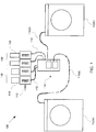
- FIG. 1 is a block diagram of a powdered and liquid chemical distribution system 100.
- the system 100 includes a chemical distribution hub 104 (sometimes referred to as a transport module) that dispenses and/or distributes water and one or more chemicals to devices, such as washers 102(a) and 102(b), along tubes or lines 116.
- a chemical distribution hub 104 sometimes referred to as a transport module
- devices such as washers 102(a) and 102(b)
- tubes or lines 116 tubes or lines 116.
- only a single tube or line is run to each device, unlike current systems which typically require more than one line to each device, as will be explained in further detail below.
- Water is supplied from one or more water sources 110, such as a municipal or city water supply.
- One or more powdered chemicals may be provided by one or more powdered chemical sources 106 that are coupled to the hub 104 via one or more tubes or lines 112.
- the water from the water source 110 is also provided to the hub 104 along the same lines 112 that supply the powdered chemical(s).
- the powdered chemical sources receive disposable powdered chemical refill containers 118.
- a suitable powdered chemical source and/or container is disclosed in Applicant's US Patent Publication No. US 2005/0247742A1 entitled "Metering and Dispensing Closure".
- one or more liquid chemicals may be provided by one or more liquid chemical sources 108 that are coupled to the hub 104 via one or more tubes or lines 114.
- the powdered chemical sources receive disposable liquid chemical refill containers 120.
- one or more liquid chemicals may be supplied from a tank that is refilled, or the like.
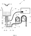
- Figure 2 is a partial cross-sectional view of the chemical distribution hub 104 of the chemical distribution system 100 shown in Figure 1 .
- the hub 104 includes three chambers. It should however be appreciated that more or less chambers may be used.
- the three chambers include a measuring chamber ("first chamber”) 208, a chemical chamber ("second chamber”) 210, and a transport chamber (“third chamber”) 206.
- the three chambers are aligned with one another in use so that the third chamber 206 is disposed vertically above the first chamber 208, and the first chamber 208 is disposed vertically above the second chamber 210, i.e., aligned along a vertical line that is perpendicular to the horizon.
- the three chambers are aligned with one another such that fluid can flow under a gravitational force from the third chamber 206 to the first chamber 208, and from the first chamber 208 to the second chamber 210.
- the first chamber 208 is defined by at least one first chamber wall.
- the first chamber wall is a circular wall that defines a cylinder having a first diameter D1.
- the volume of the chamber is selected such that any change in fluid level in the chamber is great enough to allow easy sensing of the change in pressure by a sensor, described below, while retaining the water volume low enough to allow rapid flushing at the end of a dose cycle.
- a suitable range of first diameters and heights of the first chamber are 0.5-2 inches and 4 to 10 inches, respectively.
- the first chamber 208 has a first chamber first end 242, an opposing first chamber second end 244, and a port 228.
- the first chamber first end 242 is configured to receive into the first chamber 208: (i) water 202, from a water source 110 ( Figure 1 ), and/or (ii) one or more powdered chemicals 204, from one or more powdered chemical sources 106 ( figure 1 ).
- the port 228 is formed in the first chamber wall. In some embodiments, the port 228 is situated near the first chamber second end 244. Also in some embodiments, the port has a diameter that is significantly larger than the pressure sensor input tube to create a trapped air pocket between the chamber and the pressure sensor input tube. Also in some embodiments, the diameter of the port 228 is chosen so that water is not drawn or held in the port by a capillary action. In some embodiments, the height of the first chamber that is used for calibration is in the range of 2 to 6 inches above the port 228.
- the port 228 allows fluid communication into the first chamber 208.
- the port 228 is configured to be coupled to a sensor 236.
- the sensor 236 is a pressure sensor, such as an absolute pressure sensor, that measures the head of fluid in the first chamber 208 above the port 228.
- the sensor 236 is disposed within a controller 214.
- the controller 214 is configured to calibrate the chemical distribution system, control the flow of water and chemicals into the hub 104, and control the flow of water and chemicals to the various devices 102 ( Figure 1 ), as described in further detail below.
- the second chamber 210 is defined by at least one second chamber wall.
- the second chamber wall is a circular wall that defines a cylinder having a second diameter D2.
- the first diameter D1 i.e., the diameter of the first chamber is larger than the second diameter D2, i.e., the diameter of the second chamber.
- the second diameter is chosen to be large enough to allow liquid chemicals to be injected into the second chamber, but small enough to facilitate high velocities of water to flush any liquid chemical residue from the second chamber.
- a suitable range second diameters and heights of the second chamber are 0.25 to 1.75 inches and 5 to 11 inches, respectively.
- the second chamber 210 has a second chamber first end 246, an opposing second chamber second end 248, and one or more chemical inlets 230 in the at least one second chamber wall.
- the second chamber first end 246 is configured to be coupled to the first chamber second end 244.
- Each of the one or more chemical inlets 246 allows fluid communication into the second chamber 210.
- each of the chemical inlets is configured to be coupled to a different liquid chemical source 108 ( Figure 1 ). Where multiple chemical inlets are provided, but fewer chemical sources are provided, the additional inlets may be capped.
- Each chemical inlet 230 coupled to a chemical source is coupled to a tube or line 114, such as a flexible plastic tube, that is coupled to the chemical source.
- each of these chemical inlets 230 is coupled to a respective chemical source via a chemical pump 216, as shown.
- a chemical pump 216 for example, a flexible plastic tube transporting a liquid chemical may be inserted through a positive displacement pump, such as a peristaltic pump.
- each chemical pump 216 is located within a respective liquid chemical source 108.
- the manifold 212 has a manifold inlet 250 fluidly coupled to the second chamber second end 248.
- the manifold may be coupled to the second chamber second end via a tube or line (see Figure 6 ).
- the manifold also includes one or more manifold outlets 232 each configured to be coupled to a different device 102 ( Figure 1 ). Where multiple manifold outlets 232 are provided, but fewer devices are provided, the additional outlets may be capped.
- Each manifold outlet 232 coupled to a device is coupled to a tube or line 116, such as a flexible plastic tube, that is coupled to the chemical source.
- each of these manifold outlets 232 is coupled to a respective device via a transport pump 218, as shown.
- a flexible plastic tube transporting water and a chemical to a device may be inserted through a positive displacement pump, such as a peristaltic pump.
- the third chamber 206 is defined by at least one third chamber wall.
- the third chamber wall is a circular wall that defines a cylinder having a third diameter D3.
- the third diameter D3, i.e., the diameter of the third chamber is larger than the first diameter D1, i.e., the diameter of the first chamber.
- the third chamber 206 has a larger diameter to facilitate larger volumes of, particularly of water, to be transported once calibration has taken place.
- the larger diameter also provides an overflow volume in case of failure of the sensor 236, i.e., if the sensor fails, the water entering the third chamber can rise without overflowing until the flow of water is automatically stopped by the controller after a predetermined time period.
- a suitable range of third diameters are 3 to 7 inches.
- the third chamber 206 includes a third chamber first end 252 and a third chamber second end 254.
- the third chamber first end 252 is configured to receive water 202 and chemicals 204 into the third chamber 206.
- water 202 is received from at least one water source 110 ( Figure 1 ) and one or more powdered chemical(s) 204 are received from the powdered chemical source(s) 106 ( Figure 1 ).
- the third chamber second end 254 is located opposite the third chamber first end 252.
- the third chamber second end 254 is fluidly coupled to the first chamber first end 242.
- the chemical distribution system may first be initialized to: ensure that the water level is known and ready for feed or distribution, to measure sensor offset, and to compensate for drift of the sensor output.
- the controller 214 may verify communication with the remote chemical sources, valves, pumps, etc.
- One or more of the transport pump(s) 218 are then run until the sensor 236 measures that the level in the first chamber has stopped dropping, i.e., the fluid in the first chamber has dropped below the port 228.
- the controller then records the sensor output as zero offset, which is used to adjust all readings during feed or distribution to the devices. If the sensor continues to report that the level is dropping after a predetermined time period, then an error exists and the user is notified.
- the system checks that the transport pump and water supply are operational before starting to pump chemicals.
- the water supply 110 ( Figure 1 ) is turned on and the system waits for the level to rise above the sensor to a predetermined level.
- One or more of the transport pumps 218 are then turned on and the controller 214 waits for the level in the first chamber 208 to drop to just above the port 228. At that time, the transport pump is turned off.
- the chemical(s) to be dispensed (typically a liquid chemical) are introduced into the second chamber 210 via one or more of the chemical inlets 230. This may be accomplished by turning on the chemical pump(s) 216.
- the entry of the chemical(s) into the second chamber 210 causes the water in the first chamber 208 to rise.
- the resulting change in water level in the first chamber is detected by the sensor 236, i.e., the sensor detects the change in head (pressure) in the first chamber.
- the increase in pressure is used to determine the volume of chemical(s) being injected.
- the chemical to be dispensed (typically a liquid chemical) is introduced into the second chamber 210 via one or more of the chemical inlets 230. This may be accomplished by turning on the chemical pump 216.
- the entry of the chemical into the second chamber 210 causes the water in the first chamber 208 to rise.
- the resulting change in water level in the first chamber is detected by the sensor 236, i.e., the sensor detects the change in head (pressure) in the first chamber.
- the increase in pressure is used to determine the volume of chemical being injected.
- flow of the chemical into the second chamber 210 is stopped by the controller 214 turning off the chemical pump 216.
- the controller 214 also measures the time that it takes the chemical pump 216 to inject the predetermined volume.
- the controller 14 uses the predetermined volume and the measured time to determine the flow rate of the liquid chemical being injected by the chemical pump 216. Using this calculated flow rate, the controller turns on the chemical pump 216, a flow of water, and the transport pump 218 until the larger dosages of liquid chemical has been dispensed and distributed.
- the controller maintains the level of water in the third chamber by measuring the pressure and turning on or off the transport pump 218 and/or water flow into the third chamber.
- the larger volume of the third chamber allows for some variation in water volume in the third chamber as the level is maintained. In this way larger dosages of liquid chemicals may be distributed to a desired device 102 ( Figure 1 ).
- the water that follows the chemical(s) to the device has the added advantage of flushing the chemical distribution system of the chemical(s).
- a known dose of powdered chemical 204 and water 202 is introduced into top of the third chamber 206.
- the water and powdered chemical mix is then distributed to a desired device 102 ( Figure 1 ).
- An advantage of this system is that the powdered chemicals may be distributed to each device along the same single line as the liquid chemicals. This may be accomplished by, for example, turning on one of the transport pumps 218. More water may then be injected into the third chamber 206 to flush the chemical distribution system of the chemical.
- the above described chemical distribution system and method allows the controller 214 to accurately dispense a desired dose of powdered and/or liquid chemicals to a ware wash or laundry washer along a single tube or line 116.
- Figure 3 is a partial cross-sectional view of another chemical distribution hub 300.
- Chemical distribution hub 300 is configured to receive water 302, one or more powdered chemicals 304, and one or more liquid chemicals 305.
- the hub 300 includes only a single chamber 307.
- the chamber 307 is defined by at least one chamber wall.
- the chamber wall is a circular wall that defines a cylinder having a predetermined diameter D.
- the volume of the chamber is selected such that any change in fluid level in the chamber is great enough to allow easy sensing of the change in pressure by a sensor, while retaining the water volume low enough to allow rapid flushing at the end of a dose cycle.
- a port 308 is formed in the chamber wall that allows fluid communication into the chamber.
- the port 308 is coupled to a sensor.
- the sensor is a pressure sensor, such as an absolute pressure sensor, that measures the head of fluid above the port 308.
- the sensor 236 ( Figure 2 ) is disposed within a controller (not shown), which calibrates the chemical distribution system, controls the flow of water and chemicals into the hub, and controls the flow of water and chemicals to the various devices 102 ( Figure 1 ).
- the chamber 307 also includes one or more liquid chemical inlets 310 in the chamber wall below the port 308, and one or more outlets 312 that are each configured to be coupled to a different device 102 ( Figure 1 ).
- liquid chemicals 306 are introduced into the chamber through the chemical inlets 310
- powdered chemicals 304 are introduced into the chamber through the top of the chamber 322.
- the water and chemicals are distributed to the devices through the outlets 312. Calibration, dosage, measurement, distribution and other control occurs in a similar manner to that described above in relation to Figure 2 .
- FIG 4 is a perspective view of the chambers component of a chemical distribution hub 400, according to another embodiment of the invention.
- the hub 400 includes many of the same components as described above in relation to Figure 2 .
- hub 4 includes a first chamber 404 that is similar to the first chamber 208 ( Figure 2 ), a second chamber 408 that is similar to the second chamber 210 ( Figure 2 ), a third chamber 402 that is similar to the third chamber 206 ( Figure 2 ), three chemical inlets 410 that are similar to the chemical inlets 230 ( Figure 2 ), and a port 406 coupled to a sensor that is similar to the port 228 ( Figure 2 ).
- the port 406 is disposed at an acute angle to the first chamber wall so that the port drains as the water level drops during flushing of water and chemical(s) to the devices 102 ( Figure 1 ).
- each of the first, second, and third chambers are shown in Figure 2 as having stepped boundaries, in this embodiment the boundaries between chambers are graduated, e.g., the diameters of the chambers change gradually so that fluid easily drains from the chambers and there is no powder build-up.
- the hub 400 also includes an outlet port 412 that is coupled to a manifold via tube or line, as shown and described in relation to Figure 6 .
- a suitable range of diameters for the outlet port 412 is 1/8 to 1 inches.
- FIG. 5 is a top view looking into the third chamber 402 of Figure 4 .
- a baffle 502 is positioned in the first chamber 402 above the port 406.
- the baffle 502 may be coupled to the wall of the first chamber.
- the baffle 502 is formed in an angled shape to deflect water and chemicals away from the port 406.
- the baffle 502 may be formed from the same material as the first, second, and third chambers, and in some embodiments may be injection molded together as a single piece together with the first, second, and third chambers, port, and chemical inlets.
- FIG 6 is a perspective view of additional components of the hub 400 shown in Figure 4 .
- This view of the hub 400 includes the chambers shown in Figure 4 .
- the outlet 412 is fluidly coupled to a manifold 604 via a flexible tube or pipe 602.
- the three outlets from the manifold are in turn fluidly coupled to three separate transport pumps 608 via flexible tubes or lines.
- the transport pumps are peristaltic pumps.
- Each of the flexible tubes or lines exiting the manifold is configured to be fluidly coupled to a separate device, such as a washer.
- the chambers, manifold 604, and pumps 608 are coupled to a mounting plate 606 to allow the hub 400 to be wall mounted.
- the hub 400 may also house the controller 214 ( Figure 2 ).
- a housing (not shown) may connect to the mounting plate 606 to enclose the above described components.
Landscapes
- Engineering & Computer Science (AREA)
- Textile Engineering (AREA)
- Feeding, Discharge, Calcimining, Fusing, And Gas-Generation Devices (AREA)
- Washing And Drying Of Tableware (AREA)
- Detergent Compositions (AREA)
- Cleaning By Liquid Or Steam (AREA)
- Branch Pipes, Bends, And The Like (AREA)
Claims (16)
- Verteilungssystem für pulverförmige und flüssige Chemikalien, das aufweist:ein Verteilungszentrum (104) für Chemikalien, wobei das Verteilungszentrum (104) für Chemikalien eine erste Kammer (208), eine zweite Kammer (210), einen Verteiler (212) und eine Steuereinheit (214) aufweist,wobei die Steuereinheit (214) dazu ausgestaltet ist, den Fluss von Wasser und Chemikalien in das Zentrum (104) zu steuern,wobei ein Sensor (236) mit der Steuereinheit (214) verbunden ist,wobei die erste Kammer (208) durch eine erste Kammerwand definiert ist,wobei die erste Kammer aufweist:ein erstes Ende (242) einer ersten Kammer, das dazu ausgestaltet ist, Wasser in der ersten Kammer aufzunehmen, wobei das Wasser einen Wasserstand in der ersten Kammer definiert, und das erste Ende der ersten Kammer weiterhin dazu ausgestaltet ist, eine pulverförmige Chemikalie in der ersten Kammer aufzunehmen;ein zweites Ende (244) der ersten Kammer gegenüberliegend zum ersten Ende der ersten Kammer; undeinen Anschluss (228) in der ersten Kammerwand, wobei der Anschluss (228) mit dem Sensor (236) verbunden ist;wobei die zweite Kammer (210) durch eine zweite Kammerwand definiert ist, wobei die zweite Kammer aufweist:ein erstes Ende (246) der zweiten Kammer, das in Fluidverbindung mit dem zweiten Ende der ersten Kammer steht, um Wasser und die eine oder die mehreren pulverförmige(n) Chemikalie(n) aus der ersten Kammer aufzunehmen;ein zweites Ende (248) der zweiten Kammer gegenüberliegend zum ersten Ende der zweiten Kammer; undeinen oder mehrere Einlässe (230) für flüssige Chemikalien in der zweiten Kammerwand, wobei ein jeder der Einlässe für flüssige Chemikalien dazu ausgestaltet ist, mit einer anderen Quelle (108) einer flüssigen Chemikalie verbunden zu sein, um eine flüssige Chemikalie aus der Quelle (108) der flüssigen Chemikalie aufzunehmen; und wobei der Verteiler (212) aufweist:einen Verteilereinlass (250), der in Fluidverbindung mit dem zweiten Ende der zweiten Kammer steht; undeinen Verteilerauslass (232), der dazu ausgestaltet ist,mit einer Vorrichtung (102) verbunden zu werden;wobei die Steuereinheit dazu ausgestaltet ist, den Fluss eines beliebigen Fluids aus dem Verteiler (212) zu stoppen,bevor die zweite Kammer (210) die flüssige Chemikalie aufnimmt:wobei die flüssige Chemikalie, die in der zweiten Kammer (210), nachdem der Fluss des Fluids aus dem Verteiler (250) gestoppt wurde, aufgenommen wird, einen Anstieg im Wasserstand in der ersten Kammer (208) bewirkt, bis ein gewünschtes Volumen der flüssigen Chemikalie eingeleitet wurde, wie durch den Sensor erfasst,wobei die Steuereinheit dazu ausgestaltet ist, zu ermöglichen, dass eine flüssige Chemikalie und Wasser aus der zweiten Kammer zu dem Verteiler fließen, nachdem das gewünschte Volumen der flüssigen Chemikalie eingeleitet wurde,wobei die Steuereinheit (214) dazu ausgestaltet ist, eine gewünschte Dosis einer pulverförmigen Chemikalie und einer flüssigen Chemikalie an die Vorrichtung (102) auszugeben, undwobei die erste Kammer und die zweite Kammer in einer Beziehung einer Fluidreihe dergestalt angeordnet sind, dass die pulverförmige Chemikalie und das Wasser von der ersten Kammer durch die zweite Kammer fließen.
- Verteilungssystem für pulverförmige und flüssige Chemikalien nach Anspruch 1, das weiterhin eine dritte Kammer (206) aufweist, die durch eine dritte Kammerwand definiert ist, wobei die dritte Kammer aufweist:ein erstes Ende (252) einer dritten Kammer, das dazu ausgestaltet ist, Wasser von einer Wasserquelle (110) und die pulverförmige Chemikalie von einer Quelle (106) einer pulverförmige Chemikalie in die dritte Kammer aufzunehmen; undein zweites Ende (254) der dritten Kammer gegenüberliegend zum ersten Ende der dritten Kammer, wobei das zweite Ende der dritte Kammers in Fluidverbindung mit dem ersten Ende der ersten Kammer steht, sodass die pulverförmige Chemikalie und das Wasser in die erste Kammer (208) fließen.
- Verteilungssystem für pulverförmige und flüssige Chemikalien nach Anspruch 2, wobei die dritte Kammer ein größeres Volumen als die erste Kammer aufweist, und die erste Kammer ein größeres Volumen als die zweite Kammer aufweist.
- Verteilungssystem für pulverförmige und flüssige Chemikalien nach Anspruch 2, wobei das System dazu ausgestaltet ist, zu ermöglichen, dass ein Fluid unter Einwirkung einer Gravitationskraft von dem ersten Ende der dritten Kammer zu dem zweiten Ende der zweiten Kammer fließt.
- Verteilungssystem für pulverförmige und flüssige Chemikalien nach Anspruch 1, wobei das Volumen der erste Kammer größer ist als das der zweiten Kammer.
- Verteilungssystem für pulverförmige und flüssige Chemikalien nach Anspruch 1, wobei das System während des Gebrauchs dazu angeordnet ist, zu ermöglichen, dass ein Fluid unter Einwirkung einer Gravitationskraft von dem ersten Ende der ersten Kammer zu dem zweiten Ende der zweiten Kammer fließt.
- Verteilungssystem für pulverförmige und flüssige Chemikalien nach Anspruch 1, wobei der Sensor ein Drucksensor ist, der zum Bestimmen der Höhe des Fluids über dem Anschluss in der ersten Kammer verwendet wird.
- Verteilungssystem für pulverförmige und flüssige Chemikalien nach Anspruch 1, wobei ein jeder der Einlässe für flüssige Chemikalien dazu ausgestaltet ist, in Fluidverbindung mit einer anderen Quelle einer flüssigen Chemikalie über eine andere Pumpe zu stehen.
- Verteilungssystem für pulverförmige und flüssige Chemikalien nach Anspruch 1, wobei der Verteilerauslass wenigstens zwei Verteilerauslässe aufweist, die jeweils über eine andere Waschmaschinenpumpe mit einer Waschmaschine verbunden sind.
- Verteilungssystem für pulverförmige und flüssige Chemikalien nach Anspruch 2, das weiterhin aufweist:eine Ausgabevorrichtung für Flüssigkeiten, die dazu ausgebildet ist, die flüssige Chemikalie in die zweite Kammer auszugeben, undeine Ausgabevorrichtung für pulverförmige Chemikalien, die dazu ausgebildet ist, die pulverförmige Chemikalie in die dritte Kammer auszugeben.
- Verteilungssystem für pulverförmige und flüssige Chemikalien nach Anspruch 2, wobei das System dazu ausgestaltet ist, zu ermöglichen, dass ein Fluid unter Einwirkung einer Gravitationskraft von der dritten Kammer zum Verteiler fließt.
- Verteilungssystem für pulverförmige und flüssige Chemikalien nach Anspruch 2, wobei ein jeder der Einlässe für flüssige Chemikalien dazu ausgestaltet ist, in Fluidverbindung mit einer anderen Quelle einer flüssigen Chemikalie über eine andere Pumpe für eine flüssige Chemikalie zu stehen, und wobei das erste Ende der dritten Kammer dazu ausgestaltet ist, Wasser aus der Wasserquelle und die pulverförmige Chemikalie aus der Quelle der pulverförmigen Chemikalie aufzunehmen und wobei der Verteilerauslass mehrere Verteilerauslässe aufweist, von denen ein jeder mit einer Waschmaschine über eine Waschmaschinenpumpe verbunden ist, wobei das System weiterhin ein Steuerungssystem aufweist, das elektronisch mit dem Sensor, den Pumpen, der Wasserquelle und der Quelle der pulverförmigen Chemikalie verbunden ist, um die Verteilung der flüssigen Chemikalie und der pulverförmigen Chemikalie zu jeder Waschmaschine zu steuern.
- Verteilungssystem für pulverförmige und flüssige Chemikalien nach Anspruch 1 oder 2, wobei das System ein Transportmodul aufweist, das dazu ausgestaltet ist sowohl die pulverförmige Chemikalie als auch die flüssige Chemikalie automatisch zur Vorrichtung entlang einer einzelnen Leitung (116) zu transportieren.
- Verteilungssystem für pulverförmige und flüssige Chemikalien nach Anspruch 13, wobei das System dazu ausgestaltet ist, die pulverförmige Chemikalie und die flüssige Chemikalie automatisch an verschiedene Vorrichtungen entlang verschiedener einzelner Leitungen zu transportieren.
- Verfahren zum Verteilen von pulverförmigen und flüssigen Chemikalien an eine Vorrichtung unter Verwendung eines chemischen Verteilungssystems nach einem der vorhergehenden Ansprüche, wobei das chemische Verteilungssystem eine erste und zweite Kammer aufweist, das aufweist:Einleiten von Wasser in ein oberes Ende der ersten Kammer, wobei das Wasser einen Wasserstand in der ersten Kammer definiert;Einspritzen einer flüssigen Chemikalie in die zweite Kammer, die in Fluidverbindung mit einem unteren Ende der ersten Kammer steht, wobei die in der zweiten Kammer aufgenommene flüssige Chemikalie zu einem Anstieg des Wasserstands in der ersten Kammer führt, der von einem mit einer Steuereinheit verbundenen Sensor erfasst wird, bis das gewünschte Volumen der flüssigen Chemikalie eingeleitet worden ist; Pumpen des gewünschten Volumens der flüssigen Chemikalie und von wenigstens etwas des Wassers in die Vorrichtung;Einleiten von Wasser und einer gewünschten Dosis einer pulverförmigen Chemikalie in das obere Ende der ersten Kammer; Transportieren der flüssigen Chemikalie und von wenigstens etwas Wasser in die Vorrichtung.
- Verfahren nach Anspruch 15, wobei die flüssige Chemikalie und das Wasser mit der pulverförmigen Chemikalie mittels eines einzigen Rohrs oder Leitung in die Vorrichtung transportiert werden.
Priority Applications (1)
| Application Number | Priority Date | Filing Date | Title |
|---|---|---|---|
| EP18193800.2A EP3434820A1 (de) | 2006-03-30 | 2007-03-16 | Ausgabe- und verteilungssystem für pulverförmige und flüssige chemikalien |
Applications Claiming Priority (2)
| Application Number | Priority Date | Filing Date | Title |
|---|---|---|---|
| US78758306P | 2006-03-30 | 2006-03-30 | |
| PCT/US2007/064200 WO2007146458A2 (en) | 2006-03-30 | 2007-03-16 | Powdered and liquid chemical dispensing and distribution system |
Related Child Applications (1)
| Application Number | Title | Priority Date | Filing Date |
|---|---|---|---|
| EP18193800.2A Division EP3434820A1 (de) | 2006-03-30 | 2007-03-16 | Ausgabe- und verteilungssystem für pulverförmige und flüssige chemikalien |
Publications (2)
| Publication Number | Publication Date |
|---|---|
| EP2007938A2 EP2007938A2 (de) | 2008-12-31 |
| EP2007938B1 true EP2007938B1 (de) | 2018-09-12 |
Family
ID=38267943
Family Applications (2)
| Application Number | Title | Priority Date | Filing Date |
|---|---|---|---|
| EP18193800.2A Withdrawn EP3434820A1 (de) | 2006-03-30 | 2007-03-16 | Ausgabe- und verteilungssystem für pulverförmige und flüssige chemikalien |
| EP07815099.2A Active EP2007938B1 (de) | 2006-03-30 | 2007-03-16 | Ausgabe- und verteilungssystem für pulverförmige und flüssige chemikalien |
Family Applications Before (1)
| Application Number | Title | Priority Date | Filing Date |
|---|---|---|---|
| EP18193800.2A Withdrawn EP3434820A1 (de) | 2006-03-30 | 2007-03-16 | Ausgabe- und verteilungssystem für pulverförmige und flüssige chemikalien |
Country Status (7)
| Country | Link |
|---|---|
| US (3) | US8240514B2 (de) |
| EP (2) | EP3434820A1 (de) |
| JP (1) | JP5055356B2 (de) |
| BR (1) | BRPI0710040B1 (de) |
| CA (2) | CA2647627C (de) |
| DK (1) | DK2007938T3 (de) |
| WO (1) | WO2007146458A2 (de) |
Families Citing this family (17)
| Publication number | Priority date | Publication date | Assignee | Title |
|---|---|---|---|---|
| EP3434820A1 (de) * | 2006-03-30 | 2019-01-30 | Diversey, Inc. | Ausgabe- und verteilungssystem für pulverförmige und flüssige chemikalien |
| DE602007012225D1 (de) * | 2007-07-03 | 2011-03-10 | Electrolux Home Prod Corp | Waschmaschine |
| DE102007048199B3 (de) | 2007-10-08 | 2009-01-15 | Miele & Cie. Kg | Dosiereinrichtung für pulverförmiges Behandlungsmittel für eine Waschmaschine und Waschmaschine |
| DE102007048197A1 (de) | 2007-10-08 | 2009-04-16 | Miele & Cie. Kg | Dosiereinrichtung für Behandlungsmittel für eine Waschmaschine und Waschmaschine |
| US8555678B2 (en) | 2008-12-09 | 2013-10-15 | Lg Electronics Inc. | Washing machine system and washing method |
| DE102010027991A1 (de) * | 2010-04-20 | 2011-10-20 | Henkel Ag & Co. Kgaa | Dosiersystem zur Verwendung in Verbindung mit einem wasserführenden Haushaltsgerät wie eine Waschmaschine, Spülmaschine, Wäschetrockner oder dergleichen |
| US9618376B2 (en) | 2010-07-30 | 2017-04-11 | Ecolab Usa Inc. | Apparatus, method and system for calibrating a liquid dispensing system |
| EP2598684B1 (de) | 2010-07-30 | 2020-12-16 | Ecolab USA Inc. | Vorrichtung zur kalibrierung eines flüssigkeitsausgabesystems |
| AU2012352338B2 (en) * | 2011-12-13 | 2016-12-15 | Ecolab Usa Inc. | Dishmachine |
| DE102014002560A1 (de) * | 2014-02-26 | 2015-08-27 | Beatrice Saier | System zur Erfassung des Verbrauchs eines Mediums in einer Wasch- oder Reinigungsanlage u.a. |
| US11690309B2 (en) | 2015-07-23 | 2023-07-04 | Zito Jr Arthur J | Responsive dispersion from compartment in aqueous solution |
| CN110770385B (zh) * | 2017-08-23 | 2026-05-01 | 松下知识产权经营株式会社 | 洗衣机 |
| US12408638B2 (en) | 2018-01-19 | 2025-09-09 | Arthur J. Zito, Jr. | Responsive dispersion from compartment in aqueous solution |
| EP3810542B1 (de) | 2018-06-25 | 2024-06-12 | Conceptr Partners Llc | Flüssigkeitsintegrierendes system zur herstellung einer integrierten flüssigkeit nach dem oberbegriff des anspruchs 1 |
| US11242640B2 (en) | 2018-12-31 | 2022-02-08 | Whirlpool Corporation | Household appliance with single-use dispenser for bulk dispenser filling |
| EP4051077A1 (de) | 2019-11-01 | 2022-09-07 | Unilever IP Holdings B.V. | Wiederverwertbarer autodosierender behälter |
| US12590397B2 (en) * | 2021-04-19 | 2026-03-31 | Rochester Midland Corporation | Industrial laundry systems and methods |
Family Cites Families (33)
| Publication number | Priority date | Publication date | Assignee | Title |
|---|---|---|---|---|
| US3570717A (en) * | 1969-01-08 | 1971-03-16 | Stauffer Chemical Co | System for fluent material dispensing with electrical controls |
| US3881328A (en) * | 1971-12-22 | 1975-05-06 | Economics Lab | Electronic detergent dispensing system |
| AR208392A1 (es) * | 1973-05-07 | 1976-12-27 | Henkel & Cie Gmbh | Composicion para lavar blanquear o limpiar materiales resistentes especialmente textiles adicional a la patente no 201687 adicional a la no 253286 |
| IT209171Z2 (it) * | 1985-11-14 | 1988-09-16 | Zanussi Elettrodomestici | Dispositivo contenitore-erogatore di detersivi per macchina lavabiancheria. |
| US4700554A (en) * | 1986-02-19 | 1987-10-20 | Whirlpool Corporation | Detergent dispenser with improved water distribution means |
| US4898202A (en) * | 1987-07-27 | 1990-02-06 | Craig James R | Fertilizer container for sprinkler system |
| DE8711341U1 (de) * | 1987-08-21 | 1988-09-22 | Licentia Patent-Verwaltungs-Gmbh, 6000 Frankfurt | Waschmaschine |
| JPH04338488A (ja) * | 1991-05-16 | 1992-11-25 | Matsushita Electric Ind Co Ltd | 電気洗濯機及び洗剤容器 |
| CA2171716C (en) * | 1993-09-27 | 1999-03-23 | James W. Livingston | Flow-metered pumping with load compensation system and method |
| US5435157A (en) * | 1994-01-27 | 1995-07-25 | Sunburst Chemicals, Inc. | Laundry chemical dispenser |
| US5678593A (en) * | 1994-05-27 | 1997-10-21 | Lockhart; Barton | Detergent mixing apparatus |
| US5500050A (en) * | 1994-07-15 | 1996-03-19 | Diversey Corporation | Ratio feed detergent controller and method with automatic feed rate learning capability |
| US5870906A (en) * | 1996-04-03 | 1999-02-16 | Denisar; Richard A. | Automatic dispensing device |
| GB2348709B (en) | 1997-02-19 | 2001-03-28 | Ecolab Inc | Dispensing system with multi-port valve for distributing use dilution to a plurality of utilization points and position sensor for use thereon |
| US6223129B1 (en) * | 1998-05-13 | 2001-04-24 | Diverseylever, Inc. | Apparatus and method for conductivity measurement including probe contamination compensation |
| US6691536B2 (en) * | 2000-06-05 | 2004-02-17 | The Procter & Gamble Company | Washing apparatus |
| JP2002102589A (ja) * | 2000-10-02 | 2002-04-09 | Matsushita Electric Ind Co Ltd | 洗濯機等の洗剤投入装置 |
| US6434977B1 (en) * | 2000-10-06 | 2002-08-20 | Ark-Les Corporation | Automatic laundry aid dispenser for washing machine |
| DE10103091A1 (de) * | 2001-01-24 | 2002-08-01 | Ecolab Gmbh & Co Ohg | Verfahren zur Herstellung, Förderung und Dosierung einer Lösung und Vorrichtung zur Durchführung des Verfahrens |
| US7143778B2 (en) * | 2001-12-04 | 2006-12-05 | Arch Chemicals, Inc. | Chemical feeder |
| US6978911B2 (en) * | 2001-12-19 | 2005-12-27 | Auto Wax Company, Inc. | Apparatus and methods for producing and dispensing automobile appearance care products charged to a customer on a selected bases |
| US6880191B2 (en) * | 2001-12-31 | 2005-04-19 | Joe G. Bristor | Spray caddy and method of dispensing chemicals |
| CN1256478C (zh) * | 2002-01-11 | 2006-05-17 | Lg电子株式会社 | 在洗衣机中供应洗涤剂的设备 |
| US6826933B2 (en) * | 2002-02-06 | 2004-12-07 | Maytag Corporation | Dual use detergent dispenser |
| US6779539B1 (en) * | 2003-02-26 | 2004-08-24 | Johnsondiversey, Inc. | Dispensing apparatus for delivering controlled amounts of water soluble material to a process stream |
| DE10358969A1 (de) * | 2003-12-16 | 2005-07-21 | BSH Bosch und Siemens Hausgeräte GmbH | Geschirrspülmaschine mit einer Dosiervorrichtung für Zuschlagmittel und zugehöriges Verfahren |
| ATE398486T1 (de) * | 2004-01-02 | 2008-07-15 | Ecolab Inc | Verfahren und vorrichtung zur herstellung einer waschmittelvorratslösung für industrielle waschmaschinen |
| US20050183208A1 (en) * | 2004-02-20 | 2005-08-25 | The Procter & Gamble Company | Dual mode laundry apparatus and method using the same |
| KR101082561B1 (ko) * | 2004-04-14 | 2011-11-10 | 엘지전자 주식회사 | 세탁기의 세제 공급장치 |
| US7090098B2 (en) | 2004-05-06 | 2006-08-15 | Johnsondiversey, Inc. | Metering and dispensing closure |
| US7398787B2 (en) * | 2004-10-18 | 2008-07-15 | Unilever Home & Personal Care Usa Division Of Conopco, Inc. | Automatic dispensing device for laundry care composition |
| US7481081B2 (en) * | 2004-11-23 | 2009-01-27 | Unilever Home & Personal Care Usa Division Of Conopco, Inc. | Automatic stand-alone dispensing device for laundry care composition |
| EP3434820A1 (de) * | 2006-03-30 | 2019-01-30 | Diversey, Inc. | Ausgabe- und verteilungssystem für pulverförmige und flüssige chemikalien |
-
2007
- 2007-03-16 EP EP18193800.2A patent/EP3434820A1/de not_active Withdrawn
- 2007-03-16 CA CA2647627A patent/CA2647627C/en active Active
- 2007-03-16 US US12/293,745 patent/US8240514B2/en active Active
- 2007-03-16 CA CA2912081A patent/CA2912081C/en active Active
- 2007-03-16 BR BRPI0710040-0A patent/BRPI0710040B1/pt not_active IP Right Cessation
- 2007-03-16 DK DK07815099.2T patent/DK2007938T3/en active
- 2007-03-16 EP EP07815099.2A patent/EP2007938B1/de active Active
- 2007-03-16 WO PCT/US2007/064200 patent/WO2007146458A2/en not_active Ceased
- 2007-03-16 JP JP2009503142A patent/JP5055356B2/ja not_active Expired - Fee Related
-
2012
- 2012-05-30 US US13/483,675 patent/US8763856B2/en active Active
-
2014
- 2014-07-01 US US14/321,350 patent/US9725844B2/en active Active
Non-Patent Citations (1)
| Title |
|---|
| None * |
Also Published As
| Publication number | Publication date |
|---|---|
| JP5055356B2 (ja) | 2012-10-24 |
| CA2912081A1 (en) | 2007-12-21 |
| US20120247565A1 (en) | 2012-10-04 |
| CA2647627A1 (en) | 2007-12-21 |
| EP3434820A1 (de) | 2019-01-30 |
| CA2912081C (en) | 2017-09-26 |
| US8763856B2 (en) | 2014-07-01 |
| US9725844B2 (en) | 2017-08-08 |
| CA2647627C (en) | 2015-12-15 |
| WO2007146458A3 (en) | 2008-12-04 |
| EP2007938A2 (de) | 2008-12-31 |
| US20140312069A1 (en) | 2014-10-23 |
| BRPI0710040A2 (pt) | 2011-08-02 |
| US20100237169A1 (en) | 2010-09-23 |
| JP2009532108A (ja) | 2009-09-10 |
| BRPI0710040B1 (pt) | 2017-12-26 |
| WO2007146458A2 (en) | 2007-12-21 |
| DK2007938T3 (en) | 2018-12-10 |
| US8240514B2 (en) | 2012-08-14 |
Similar Documents
| Publication | Publication Date | Title |
|---|---|---|
| US8240514B2 (en) | Powdered and liquid chemical dispensing and distribution system | |
| KR101936536B1 (ko) | 유체 가공 시스템 및 방법 | |
| US9290884B2 (en) | Dosing apparatus and method for dosing a composition | |
| RU2558190C2 (ru) | Дозатор для дозирования раствора твердого вещества, растворенного в нем | |
| WO2008079202A1 (en) | Measuring fluid quantities, blending liquid constituents, and dispensing blends | |
| US9475022B2 (en) | Apparatus for producing a liquid concentrate from a dry material | |
| CN116867728A (zh) | 具有由单个半透膜覆盖的多个配料储存器的可加压料筒、包括该料筒的流体混合物分配系统、用于分配混合物的方法 | |
| JP2008224672A (ja) | 一定速度での液体の提供及び厳密に再現可能な容積の液体供給方法並びに装置 | |
| EP1750103B1 (de) | Vorrichtung zur Abgabe von Fluid, und darauf bezogenes Verfahren | |
| RU2417830C2 (ru) | Дозировочно-смесительное устройство для жидких продуктов и способ его работы | |
| US20130134184A1 (en) | Liquid metering and injection system | |
| KR20110072932A (ko) | 연속식 혼합장치를 이용한 재생약액 공급 장치 | |
| EP2342610A1 (de) | Zusatzstoffausgabesystem und -verfahren | |
| GB2198484A (en) | Syphons and liquid metering devices | |
| KR101661502B1 (ko) | 약액 혼합용 매니폴드 및 이를 포함하는 실시간 혼합 약액 공급 장치 | |
| CN223501816U (zh) | 一种供液系统及半导体湿法制程设备 | |
| CN202915051U (zh) | 补液装置 | |
| GB1589083A (en) | Device | |
| RU2736032C2 (ru) | Устройство для прецизионного дозирования жидкости | |
| RU1836625C (ru) | Дозатор |
Legal Events
| Date | Code | Title | Description |
|---|---|---|---|
| PUAI | Public reference made under article 153(3) epc to a published international application that has entered the european phase |
Free format text: ORIGINAL CODE: 0009012 |
|
| 17P | Request for examination filed |
Effective date: 20081027 |
|
| AK | Designated contracting states |
Kind code of ref document: A2 Designated state(s): AT BE BG CH CY CZ DE DK EE ES FI FR GB GR HU IE IS IT LI LT LU LV MC MT NL PL PT RO SE SI SK TR |
|
| AX | Request for extension of the european patent |
Extension state: AL BA HR MK RS |
|
| R17D | Deferred search report published (corrected) |
Effective date: 20081204 |
|
| RAP1 | Party data changed (applicant data changed or rights of an application transferred) |
Owner name: DIVERSEY, INC. |
|
| DAX | Request for extension of the european patent (deleted) | ||
| 17Q | First examination report despatched |
Effective date: 20160405 |
|
| STAA | Information on the status of an ep patent application or granted ep patent |
Free format text: STATUS: EXAMINATION IS IN PROGRESS |
|
| GRAP | Despatch of communication of intention to grant a patent |
Free format text: ORIGINAL CODE: EPIDOSNIGR1 |
|
| STAA | Information on the status of an ep patent application or granted ep patent |
Free format text: STATUS: GRANT OF PATENT IS INTENDED |
|
| INTG | Intention to grant announced |
Effective date: 20180404 |
|
| GRAS | Grant fee paid |
Free format text: ORIGINAL CODE: EPIDOSNIGR3 |
|
| GRAA | (expected) grant |
Free format text: ORIGINAL CODE: 0009210 |
|
| STAA | Information on the status of an ep patent application or granted ep patent |
Free format text: STATUS: THE PATENT HAS BEEN GRANTED |
|
| AK | Designated contracting states |
Kind code of ref document: B1 Designated state(s): AT BE BG CH CY CZ DE DK EE ES FI FR GB GR HU IE IS IT LI LT LU LV MC MT NL PL PT RO SE SI SK TR |
|
| REG | Reference to a national code |
Ref country code: GB Ref legal event code: FG4D |
|
| REG | Reference to a national code |
Ref country code: CH Ref legal event code: EP |
|
| REG | Reference to a national code |
Ref country code: IE Ref legal event code: FG4D |
|
| REG | Reference to a national code |
Ref country code: DE Ref legal event code: R096 Ref document number: 602007056136 Country of ref document: DE |
|
| REG | Reference to a national code |
Ref country code: AT Ref legal event code: REF Ref document number: 1040717 Country of ref document: AT Kind code of ref document: T Effective date: 20181015 |
|
| REG | Reference to a national code |
Ref country code: NL Ref legal event code: FP |
|
| REG | Reference to a national code |
Ref country code: DK Ref legal event code: T3 Effective date: 20181203 |
|
| REG | Reference to a national code |
Ref country code: LT Ref legal event code: MG4D |
|
| PG25 | Lapsed in a contracting state [announced via postgrant information from national office to epo] |
Ref country code: FI Free format text: LAPSE BECAUSE OF FAILURE TO SUBMIT A TRANSLATION OF THE DESCRIPTION OR TO PAY THE FEE WITHIN THE PRESCRIBED TIME-LIMIT Effective date: 20180912 Ref country code: BG Free format text: LAPSE BECAUSE OF FAILURE TO SUBMIT A TRANSLATION OF THE DESCRIPTION OR TO PAY THE FEE WITHIN THE PRESCRIBED TIME-LIMIT Effective date: 20181212 Ref country code: SE Free format text: LAPSE BECAUSE OF FAILURE TO SUBMIT A TRANSLATION OF THE DESCRIPTION OR TO PAY THE FEE WITHIN THE PRESCRIBED TIME-LIMIT Effective date: 20180912 Ref country code: GR Free format text: LAPSE BECAUSE OF FAILURE TO SUBMIT A TRANSLATION OF THE DESCRIPTION OR TO PAY THE FEE WITHIN THE PRESCRIBED TIME-LIMIT Effective date: 20181213 Ref country code: LT Free format text: LAPSE BECAUSE OF FAILURE TO SUBMIT A TRANSLATION OF THE DESCRIPTION OR TO PAY THE FEE WITHIN THE PRESCRIBED TIME-LIMIT Effective date: 20180912 |
|
| PG25 | Lapsed in a contracting state [announced via postgrant information from national office to epo] |
Ref country code: LV Free format text: LAPSE BECAUSE OF FAILURE TO SUBMIT A TRANSLATION OF THE DESCRIPTION OR TO PAY THE FEE WITHIN THE PRESCRIBED TIME-LIMIT Effective date: 20180912 Ref country code: ES Free format text: LAPSE BECAUSE OF FAILURE TO SUBMIT A TRANSLATION OF THE DESCRIPTION OR TO PAY THE FEE WITHIN THE PRESCRIBED TIME-LIMIT Effective date: 20180912 |
|
| REG | Reference to a national code |
Ref country code: AT Ref legal event code: MK05 Ref document number: 1040717 Country of ref document: AT Kind code of ref document: T Effective date: 20180912 |
|
| PG25 | Lapsed in a contracting state [announced via postgrant information from national office to epo] |
Ref country code: IS Free format text: LAPSE BECAUSE OF FAILURE TO SUBMIT A TRANSLATION OF THE DESCRIPTION OR TO PAY THE FEE WITHIN THE PRESCRIBED TIME-LIMIT Effective date: 20190112 Ref country code: PL Free format text: LAPSE BECAUSE OF FAILURE TO SUBMIT A TRANSLATION OF THE DESCRIPTION OR TO PAY THE FEE WITHIN THE PRESCRIBED TIME-LIMIT Effective date: 20180912 Ref country code: AT Free format text: LAPSE BECAUSE OF FAILURE TO SUBMIT A TRANSLATION OF THE DESCRIPTION OR TO PAY THE FEE WITHIN THE PRESCRIBED TIME-LIMIT Effective date: 20180912 Ref country code: CZ Free format text: LAPSE BECAUSE OF FAILURE TO SUBMIT A TRANSLATION OF THE DESCRIPTION OR TO PAY THE FEE WITHIN THE PRESCRIBED TIME-LIMIT Effective date: 20180912 Ref country code: EE Free format text: LAPSE BECAUSE OF FAILURE TO SUBMIT A TRANSLATION OF THE DESCRIPTION OR TO PAY THE FEE WITHIN THE PRESCRIBED TIME-LIMIT Effective date: 20180912 Ref country code: RO Free format text: LAPSE BECAUSE OF FAILURE TO SUBMIT A TRANSLATION OF THE DESCRIPTION OR TO PAY THE FEE WITHIN THE PRESCRIBED TIME-LIMIT Effective date: 20180912 |
|
| PG25 | Lapsed in a contracting state [announced via postgrant information from national office to epo] |
Ref country code: PT Free format text: LAPSE BECAUSE OF FAILURE TO SUBMIT A TRANSLATION OF THE DESCRIPTION OR TO PAY THE FEE WITHIN THE PRESCRIBED TIME-LIMIT Effective date: 20190112 Ref country code: SK Free format text: LAPSE BECAUSE OF FAILURE TO SUBMIT A TRANSLATION OF THE DESCRIPTION OR TO PAY THE FEE WITHIN THE PRESCRIBED TIME-LIMIT Effective date: 20180912 |
|
| REG | Reference to a national code |
Ref country code: DE Ref legal event code: R097 Ref document number: 602007056136 Country of ref document: DE |
|
| PLBE | No opposition filed within time limit |
Free format text: ORIGINAL CODE: 0009261 |
|
| STAA | Information on the status of an ep patent application or granted ep patent |
Free format text: STATUS: NO OPPOSITION FILED WITHIN TIME LIMIT |
|
| 26N | No opposition filed |
Effective date: 20190613 |
|
| PG25 | Lapsed in a contracting state [announced via postgrant information from national office to epo] |
Ref country code: SI Free format text: LAPSE BECAUSE OF FAILURE TO SUBMIT A TRANSLATION OF THE DESCRIPTION OR TO PAY THE FEE WITHIN THE PRESCRIBED TIME-LIMIT Effective date: 20180912 |
|
| PG25 | Lapsed in a contracting state [announced via postgrant information from national office to epo] |
Ref country code: MC Free format text: LAPSE BECAUSE OF FAILURE TO SUBMIT A TRANSLATION OF THE DESCRIPTION OR TO PAY THE FEE WITHIN THE PRESCRIBED TIME-LIMIT Effective date: 20180912 |
|
| REG | Reference to a national code |
Ref country code: CH Ref legal event code: PL |
|
| PG25 | Lapsed in a contracting state [announced via postgrant information from national office to epo] |
Ref country code: LU Free format text: LAPSE BECAUSE OF NON-PAYMENT OF DUE FEES Effective date: 20190316 |
|
| REG | Reference to a national code |
Ref country code: BE Ref legal event code: MM Effective date: 20190331 |
|
| PG25 | Lapsed in a contracting state [announced via postgrant information from national office to epo] |
Ref country code: IE Free format text: LAPSE BECAUSE OF NON-PAYMENT OF DUE FEES Effective date: 20190316 Ref country code: CH Free format text: LAPSE BECAUSE OF NON-PAYMENT OF DUE FEES Effective date: 20190331 Ref country code: LI Free format text: LAPSE BECAUSE OF NON-PAYMENT OF DUE FEES Effective date: 20190331 |
|
| PG25 | Lapsed in a contracting state [announced via postgrant information from national office to epo] |
Ref country code: BE Free format text: LAPSE BECAUSE OF NON-PAYMENT OF DUE FEES Effective date: 20190331 |
|
| PG25 | Lapsed in a contracting state [announced via postgrant information from national office to epo] |
Ref country code: TR Free format text: LAPSE BECAUSE OF FAILURE TO SUBMIT A TRANSLATION OF THE DESCRIPTION OR TO PAY THE FEE WITHIN THE PRESCRIBED TIME-LIMIT Effective date: 20180912 |
|
| PG25 | Lapsed in a contracting state [announced via postgrant information from national office to epo] |
Ref country code: MT Free format text: LAPSE BECAUSE OF NON-PAYMENT OF DUE FEES Effective date: 20190316 |
|
| PG25 | Lapsed in a contracting state [announced via postgrant information from national office to epo] |
Ref country code: CY Free format text: LAPSE BECAUSE OF FAILURE TO SUBMIT A TRANSLATION OF THE DESCRIPTION OR TO PAY THE FEE WITHIN THE PRESCRIBED TIME-LIMIT Effective date: 20180912 |
|
| PG25 | Lapsed in a contracting state [announced via postgrant information from national office to epo] |
Ref country code: HU Free format text: LAPSE BECAUSE OF FAILURE TO SUBMIT A TRANSLATION OF THE DESCRIPTION OR TO PAY THE FEE WITHIN THE PRESCRIBED TIME-LIMIT; INVALID AB INITIO Effective date: 20070316 |
|
| P01 | Opt-out of the competence of the unified patent court (upc) registered |
Effective date: 20230506 |
|
| PGFP | Annual fee paid to national office [announced via postgrant information from national office to epo] |
Ref country code: NL Payment date: 20240320 Year of fee payment: 18 |
|
| PGFP | Annual fee paid to national office [announced via postgrant information from national office to epo] |
Ref country code: IT Payment date: 20240329 Year of fee payment: 18 Ref country code: FR Payment date: 20240320 Year of fee payment: 18 Ref country code: DK Payment date: 20240321 Year of fee payment: 18 |
|
| PGFP | Annual fee paid to national office [announced via postgrant information from national office to epo] |
Ref country code: DE Payment date: 20250326 Year of fee payment: 19 |
|
| PGFP | Annual fee paid to national office [announced via postgrant information from national office to epo] |
Ref country code: GB Payment date: 20250324 Year of fee payment: 19 |
|
| REG | Reference to a national code |
Ref country code: DK Ref legal event code: EBP Effective date: 20250331 |
|
| REG | Reference to a national code |
Ref country code: NL Ref legal event code: MM Effective date: 20250401 |
|
| PG25 | Lapsed in a contracting state [announced via postgrant information from national office to epo] |
Ref country code: NL Free format text: LAPSE BECAUSE OF NON-PAYMENT OF DUE FEES Effective date: 20250401 |
|
| PG25 | Lapsed in a contracting state [announced via postgrant information from national office to epo] |
Ref country code: FR Free format text: LAPSE BECAUSE OF NON-PAYMENT OF DUE FEES Effective date: 20250331 Ref country code: IT Free format text: LAPSE BECAUSE OF NON-PAYMENT OF DUE FEES Effective date: 20250316 |
|
| PG25 | Lapsed in a contracting state [announced via postgrant information from national office to epo] |
Ref country code: DK Free format text: LAPSE BECAUSE OF NON-PAYMENT OF DUE FEES Effective date: 20250331 |