EP2007980B1 - Anordnung zur rückgewinnung von energie - Google Patents
Anordnung zur rückgewinnung von energie Download PDFInfo
- Publication number
- EP2007980B1 EP2007980B1 EP07730684.3A EP07730684A EP2007980B1 EP 2007980 B1 EP2007980 B1 EP 2007980B1 EP 07730684 A EP07730684 A EP 07730684A EP 2007980 B1 EP2007980 B1 EP 2007980B1
- Authority
- EP
- European Patent Office
- Prior art keywords
- pontoon
- actuator
- recovery unit
- movement
- casing
- Prior art date
- Legal status (The legal status is an assumption and is not a legal conclusion. Google has not performed a legal analysis and makes no representation as to the accuracy of the status listed.)
- Not-in-force
Links
- 238000011084 recovery Methods 0.000 claims description 91
- XLYOFNOQVPJJNP-UHFFFAOYSA-N water Substances O XLYOFNOQVPJJNP-UHFFFAOYSA-N 0.000 claims description 56
- 230000005540 biological transmission Effects 0.000 claims description 45
- 238000000034 method Methods 0.000 claims description 11
- 239000000872 buffer Substances 0.000 description 7
- 238000005381 potential energy Methods 0.000 description 4
- 239000004020 conductor Substances 0.000 description 2
- 238000006073 displacement reaction Methods 0.000 description 2
- 238000004873 anchoring Methods 0.000 description 1
- 230000001174 ascending effect Effects 0.000 description 1
- 238000004140 cleaning Methods 0.000 description 1
- 230000007423 decrease Effects 0.000 description 1
- 230000003247 decreasing effect Effects 0.000 description 1
- 230000000694 effects Effects 0.000 description 1
- 238000005516 engineering process Methods 0.000 description 1
- 238000007667 floating Methods 0.000 description 1
- 239000012530 fluid Substances 0.000 description 1
- 238000012423 maintenance Methods 0.000 description 1
- 230000001902 propagating effect Effects 0.000 description 1
- 238000005086 pumping Methods 0.000 description 1
- 230000000630 rising effect Effects 0.000 description 1
- 239000002344 surface layer Substances 0.000 description 1
Images


Classifications
-
- F—MECHANICAL ENGINEERING; LIGHTING; HEATING; WEAPONS; BLASTING
- F03—MACHINES OR ENGINES FOR LIQUIDS; WIND, SPRING, OR WEIGHT MOTORS; PRODUCING MECHANICAL POWER OR A REACTIVE PROPULSIVE THRUST, NOT OTHERWISE PROVIDED FOR
- F03B—MACHINES OR ENGINES FOR LIQUIDS
- F03B13/00—Adaptations of machines or engines for special use; Combinations of machines or engines with driving or driven apparatus; Power stations or aggregates
- F03B13/12—Adaptations of machines or engines for special use; Combinations of machines or engines with driving or driven apparatus; Power stations or aggregates characterised by using wave or tide energy
- F03B13/14—Adaptations of machines or engines for special use; Combinations of machines or engines with driving or driven apparatus; Power stations or aggregates characterised by using wave or tide energy using wave energy
- F03B13/16—Adaptations of machines or engines for special use; Combinations of machines or engines with driving or driven apparatus; Power stations or aggregates characterised by using wave or tide energy using wave energy using the relative movement between a wave-operated member, i.e. a "wom" and another member, i.e. a reaction member or "rem"
- F03B13/18—Adaptations of machines or engines for special use; Combinations of machines or engines with driving or driven apparatus; Power stations or aggregates characterised by using wave or tide energy using wave energy using the relative movement between a wave-operated member, i.e. a "wom" and another member, i.e. a reaction member or "rem" where the other member, i.e. rem is fixed, at least at one point, with respect to the sea bed or shore
- F03B13/1845—Adaptations of machines or engines for special use; Combinations of machines or engines with driving or driven apparatus; Power stations or aggregates characterised by using wave or tide energy using wave energy using the relative movement between a wave-operated member, i.e. a "wom" and another member, i.e. a reaction member or "rem" where the other member, i.e. rem is fixed, at least at one point, with respect to the sea bed or shore and the wom slides relative to the rem
- F03B13/185—Adaptations of machines or engines for special use; Combinations of machines or engines with driving or driven apparatus; Power stations or aggregates characterised by using wave or tide energy using wave energy using the relative movement between a wave-operated member, i.e. a "wom" and another member, i.e. a reaction member or "rem" where the other member, i.e. rem is fixed, at least at one point, with respect to the sea bed or shore and the wom slides relative to the rem not vertically
-
- F—MECHANICAL ENGINEERING; LIGHTING; HEATING; WEAPONS; BLASTING
- F03—MACHINES OR ENGINES FOR LIQUIDS; WIND, SPRING, OR WEIGHT MOTORS; PRODUCING MECHANICAL POWER OR A REACTIVE PROPULSIVE THRUST, NOT OTHERWISE PROVIDED FOR
- F03B—MACHINES OR ENGINES FOR LIQUIDS
- F03B13/00—Adaptations of machines or engines for special use; Combinations of machines or engines with driving or driven apparatus; Power stations or aggregates
- F03B13/12—Adaptations of machines or engines for special use; Combinations of machines or engines with driving or driven apparatus; Power stations or aggregates characterised by using wave or tide energy
- F03B13/14—Adaptations of machines or engines for special use; Combinations of machines or engines with driving or driven apparatus; Power stations or aggregates characterised by using wave or tide energy using wave energy
- F03B13/16—Adaptations of machines or engines for special use; Combinations of machines or engines with driving or driven apparatus; Power stations or aggregates characterised by using wave or tide energy using wave energy using the relative movement between a wave-operated member, i.e. a "wom" and another member, i.e. a reaction member or "rem"
- F03B13/20—Adaptations of machines or engines for special use; Combinations of machines or engines with driving or driven apparatus; Power stations or aggregates characterised by using wave or tide energy using wave energy using the relative movement between a wave-operated member, i.e. a "wom" and another member, i.e. a reaction member or "rem" wherein both members, i.e. wom and rem are movable relative to the sea bed or shore
-
- F—MECHANICAL ENGINEERING; LIGHTING; HEATING; WEAPONS; BLASTING
- F05—INDEXING SCHEMES RELATING TO ENGINES OR PUMPS IN VARIOUS SUBCLASSES OF CLASSES F01-F04
- F05B—INDEXING SCHEME RELATING TO WIND, SPRING, WEIGHT, INERTIA OR LIKE MOTORS, TO MACHINES OR ENGINES FOR LIQUIDS COVERED BY SUBCLASSES F03B, F03D AND F03G
- F05B2240/00—Components
- F05B2240/90—Mounting on supporting structures or systems
- F05B2240/93—Mounting on supporting structures or systems on a structure floating on a liquid surface
-
- F—MECHANICAL ENGINEERING; LIGHTING; HEATING; WEAPONS; BLASTING
- F05—INDEXING SCHEMES RELATING TO ENGINES OR PUMPS IN VARIOUS SUBCLASSES OF CLASSES F01-F04
- F05B—INDEXING SCHEME RELATING TO WIND, SPRING, WEIGHT, INERTIA OR LIKE MOTORS, TO MACHINES OR ENGINES FOR LIQUIDS COVERED BY SUBCLASSES F03B, F03D AND F03G
- F05B2260/00—Function
- F05B2260/40—Transmission of power
- F05B2260/403—Transmission of power through the shape of the drive components
- F05B2260/4031—Transmission of power through the shape of the drive components as in toothed gearing
-
- Y—GENERAL TAGGING OF NEW TECHNOLOGICAL DEVELOPMENTS; GENERAL TAGGING OF CROSS-SECTIONAL TECHNOLOGIES SPANNING OVER SEVERAL SECTIONS OF THE IPC; TECHNICAL SUBJECTS COVERED BY FORMER USPC CROSS-REFERENCE ART COLLECTIONS [XRACs] AND DIGESTS
- Y02—TECHNOLOGIES OR APPLICATIONS FOR MITIGATION OR ADAPTATION AGAINST CLIMATE CHANGE
- Y02E—REDUCTION OF GREENHOUSE GAS [GHG] EMISSIONS, RELATED TO ENERGY GENERATION, TRANSMISSION OR DISTRIBUTION
- Y02E10/00—Energy generation through renewable energy sources
- Y02E10/30—Energy from the sea, e.g. using wave energy or salinity gradient
Definitions
- the invention relates to the kind of method of recovering energy of the type described in JP 2004 176621 and US 2 179 537 , recovering energy by at least one recovery unit which comprises at least one pontoon, at least one power transmission member and at least one actuator, generating a mutual movement between the pontoon and the actuator, transmitting the mutual movement between the pontoon and the actuator to the actuator by at least one power transmission member, and recovering the mutual movement of the pontoon and the actuator by the actuator.
- the invention further relates to a recovery unit for recovering energy which comprises at least one pontoon, at least one power transmission member and at least one actuator, the power transmission member in the recovery unit being arranged to transmit a mutual movement between the pontoon and the actuator to the actuator, and the actuator in the recovery unit being arranged to recover the mutual movement of the pontoon and the actuator,
- a problem associated with the existing solutions is that, for example, the structure of the recovery unit is subject to damage in demanding conditions, such as in the desert or the sea.
- the object of the present invention is to provide a new and improved recovery unit and a method of recovering energy.
- the method according to the invention is characterized in that the pontoon is arranged to move with respect to the control surface so that a mutual movement is generated between the pontoon casing and the actuator, and that the control surface is arranged to return the pontoon to its initial position.
- the recovery unit according to the invention is characterized in that the pontoon is arranged to move with respect to the control surface so that the mutual movement is generated between the pontoon casing and the actuator and that the control surface is arranged to return the pontoon to its initial position.
- the invention is based on that the method comprises recovering energy by at least one recovery unit which comprises at least one pontoon, at least one power transmission member and at least one actuator, generating a mutual movement between the pontoon and the actuator, transmitting the mutual movement between the pontoon and the actuator to the actuator by at least one power transmission member, and recovering the mutual movement of the pontoon and the actuator by the actuator, the method further comprising arranging the actuator inside the pontoon casing, generating a mutual movement between the pontoon casing and the actuator inside the pontoon, and transmitting the movement to the actuator inside the pontoon by at least one power transmission member to recover the movement.
- the invention is based on that the recovery unit for recovering energy comprises at least one pontoon, at least one power transmission member and at least one actuator, the power transmission member in the recovery unit being arranged to transmit a mutual movement between the pontoon and the actuator to the actuator, the actuator being arranged to recover the mutual movement of the pontoon and the actuator, and the actuator being arranged inside the pontoon casing, and a mutual movement being generated between the pontoon casing and the actuator inside the pontoon, the power transmission member being arranged to transmit the movement to the actuator, which is arranged to recover it.
- the pontoon is arranged to be moved by waves in water.
- the pontoon is arranged substantially totally under the water surface. This provides an advantage that the energy included in the waves may affect the whole area of the pontoon.
- the pontoon casing is arranged to be moved by means of wind.
- the mutual movement of the pontoon and the actuator is converted into a unidirectional rotational movement.
- the movement is transmitted from the actuator to at least one energy converter in connection with the recovery unit where kinetic energy is converted into another kind of energy.
- the pontoon is arranged to move with respect to the control surface and simultaneously about its longitudinal axis, which generates a mutual movement between the pontoon casing and the actuator, and the control surface is arranged to return the pontoon to its initial position.
- a control surface is arranged in connection with the recovery unit, the control surface comprising a toothed rail, and a toothed rim compatible with the toothed rail arranged on the control surface is arranged on the outer surface of the pontoon.
- a control surface comprising a counter surface is arranged in connection with the recovery unit, and at least one wheel compatible with the counter surface arranged on the control surface is arranged in connection with the pontoon.
- control surface is an inclined surface with an adjustable angle of inclination.
- control surface is a planar surface.
- the recovery unit comprises a support arm to which the pontoon is arranged to attach, and the pontoon comprises a shaft about which the pontoon casing is made to move.
- the power transmission element is arranged inside the pontoon casing, and the actuator and the power transmission element are arranged to move freely.
- the actuator is a movement converter arranged to convert the movement between the pontoon and the actuator into a unidirectional rotational movement.
- At least one energy converter is arranged in connection with the recovery unit for receiving the movement from the actuator and converting kinetic energy into another kind of energy.
- the cross section of the pontoon is substantially circular.
- the pontoon is an elongated substantially cylindrical object.
- the recovery unit is connected in series with at least one other recovery unit.
- the recovery unit is connected to a wind power generator.
- the different embodiments of the invention provide significant advantages compared to prior art solutions.
- An advantage is that the actuator is protected inside the pontoon and thus is not damaged so easily due to the stress subjected to it by the environment.
- Another advantage is that the structure of the recovery unit is relatively simple and thus inexpensive, which enables connecting recovery units to each other into large units, such as energy-recovering breakwaters.
- a further advantage is that energy can be recovered better than earlier by a recovery unit or units connected to each other.
- Waves 132 illustrated in Figures 1 a and 1b contain both potential energy Ey and kinetic energy Ex.
- the potential energy Ey is generated because the height of water molecules varies in the vertical direction Y.
- the kinetic energy Ex is generated because the water molecules 134 move back and forth horizontally.
- the situation is the opposite. Due to the influence of these two simultaneous energies Ex, Ey, the water molecules 134 move along a curved track 136 having the shape of a circle or an ellipse.
- This movement of water molecules 134 extends to a certain distance towards the bottom from the water surface 138.
- the fact how deep the movement of the water molecules extends depends on how long the distance from the surface 138 to the bottom is.
- the curved track 136 may have a substantially circular shape and it may extend relatively deep into the water mass.
- the bottom influences the movement of water molecules 134 so that the curved track 136 may have an elliptical shape.
- Figure 1b further illustrates a pontoon 102 which is subjected to gravitation G in direction Y.
- the pontoon 102 in water is subjected to buoyant force H, whose magnitude depends on the pontoon 102 volume V and water density R. The deeper in water the pontoon is at a given time, the greater the buoyant force H.
- the fact how deep in water the pontoon is can be influenced by adjusting the pontoon's 102 mass. It is most advantageous to arrange the pontoon 102 in water so that it is substantially totally under the water surface 138. In that case, its total area may be influenced by the energies the waves contain.
- the force acting on the pontoon is at its greatest in the surface layers of water since the energy bound to the water molecules 134 decreases in relation to the distance from the surface 138. Even though the pontoon 102 is to be kept continuously and substantially totally under the water surface, in some situations part of the pontoon 102 may temporarily rise above the water surface.
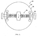
- Figure 2 illustrates a recovery unit 100 according to an embodiment of the invention for recovering energy.
- the recovery unit 100 comprises a pontoon 102 which may have a longitudinal and substantially cylindrical shape, for instance. Its cross section may be substantially circular or the pontoon 102 may be of any shape suitable for use in a recovery unit 100.
- the recovery unit also comprises a power transmission member 104, such as a longitudinal shaft, and an actuator 106 arranged inside the pontoon 102 casing 108.
- the actuator may further comprise a generator or a flywheel, for instance.
- the recovery unit may be used for collecting wave energy, for example, in which case the recovery unit is arranged in water either partially or substantially totally under the water surface or substantially above the water surface.
- Recovery units 100 may be connected in series with one or more other recovery units 100, which intensifies the wave energy collection. Waves generate a mutual movement between the pontoon 102 casing 108 and the actuator 106 inside the pontoon 102, and the movement is transmitted by the power transmission member 104 to the actuator 106 for recovery. The mutual movement may further be transmitted from the actuator 106 to one or more energy converters in connection with the recovery unit 100, which convert kinetic energy into another energy form, such as electric energy.
- each recovery unit 100 may comprise an energy converter of its own or more recovery units 100 may be connected to a common energy converter.
- the mutual movement between the pontoon 102 casing 108 and the actuator 106 is further converted into a unidirectional rotational movement in the movement converter.
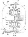
- FIGs 3a and 3b illustrate the principle of some movement converters 142, 144.
- the movement converter 142 illustrated in Figure 3a is arranged on rails 202 by rail wheels 146.
- the rail wheels 146 are fixed to their shaft irrotatably.
- Supporters 204 for supporting support wheels 206 are attached to the pontoon casing 108.
- the support wheels 206 are arranged to rotate on the rail 202 so that the support wheel 206 shown in Figure 3a is on the same side of the rail 202 as the rail wheel 146, whereas a support wheel 206 hidden behind the support wheel 206 shown in Figure 3a is on the other side of the rail 202.
- the support wheels 206 prevent the pontoon casing 108 from rotating with the rail wheel 146.
- the positioning, number and other similar details of the support wheels may naturally be implemented otherwise.
- support wheels 206 may be arranged in connection with both rails 202.
- the movement converter 144 is arranged on a toothed bar 208 by cog wheels 148.
- the power transmission member 104 of the pontoon 102 may be arranged to rotate the shafts 150, 152 included in the movement converters 142, 144 back and forth.
- the rotational movement of the shafts 150, 152 is transmitted to direction converting means 154, 156, 158, 160, which may include cog wheels 162, 164, 166, 168.
- the direction converting means 154 to 160 may include freewheel clutches 172 to 186.
- This kind of movement converter is disclosed, for instance, in Finnish Patent No. 112 694B , which is incorporated herein by reference.
- Generators 188, 190 convert the mechanical rotation movement into electric energy.
- a projection 210 preventing rotation is attached to the casing 108.
- the projection slides on the back of the toothed bar 208 as the pontoon 102 moves along the toothed bar 208.
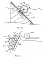
- Figures 4a, 4b , 4c and 4d illustrate recovery units according to embodiments of the invention for recovering energy from waves and for utilizing the tidal influence.
- the pontoon 102 is arranged to move with respect to the control surface 112 so that it simultaneously rotates about its shaft 110 due to the influence of waves or wind, for example.
- the control surface 112 may comprise a toothed rail 114 and the outer surface of the pontoon 102 a toothed rim 116 compatible with the toothed rail 114.
- the control surface 112 may further be an inclined surface in accordance with Figure 4a , whose angle of inclination ⁇ may be adjustable.
- the control surface 112 may also be a planar surface or the surface may be of any shape allowing the pontoon 102 to move.
- a mutual movement is generated between the pontoon 102 casing 108 and the actuator 106 as the pontoon 102 moves with respect to the control surface 112.
- the movement of the casing 108 is transmitted to rotate the actuator by power transmission means known per se.
- the control surface 112 returns the pontoon 102 to its initial position.
- the rotation of the power transmission members and the actuator with the pontoon 102 is prevented by an auxiliary body 212 attached to the shaft 110 and by support wheels 206 provided in the auxiliary body.
- the support wheels 206 are arranged to rotate on the bottom surface of a conductor 214 parallel with the control surface 112.
- the recovery unit 100 comprises a support arm 118 to which the pontoon 102 is attached.
- the pontoon 102 casing 108 is made to move with respect to the shaft 110 included in the pontoon 102, in which case mutual movement that may be recovered is generated between the pontoon 102 casing 108 and the shaft 110.
- control surface 112 may freely incline at angles of different sizes with respect to its attachment point.
- the control surface 112 may further preferably rotate about a vertical rotation axis so that the control surface 112 and the pontoon 102 may turn in the direction of the wave movement.
- the attachment point is at the bottom of a water system but it may naturally be placed elsewhere, for example above the water surface.
- the rotation of the power transmission members and the actuator with the pontoon 102 is prevented by an auxiliary body 212 attached to the shaft 110 and a support wheel 206 rotating at the back surface of the control surface 112.
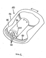
- Figure 5 illustrates a recovery unit 100 according to an embodiment of the invention, the recovery unit comprising a pontoon 102 whose outer surface may be provided with one or more wheels 120.
- a control surface 112 comprising at least one counter surface 124 is arranged in connection with the recovery unit 100. If necessary, the control surface 112 may be very long, for example in the order of one kilometre or even longer.
- the wheels 120 are compatible with the counter surfaces 124.
- the pontoon 102 casing 108 is made to move with respect to the wheels 120 and against the inclined control surface112 by means of wind, for example, in which case mutual movement is generated between the pontoon 102 casing 108 and the wheels 120.
- a planar surface 126 may be arranged in connection with the pontoon 102.
- the surface functions like a sail in wind facilitating in the vertical position, for example, the rising of the recovery unit 100 upwards against the control surface 112.
- the sail is in the forward position as the pontoon 102 returns to its initial position.
- the position of the planar surface 126 may be adjusted to the current wind conditions.
- FIG. 6 illustrates a recovery unit 100 according to an embodiment of the invention where power transmission members, which in this case include wheels 128, have been arranged inside the pontoon 102 casing 108.
- the wheels 128 are compatible with the counter surface 130 inside the pontoon 102 casing 108, and the actuator 106 and the power transmission members move freely parallel with the circumference of the casing 108 due to the influence of waves, for example.
- the recovery unit 100 is preferably anchored by cables or chains to the bottom of the water system, to an attachment point above the water surface, or to an attachment point below the water surface.
- the anchoring is most preferably implemented so that the recovery unit 100 may assume a most advantageous position in relation to the wave or wind direction and in respect of energy recovery.
- the power transmission members include a gear system 200 for changing the transmission ratio between the wheels 128 and the actuator 106.
- the gear system is a device known per se comprising at least means for producing two different transmission ratios between the wheels and the energy converter.
- the transmission ratios may be fixed transmission ratios with suitable transmission ratio differences, but preferably the transmission ratio is arranged to be adjusted steplessly by a variator, for example.
- the selection of the gear system's transmission ratio is preferably controlled according to the movement of the pontoon casing 108 and the rotation speed or resistance of an energy converter connected to the actuator 106, such as an electric generator.
- the transmission ratio is selected to be slow so that a relatively small force is sufficient for rotating the energy converter - even though at a slow speed.
- the transmission ratio is selected to be faster, in which case the rotation speed of the energy converter increases in relation to the rotation speed of the wheels 128.
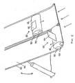
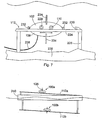
- FIG. 7 illustrates a recovery unit according to an embodiment of the invention.
- the recovery unit comprises a hollow pontoon 102. Inside the casing 108 of the pontoon, there is provided an actuator for recovering energy as described in connection with the previous figures.
- the actuator is connected to a shaft 110, whose rotation movement is transmitted to the actuator which is arranged to rotate an electric generator.
- the pontoon 102 is arranged to move under water and back and forth along rails 224 arranged substantially in the horizontal direction.
- the rails 224 form a control surface 112 of the pontoon.
- the pontoon 102 comprises rail wheels which rotate on the rails 224.
- the pontoon 102 comprises another pair of rail wheels 228 which supports the pontoon 102 on the rails 224.
- the rails 224 have been arranged in parallel at a distance from each other and supported close to the bottom 238 of the water system by supports 226.
- a buffer 230 is arranged at the end of the rails 224 to stop the pontoon 102 movement in this direction.
- the other end 224 of the rails is not illustrated in the figure.
- the pontoon 102 is provided with protecting buffers 232 which protect the pontoon when it hits the buffer 230. It should be noted that the buffers 232 are by no means necessary.
- the pontoon 102 moves along the rails 224 by the force of water movements.
- the pontoon 102 is provided with wings or sails 234 to intensify the pontoon 102 movement with water movements.
- the linear movement of the pontoon 102 rotates the shaft 110 and the actuator connected thereto and further the electric generator or another similar device which converts rotation energy into another energy form.
- the actuator converts the to-and-fro rotational movement of the shaft 110 into a unidirectional rotational movement as described above.
- the electric energy produced by the electric generator is transmitted further by a conductor 236, for instance. Since the pontoon 102 operates deep in the vicinity of the bottom 238, it is well protected from storms and ice.
- the other end 224 of the rails may be led to the shore, in which case the pontoon 102 may be pulled along the rails 224 to the dry land for maintenance or to protect it from a storm. In that case, any buffer at the other end of the rails 224 may be moved aside so that it is not in the way of the pontoon 102. In an embodiment of the invention, there is not buffer at all at the other end of the rails 224, but the pontoon 102 movement is restricted in a suitable manner by ascending rails 224. In a third embodiment, the both ends of the rails 224 are arranged to ascend in an appropriate manner, in which case the increasing potential energy of the pontoon 102 stops its movement.
- control surface 112 is arranged in an inclined position and the pontoon 102 moves, forced by the water movement, upwards along the surface.
- the pontoon 102 moves along the control surface 112 towards the lowest point of the control surface 112.
- the rotational movement of the shaft which preferably takes place in both directions, is utilized in producing energy.
- the principles of this embodiment are thus similar to those of the embodiment illustrated in Figure 5 .
- One or both of the rails 224 may be replaced with a toothed bar and the respective rails wheels with cog wheels.
- the pontoon 102 may be provided with means, such as brushes or the like, for cleaning the rail and/or toothed bar in front of the rail wheels and/or cog wheels.
- the recovery unit may be connected to any energy recovery unit, such as a wind power generator.
- Figure 8 illustrates a recovery unit according to an embodiment of the invention.
- This comprises a floating and movable raft 240, whose upper surface is provided with a first control surface 112a and the lower surface with a second control surface 12b.
- a first recovery unit 100a moves on the first control surface 112a.
- the recovery unit moves upwards along the inclined control, surface by the wind force and returns towards the lowest point of the control surface when wind slows down sufficiently or when the planar surface 126 is turned away from the wind.
- a second recovery unit 100b moves on the second control surface 11b.
- the recovery unit moves upwards along the inclined control surface by the force of water movement and returns towards the lowest point of the control surface when the water movement slows down sufficiently.
- the raft 240 may naturally also be implemented so that it comprises only one or more first control surfaces 112a and recovery units 100a, or only one or more second control surfaces 112b and recovery units 100b.
- the inclination of the control surfaces 112a, 112b is preferably adjustable.
- the raft 240 may be attached to the shore or to the bottom of the water system. The attachment is preferably implemented so as to allow the raft 240 to turn freely in the direction of the wind and/or the water movement.
- the recovery unit may be provided with means for placing the pontoon and its contents deeper than its normal depth of operation in the water system. This allows protecting the pontoon from storms and ice, for instance.
- the means may be based on the fact that the buoyant force of the pontoon can be decreased by letting water inside it and by pumping it out of the pontoon when the recovery unit is raised to its optimal depth for energy recovery.
- the pontoon may also be pulled deeper into the water system by engine power, in which case the buoyant force caused by the pontoon is overcome by engine power.
- the recovery unit may also be provided with a control system of the pontoon displacement for keeping the pontoon continuously at the optimal depth in a water system regardless of variations in density due to temperature changes or the like.
- the displacement control system comprises sensors for measuring the pontoon position with respect to the water surface or for measuring water density.
- the control unit of the control system determines whether an adjustment is necessary and controls actuators that let water into a control tank in the pontoon or remove water from the tank so that the pontoon's buoyant force is appropriate.
- the unidirectional rotational movement generated by the actuator 106 may be transmitted to a hydraulic pump, which converts the rotational movement into pressure of a fluid medium.
- the hydraulic pump is also preferably arranged inside the pontoon casing 108.
- the pontoon 102 may include both an electric generator and a hydraulic pump which are rotated either by one and the same actuator 106 or alternatively the electric generator is rotated by one actuator and the hydraulic pump by another actuator.
Landscapes
- Engineering & Computer Science (AREA)
- Chemical & Material Sciences (AREA)
- Combustion & Propulsion (AREA)
- Mechanical Engineering (AREA)
- General Engineering & Computer Science (AREA)
- Other Liquid Machine Or Engine Such As Wave Power Use (AREA)
- Wind Motors (AREA)
- Fire-Extinguishing Compositions (AREA)
- Paper (AREA)
- Physical Or Chemical Processes And Apparatus (AREA)
Claims (15)
- Verfahren zur Rückgewinnung von Energie, wobei das Verfahren umfasst:Rückgewinnen von Energie mittels mindestens einer Rückgewinnungseinheit (100), was umfasst:mindestens einen Ponton (102),mindestens ein Kraftübertragungsglied (104) undmindestens ein Stellglied (106);Erzeugen einer gegenseitigen Bewegung zwischen dem Ponton (102) und dem Stellglied (106);Übertragen der gegenseitigen Bewegung zwischen dem Ponton (102) und dem Stellglied (106) an das Stellglied (106) mittels mindestens eines Kraftübertragungsglieds (104);Rückgewinnen der gegenseitigen Bewegung des Pontons (102) und des Stellglieds (106) mittels des Stellglieds (106);Erzeugen einer gegenseitigen Bewegung zwischen dem Gehäuse (108) des Pontons (102) und dem Stellglied (106) innerhalb des Pontons (102); undÜbertragen der Bewegung mittels mindestens eines Kraftübertragungsglieds (104) an das Stellglied (106), um die Bewegung rückzugewinnen;Einrichten des Pontons (102), sich in Bezug auf die Steueroberfläche (112) zu bewegen, so dass die gegenseitige Bewegung zwischen dem Gehäuse (108) des Pontons (102) und dem Stellglied (106) erzeugt wird;Einrichten der Steueroberfläche (112), den Ponton (102) zu seiner Ausgangsstellung zurückzuführen, gekennzeichnet durchAnordnen des Stellglieds (106) innerhalb des Gehäuses (108) des Pontons (102) undRotieren eines elektrischen Generators mittels des Stellglieds (106), wobei der elektrische Generator innerhalb des Gehäuses (108) des Pontons (012) angeordnet ist.
- Verfahren gemäß Anspruch 1, gekennzeichnet durch Anordnen des Pontons (102), um mittels Wellen in Wasser bewegt zu werden.
- Verfahren gemäß Anspruch 2, gekennzeichnet durch Anordnen des Pontons (102) im Wesentlichen vollständig unter der Wasseroberfläche.
- Verfahren gemäß einem der vorhergehenden Ansprüche, gekennzeichnet durch Umwandeln der gegenseitigen Bewegung zwischen dem Ponton (102) und dem Stellglied (106) in eine unidirektionale Rotationsbewegung.
- Rückgewinnungseinheit zum Rückgewinnen von Energie, umfassend:mindestens einen Ponton (102),mindestens ein Kraftübertragungsglied (104); undmindestens ein Stellglied (106); undwobei das Kraftübertragungsglied (104) in der Rückgewinnungseinheit (100) dafür eingerichtet ist, eine gegenseitige Bewegung zwischen dem Ponton (102) und dem Stellglied (106) an das Stellglied (106) zu übertragen; undwobei das Stellglied (106) in der Rückgewinnungseinheit (100) dafür eingerichtet ist, die gegenseitige Bewegung zwischen dem Ponton (102) und dem Stellglied (106) rückzugewinnen;eine gegenseitige Bewegung, die zwischen dem Gehäuse (108) des Pontons (102) und dem Stellglied (106) innerhalb des Pontons (102) erzeugt wird, wobei das Kraftübertragungsglied (104) dafür eingerichtet ist, die Bewegung an das Stellglied (106) zu übertragen, das dafür eingerichtet ist, sie rückzugewinnen;wobei der Ponton (102) dafür eingerichtet ist, sich mit Bezug auf die Steueroberfläche (112) zu bewegen, so dass die gegenseitige Bewegung zwischen dem Gehäuse (108) des Pontons (102) und dem Stellglied (106) erzeugt wird;wobei die Steueroberfläche (112) dafür eingerichtet ist, den Ponton (102) zu seiner Ausgangsstellung zurückzuführen, dadurch gekennzeichnet, dassdas Stellglied (106) innerhalb des Gehäuses (108) des Pontons (102) angeordnet ist; undeinen innerhalb des Gehäuses (108) des Pontons (102) angeordneten elektrischen Generator, wobei das Stellglied dafür eingerichtet ist, den elektrischen Generator zu rotieren.
- Rückgewinnungseinheit gemäß Anspruch 5, dadurch gekennzeichnet, dass eine Steueroberfläche (112) in Verbindung mit der Rückgewinnungseinheit (100) angeordnet ist, wobei die Steueroberfläche ein Zahnschiene (114) umfasst; und dass das Kraftübertragungsglied (104) ein Kammrad (148) umfasst, das in Kontakt mit der Zahnschiene (114) angeordnet ist, wobei eine Zahnleiste (116), die mit der Zahnschiene (114), die auf der Steueroberfläche angeordnet ist, auf der Außenfläche des Pontons (102) angeordnet ist.
- Rückgewinnungseinheit gemäß Anspruch 5, dadurch gekennzeichnet, dass eine Steueroberfläche (112), die eine Gegenoberfläche (124) umfasst, in Verbindung mit der Rückgewinnungseinheit (100) angeordnet ist; und der Ponton mit mindestens einem Rad (120) ausgestattet ist, das mit der Gegenoberfläche (124), die auf der Steueroberfläche (112) angeordnet ist, kompatibel ist.
- Rückgewinnungseinheit gemäß den Ansprüchen 6 oder 7, dadurch gekennzeichnet, dass die Steueroberfläche (112) eine geneigte Oberfläche ist, deren Neigungswinkel einstellbar ist.
- Rückgewinnungseinheit gemäß Anspruch 5, dadurch gekennzeichnet, dass das Kraftübertragungsglied (104) innerhalb des Gehäuses (108) des Pontons (102) angeordnet ist; und das Stellglied (106) und das Kraftübertragungsglied (104) dafür eingerichtet sind, sich frei in Richtung des Umfangs des Gehäuses (108) entlang einer Gegenoberfläche (130), die innerhalb des Pontons (102) angeordnet ist, zu bewegen.
- Rückgewinnungseinheit gemäß einem der Ansprüche 5 bis 9,
dadurch gekennzeichnet, dass das Stellglied (106) ein Bewegungswandler (142) ist, der dafür eingerichtet ist, die Bewegung zwischen dem Ponton (102) und dem Stellglied (106) in eine unidirektionale Rotationsbewegung umzuwandeln. - Rückgewinnungseinheit gemäß einem der Ansprüche 5 bis 10,
dadurch gekennzeichnet, dass die Rückgewinnungseinheit (100) mit mindestens einer anderen Rückgewinnungseinheit (100) seriell verbunden ist, um einen energierückgewinnenden Wellenbrecher zu bilden. - Rückgewinnungseinheit gemäß einem der Ansprüche 5 bis 11,
dadurch gekennzeichnet, dass die Rückgewinnungseinheit (100) mit einem Windkraftgenerator verbunden ist. - Rückgewinnungseinheit gemäß einem der Ansprüche 5 bis 12,
dadurch gekennzeichnet, dass die Kraftübertragungsglieder (104) ein Getriebesystem (200) umfassen, das dafür eingerichtet ist, mindestens zwei unterschiedliche Übertragungsverhältnisse für die Bewegung zwischen dem Pontongehäuse (108) und dem Stellglied (106) hervorzubringen. - Rückgewinnungseinheit gemäß einem der Ansprüche 5 bis 13,
dadurch gekennzeichnet, dass sie in einem Floß (240) angeordnet ist. - Rückgewinnungseinheit zum Rückgewinnen von Energie, die Rückgewinnungseinheit umfassend: mindestens einen Ponton (102), mindestens ein Kraftübertragungsglied (104) und mindestens ein Stellglied (106); und wobei das Kraftübertragungsglied (104) in der Rückgewinnungseinheit (100) dafür eingerichtet ist, eine gegenseitige Bewegung zwischen dem Ponton (102) und dem Stellglied (106) an das Stellglied (106) zu übertragen; und wobei das Stellglied (106) in der Rückgewinnungseinheit (100) dafür eingerichtet ist, die gegenseitige Bewegung zwischen dem Ponton (102) und dem Stellglied (106) rückzugewinnen, wobei eine gegenseitige Bewegung zwischen dem Pontongehäuse (108) und dem Stellglied (106) innerhalb des Pontons (102) erzeugt wird, wobei das Kraftübertragungsglied (104) dafür eingerichtet ist, die Bewegung an das Stellglied (106) zu übertragen, das dafür eingerichtet ist, sie rückzugewinnen, dadurch gekennzeichnet, dass mindestens ein Teil der Länge des Pontons (102) dafür eingerichtet ist, sich auf einer Steueroberfläche (112), die in einer horizontalen Richtung angeordnet ist, zu bewegen, so dass eine gegenseitige Bewegung zwischen dem Gehäuse (108) des Pontons (102) und dem Stellglied (106) erzeugt wird;
wobei das Stellglied (106) innerhalb des Gehäuses (108) des Pontons (102) angeordnet ist; und
ein elektrischer Generator innerhalb des Gehäuses (108) des Pontons (102) angeordnet ist, wobei das Stellglied dafür eingerichtet ist, den elektrischen Generator zu rotieren.
Applications Claiming Priority (2)
| Application Number | Priority Date | Filing Date | Title |
|---|---|---|---|
| FI20065237A FI20065237A0 (fi) | 2006-04-18 | 2006-04-18 | Järjestely energian talteen ottamiseksi |
| PCT/FI2007/050197 WO2007118936A1 (en) | 2006-04-18 | 2007-04-16 | Arrangement for recovering energy |
Publications (3)
| Publication Number | Publication Date |
|---|---|
| EP2007980A1 EP2007980A1 (de) | 2008-12-31 |
| EP2007980A4 EP2007980A4 (de) | 2013-04-17 |
| EP2007980B1 true EP2007980B1 (de) | 2014-06-11 |
Family
ID=36293830
Family Applications (1)
| Application Number | Title | Priority Date | Filing Date |
|---|---|---|---|
| EP07730684.3A Not-in-force EP2007980B1 (de) | 2006-04-18 | 2007-04-16 | Anordnung zur rückgewinnung von energie |
Country Status (7)
| Country | Link |
|---|---|
| EP (1) | EP2007980B1 (de) |
| CN (1) | CN101479468B (de) |
| AU (1) | AU2007239447B2 (de) |
| CA (1) | CA2649139C (de) |
| FI (1) | FI20065237A0 (de) |
| NO (1) | NO339755B1 (de) |
| WO (1) | WO2007118936A1 (de) |
Families Citing this family (3)
| Publication number | Priority date | Publication date | Assignee | Title |
|---|---|---|---|---|
| EP2466118A1 (de) * | 2010-12-15 | 2012-06-20 | Fundacion Inasmet | Leistungsaufnahmevorrichtung zur Wellenenergieumwandlung |
| CN103122820B (zh) * | 2011-11-17 | 2015-04-15 | 四川蓝讯宝迩电子科技有限公司 | 列车式双浮筒海浪发电装置 |
| EP4705627A1 (de) * | 2023-05-04 | 2026-03-11 | SwellGen Limited | Vorrichtung zur energieerzeugung aus einer welle |
Family Cites Families (10)
| Publication number | Priority date | Publication date | Assignee | Title |
|---|---|---|---|---|
| DE119310C (de) * | ||||
| US1379183A (en) * | 1920-05-17 | 1921-05-24 | Harris Rex | Wave-motor |
| US2179537A (en) * | 1938-04-11 | 1939-11-14 | Arthur E Zoppa | Self-energizing sea water processing plant |
| GB628422A (en) * | 1947-08-27 | 1949-08-29 | Herbert Heaton Patrick | Improvements in wave or tide motors |
| NO145353C (no) * | 1974-07-04 | 1982-03-03 | Kjell Budal | Konstruksjon for omforming av boelgeenergi til annan energi |
| DE4423454A1 (de) * | 1994-07-05 | 1996-02-01 | Cramer Friedrich | Wasserwellenkraftnutzer auf bewegten Gewässern |
| DE19610922A1 (de) * | 1996-03-20 | 1998-01-15 | Carl Jung | Energieerzeugung aus bewegtem Wasser |
| DE19612124C2 (de) * | 1996-03-27 | 2003-03-27 | Manfred Dyck | Vorrichtung zur Umwandlung von in Wasserwellenbewegungen enthaltener Energie in nutzbare Energie |
| JP2004176621A (ja) * | 2002-11-27 | 2004-06-24 | Michihiro Oe | 波力発電方法および波力発電装置 |
| CN2784607Y (zh) * | 2005-01-21 | 2006-05-31 | 张建民 | 水力转换风力发电装置 |
-
2006
- 2006-04-18 FI FI20065237A patent/FI20065237A0/fi not_active Application Discontinuation
-
2007
- 2007-04-16 WO PCT/FI2007/050197 patent/WO2007118936A1/en not_active Ceased
- 2007-04-16 CA CA2649139A patent/CA2649139C/en not_active Expired - Fee Related
- 2007-04-16 CN CN2007800226311A patent/CN101479468B/zh not_active Expired - Fee Related
- 2007-04-16 AU AU2007239447A patent/AU2007239447B2/en not_active Ceased
- 2007-04-16 EP EP07730684.3A patent/EP2007980B1/de not_active Not-in-force
-
2008
- 2008-11-14 NO NO20084812A patent/NO339755B1/no not_active IP Right Cessation
Also Published As
| Publication number | Publication date |
|---|---|
| CA2649139A1 (en) | 2007-10-25 |
| WO2007118936A1 (en) | 2007-10-25 |
| CN101479468A (zh) | 2009-07-08 |
| EP2007980A1 (de) | 2008-12-31 |
| NO20084812L (no) | 2009-01-15 |
| NO339755B1 (no) | 2017-01-30 |
| EP2007980A4 (de) | 2013-04-17 |
| CN101479468B (zh) | 2011-05-18 |
| CA2649139C (en) | 2015-03-31 |
| AU2007239447A1 (en) | 2007-10-25 |
| AU2007239447B2 (en) | 2012-02-16 |
| FI20065237A0 (fi) | 2006-04-18 |
Similar Documents
| Publication | Publication Date | Title |
|---|---|---|
| US11591999B2 (en) | System for conversion of wave energy into electrical energy | |
| US9127640B2 (en) | Multi-capture mode wave energy converter with submergible float | |
| US10094356B2 (en) | Multi mode wave energy converter with elongated wave front parallel float having integral lower shoaling extension | |
| US9863395B2 (en) | Wave energy converter with concurrent multi-directional energy absorption | |
| AU2014233070B2 (en) | Wave energy converter system | |
| EP2659128B1 (de) | Energieerzeugungsverfahren und -vorrichtung | |
| CN101611226B (zh) | 能量提取方法和设备 | |
| US10989164B2 (en) | Resonant unidirectional wave energy converter | |
| CN101802390A (zh) | 用于将波浪能转换为电能的系统及方法 | |
| WO2011057420A2 (es) | Dispositivo propulsor o motor para transformar energía en potencia, utilizando las fuerzas producidas con el movimiento superficial de un líquido o fluido o lo similar | |
| EP3368719B1 (de) | Mit mitteln zur rückgewinnung von energie aus wellenbewegung ausgestattete küstenschutzinfrastruktur | |
| WO2017062528A2 (en) | Multi mode wave energy converter with elongated wave front parallel float having integral lower shoaling extension | |
| EP2007980B1 (de) | Anordnung zur rückgewinnung von energie | |
| CA2847346A1 (en) | Submergible sloped absorption barrier wave energy converter | |
| CN117386549A (zh) | 波浪能发电装置及风力水力结合式发电机 | |
| KR20260044040A (ko) | 수영 훈련용 조류 발생 장치 | |
| WO2024069550A1 (en) | Wave energy converter | |
| WO2011138749A1 (en) | Plant for the exploitation of marine or river currents for the production of electricity |
Legal Events
| Date | Code | Title | Description |
|---|---|---|---|
| PUAI | Public reference made under article 153(3) epc to a published international application that has entered the european phase |
Free format text: ORIGINAL CODE: 0009012 |
|
| 17P | Request for examination filed |
Effective date: 20081023 |
|
| AK | Designated contracting states |
Kind code of ref document: A1 Designated state(s): AT BE BG CH CY CZ DE DK EE ES FI FR GB GR HU IE IS IT LI LT LU LV MC MT NL PL PT RO SE SI SK TR |
|
| AX | Request for extension of the european patent |
Extension state: AL BA HR MK RS |
|
| DAX | Request for extension of the european patent (deleted) | ||
| A4 | Supplementary search report drawn up and despatched |
Effective date: 20130320 |
|
| RIC1 | Information provided on ipc code assigned before grant |
Ipc: F03B 13/16 20060101AFI20130314BHEP Ipc: F03D 5/04 20060101ALI20130314BHEP Ipc: F03B 13/18 20060101ALI20130314BHEP |
|
| 17Q | First examination report despatched |
Effective date: 20130415 |
|
| GRAP | Despatch of communication of intention to grant a patent |
Free format text: ORIGINAL CODE: EPIDOSNIGR1 |
|
| INTG | Intention to grant announced |
Effective date: 20140120 |
|
| GRAS | Grant fee paid |
Free format text: ORIGINAL CODE: EPIDOSNIGR3 |
|
| GRAA | (expected) grant |
Free format text: ORIGINAL CODE: 0009210 |
|
| AK | Designated contracting states |
Kind code of ref document: B1 Designated state(s): AT BE BG CH CY CZ DE DK EE ES FI FR GB GR HU IE IS IT LI LT LU LV MC MT NL PL PT RO SE SI SK TR |
|
| REG | Reference to a national code |
Ref country code: GB Ref legal event code: FG4D |
|
| REG | Reference to a national code |
Ref country code: CH Ref legal event code: EP |
|
| REG | Reference to a national code |
Ref country code: IE Ref legal event code: FG4D |
|
| REG | Reference to a national code |
Ref country code: AT Ref legal event code: REF Ref document number: 672392 Country of ref document: AT Kind code of ref document: T Effective date: 20140715 |
|
| REG | Reference to a national code |
Ref country code: DE Ref legal event code: R096 Ref document number: 602007037106 Country of ref document: DE Effective date: 20140724 |
|
| PG25 | Lapsed in a contracting state [announced via postgrant information from national office to epo] |
Ref country code: GR Free format text: LAPSE BECAUSE OF FAILURE TO SUBMIT A TRANSLATION OF THE DESCRIPTION OR TO PAY THE FEE WITHIN THE PRESCRIBED TIME-LIMIT Effective date: 20140912 Ref country code: LT Free format text: LAPSE BECAUSE OF FAILURE TO SUBMIT A TRANSLATION OF THE DESCRIPTION OR TO PAY THE FEE WITHIN THE PRESCRIBED TIME-LIMIT Effective date: 20140611 Ref country code: FI Free format text: LAPSE BECAUSE OF FAILURE TO SUBMIT A TRANSLATION OF THE DESCRIPTION OR TO PAY THE FEE WITHIN THE PRESCRIBED TIME-LIMIT Effective date: 20140611 |
|
| REG | Reference to a national code |
Ref country code: NL Ref legal event code: VDEP Effective date: 20140611 |
|
| REG | Reference to a national code |
Ref country code: AT Ref legal event code: MK05 Ref document number: 672392 Country of ref document: AT Kind code of ref document: T Effective date: 20140611 |
|
| REG | Reference to a national code |
Ref country code: LT Ref legal event code: MG4D |
|
| PG25 | Lapsed in a contracting state [announced via postgrant information from national office to epo] |
Ref country code: SE Free format text: LAPSE BECAUSE OF FAILURE TO SUBMIT A TRANSLATION OF THE DESCRIPTION OR TO PAY THE FEE WITHIN THE PRESCRIBED TIME-LIMIT Effective date: 20140611 Ref country code: LV Free format text: LAPSE BECAUSE OF FAILURE TO SUBMIT A TRANSLATION OF THE DESCRIPTION OR TO PAY THE FEE WITHIN THE PRESCRIBED TIME-LIMIT Effective date: 20140611 |
|
| PG25 | Lapsed in a contracting state [announced via postgrant information from national office to epo] |
Ref country code: CZ Free format text: LAPSE BECAUSE OF FAILURE TO SUBMIT A TRANSLATION OF THE DESCRIPTION OR TO PAY THE FEE WITHIN THE PRESCRIBED TIME-LIMIT Effective date: 20140611 Ref country code: ES Free format text: LAPSE BECAUSE OF FAILURE TO SUBMIT A TRANSLATION OF THE DESCRIPTION OR TO PAY THE FEE WITHIN THE PRESCRIBED TIME-LIMIT Effective date: 20140611 Ref country code: SK Free format text: LAPSE BECAUSE OF FAILURE TO SUBMIT A TRANSLATION OF THE DESCRIPTION OR TO PAY THE FEE WITHIN THE PRESCRIBED TIME-LIMIT Effective date: 20140611 Ref country code: RO Free format text: LAPSE BECAUSE OF FAILURE TO SUBMIT A TRANSLATION OF THE DESCRIPTION OR TO PAY THE FEE WITHIN THE PRESCRIBED TIME-LIMIT Effective date: 20140611 Ref country code: EE Free format text: LAPSE BECAUSE OF FAILURE TO SUBMIT A TRANSLATION OF THE DESCRIPTION OR TO PAY THE FEE WITHIN THE PRESCRIBED TIME-LIMIT Effective date: 20140611 Ref country code: PT Free format text: LAPSE BECAUSE OF FAILURE TO SUBMIT A TRANSLATION OF THE DESCRIPTION OR TO PAY THE FEE WITHIN THE PRESCRIBED TIME-LIMIT Effective date: 20141013 |
|
| PG25 | Lapsed in a contracting state [announced via postgrant information from national office to epo] |
Ref country code: AT Free format text: LAPSE BECAUSE OF FAILURE TO SUBMIT A TRANSLATION OF THE DESCRIPTION OR TO PAY THE FEE WITHIN THE PRESCRIBED TIME-LIMIT Effective date: 20140611 Ref country code: NL Free format text: LAPSE BECAUSE OF FAILURE TO SUBMIT A TRANSLATION OF THE DESCRIPTION OR TO PAY THE FEE WITHIN THE PRESCRIBED TIME-LIMIT Effective date: 20140611 Ref country code: IS Free format text: LAPSE BECAUSE OF FAILURE TO SUBMIT A TRANSLATION OF THE DESCRIPTION OR TO PAY THE FEE WITHIN THE PRESCRIBED TIME-LIMIT Effective date: 20141011 Ref country code: PL Free format text: LAPSE BECAUSE OF FAILURE TO SUBMIT A TRANSLATION OF THE DESCRIPTION OR TO PAY THE FEE WITHIN THE PRESCRIBED TIME-LIMIT Effective date: 20140611 |
|
| REG | Reference to a national code |
Ref country code: DE Ref legal event code: R097 Ref document number: 602007037106 Country of ref document: DE |
|
| PLBE | No opposition filed within time limit |
Free format text: ORIGINAL CODE: 0009261 |
|
| STAA | Information on the status of an ep patent application or granted ep patent |
Free format text: STATUS: NO OPPOSITION FILED WITHIN TIME LIMIT |
|
| PG25 | Lapsed in a contracting state [announced via postgrant information from national office to epo] |
Ref country code: IT Free format text: LAPSE BECAUSE OF FAILURE TO SUBMIT A TRANSLATION OF THE DESCRIPTION OR TO PAY THE FEE WITHIN THE PRESCRIBED TIME-LIMIT Effective date: 20140611 Ref country code: DK Free format text: LAPSE BECAUSE OF FAILURE TO SUBMIT A TRANSLATION OF THE DESCRIPTION OR TO PAY THE FEE WITHIN THE PRESCRIBED TIME-LIMIT Effective date: 20140611 |
|
| 26N | No opposition filed |
Effective date: 20150312 |
|
| REG | Reference to a national code |
Ref country code: DE Ref legal event code: R097 Ref document number: 602007037106 Country of ref document: DE Effective date: 20150312 |
|
| PG25 | Lapsed in a contracting state [announced via postgrant information from national office to epo] |
Ref country code: BE Free format text: LAPSE BECAUSE OF FAILURE TO SUBMIT A TRANSLATION OF THE DESCRIPTION OR TO PAY THE FEE WITHIN THE PRESCRIBED TIME-LIMIT Effective date: 20140611 |
|
| PG25 | Lapsed in a contracting state [announced via postgrant information from national office to epo] |
Ref country code: SI Free format text: LAPSE BECAUSE OF FAILURE TO SUBMIT A TRANSLATION OF THE DESCRIPTION OR TO PAY THE FEE WITHIN THE PRESCRIBED TIME-LIMIT Effective date: 20140611 |
|
| PG25 | Lapsed in a contracting state [announced via postgrant information from national office to epo] |
Ref country code: MC Free format text: LAPSE BECAUSE OF FAILURE TO SUBMIT A TRANSLATION OF THE DESCRIPTION OR TO PAY THE FEE WITHIN THE PRESCRIBED TIME-LIMIT Effective date: 20140611 Ref country code: LU Free format text: LAPSE BECAUSE OF FAILURE TO SUBMIT A TRANSLATION OF THE DESCRIPTION OR TO PAY THE FEE WITHIN THE PRESCRIBED TIME-LIMIT Effective date: 20150416 |
|
| REG | Reference to a national code |
Ref country code: CH Ref legal event code: PL |
|
| PG25 | Lapsed in a contracting state [announced via postgrant information from national office to epo] |
Ref country code: LI Free format text: LAPSE BECAUSE OF NON-PAYMENT OF DUE FEES Effective date: 20150430 Ref country code: CH Free format text: LAPSE BECAUSE OF NON-PAYMENT OF DUE FEES Effective date: 20150430 |
|
| REG | Reference to a national code |
Ref country code: FR Ref legal event code: PLFP Year of fee payment: 10 |
|
| PG25 | Lapsed in a contracting state [announced via postgrant information from national office to epo] |
Ref country code: MT Free format text: LAPSE BECAUSE OF FAILURE TO SUBMIT A TRANSLATION OF THE DESCRIPTION OR TO PAY THE FEE WITHIN THE PRESCRIBED TIME-LIMIT Effective date: 20140611 |
|
| REG | Reference to a national code |
Ref country code: FR Ref legal event code: PLFP Year of fee payment: 11 |
|
| PG25 | Lapsed in a contracting state [announced via postgrant information from national office to epo] |
Ref country code: BG Free format text: LAPSE BECAUSE OF FAILURE TO SUBMIT A TRANSLATION OF THE DESCRIPTION OR TO PAY THE FEE WITHIN THE PRESCRIBED TIME-LIMIT Effective date: 20140611 Ref country code: HU Free format text: LAPSE BECAUSE OF FAILURE TO SUBMIT A TRANSLATION OF THE DESCRIPTION OR TO PAY THE FEE WITHIN THE PRESCRIBED TIME-LIMIT; INVALID AB INITIO Effective date: 20070416 |
|
| PG25 | Lapsed in a contracting state [announced via postgrant information from national office to epo] |
Ref country code: CY Free format text: LAPSE BECAUSE OF FAILURE TO SUBMIT A TRANSLATION OF THE DESCRIPTION OR TO PAY THE FEE WITHIN THE PRESCRIBED TIME-LIMIT Effective date: 20140611 |
|
| PGFP | Annual fee paid to national office [announced via postgrant information from national office to epo] |
Ref country code: GB Payment date: 20170420 Year of fee payment: 11 Ref country code: DE Payment date: 20170412 Year of fee payment: 11 Ref country code: FR Payment date: 20170412 Year of fee payment: 11 Ref country code: IE Payment date: 20170419 Year of fee payment: 11 |
|
| PG25 | Lapsed in a contracting state [announced via postgrant information from national office to epo] |
Ref country code: TR Free format text: LAPSE BECAUSE OF FAILURE TO SUBMIT A TRANSLATION OF THE DESCRIPTION OR TO PAY THE FEE WITHIN THE PRESCRIBED TIME-LIMIT Effective date: 20140611 |
|
| REG | Reference to a national code |
Ref country code: DE Ref legal event code: R119 Ref document number: 602007037106 Country of ref document: DE |
|
| GBPC | Gb: european patent ceased through non-payment of renewal fee |
Effective date: 20180416 |
|
| REG | Reference to a national code |
Ref country code: IE Ref legal event code: MM4A |
|
| PG25 | Lapsed in a contracting state [announced via postgrant information from national office to epo] |
Ref country code: DE Free format text: LAPSE BECAUSE OF NON-PAYMENT OF DUE FEES Effective date: 20181101 |
|
| PG25 | Lapsed in a contracting state [announced via postgrant information from national office to epo] |
Ref country code: GB Free format text: LAPSE BECAUSE OF NON-PAYMENT OF DUE FEES Effective date: 20180416 |
|
| PG25 | Lapsed in a contracting state [announced via postgrant information from national office to epo] |
Ref country code: IE Free format text: LAPSE BECAUSE OF NON-PAYMENT OF DUE FEES Effective date: 20180416 Ref country code: FR Free format text: LAPSE BECAUSE OF NON-PAYMENT OF DUE FEES Effective date: 20180430 |