EP2008012B1 - Steckverbinder für insbesondere aus kunststoff bestehende rohrleitungen - Google Patents
Steckverbinder für insbesondere aus kunststoff bestehende rohrleitungen Download PDFInfo
- Publication number
- EP2008012B1 EP2008012B1 EP07728088A EP07728088A EP2008012B1 EP 2008012 B1 EP2008012 B1 EP 2008012B1 EP 07728088 A EP07728088 A EP 07728088A EP 07728088 A EP07728088 A EP 07728088A EP 2008012 B1 EP2008012 B1 EP 2008012B1
- Authority
- EP
- European Patent Office
- Prior art keywords
- plug
- receiving
- attachment
- plug connector
- connector according
- Prior art date
- Legal status (The legal status is an assumption and is not a legal conclusion. Google has not performed a legal analysis and makes no representation as to the accuracy of the status listed.)
- Not-in-force
Links
- 239000004033 plastic Substances 0.000 title claims abstract description 12
- 229920003023 plastic Polymers 0.000 title claims abstract description 12
- 238000007789 sealing Methods 0.000 claims description 25
- 239000002184 metal Substances 0.000 claims description 4
- 229910001369 Brass Inorganic materials 0.000 claims description 3
- 239000010951 brass Substances 0.000 claims description 3
- 239000000463 material Substances 0.000 claims description 3
- 239000012530 fluid Substances 0.000 abstract 1
- 238000003780 insertion Methods 0.000 description 11
- 230000037431 insertion Effects 0.000 description 11
- 239000004952 Polyamide Substances 0.000 description 1
- 238000001746 injection moulding Methods 0.000 description 1
- 230000014759 maintenance of location Effects 0.000 description 1
- 238000000034 method Methods 0.000 description 1
- 239000002245 particle Substances 0.000 description 1
- 230000035515 penetration Effects 0.000 description 1
- 230000002093 peripheral effect Effects 0.000 description 1
- 229920002647 polyamide Polymers 0.000 description 1
- 238000000926 separation method Methods 0.000 description 1
- 239000000243 solution Substances 0.000 description 1
Images



Classifications
-
- F—MECHANICAL ENGINEERING; LIGHTING; HEATING; WEAPONS; BLASTING
- F16—ENGINEERING ELEMENTS AND UNITS; GENERAL MEASURES FOR PRODUCING AND MAINTAINING EFFECTIVE FUNCTIONING OF MACHINES OR INSTALLATIONS; THERMAL INSULATION IN GENERAL
- F16L—PIPES; JOINTS OR FITTINGS FOR PIPES; SUPPORTS FOR PIPES, CABLES OR PROTECTIVE TUBING; MEANS FOR THERMAL INSULATION IN GENERAL
- F16L37/00—Couplings of the quick-acting type
- F16L37/08—Couplings of the quick-acting type in which the connection between abutting or axially overlapping ends is maintained by locking members
- F16L37/084—Couplings of the quick-acting type in which the connection between abutting or axially overlapping ends is maintained by locking members combined with automatic locking
- F16L37/092—Couplings of the quick-acting type in which the connection between abutting or axially overlapping ends is maintained by locking members combined with automatic locking by means of elements wedged between the pipe and the frusto-conical surface of the body of the connector
- F16L37/0925—Couplings of the quick-acting type in which the connection between abutting or axially overlapping ends is maintained by locking members combined with automatic locking by means of elements wedged between the pipe and the frusto-conical surface of the body of the connector with rings which bite into the wall of the pipe
-
- F—MECHANICAL ENGINEERING; LIGHTING; HEATING; WEAPONS; BLASTING
- F16—ENGINEERING ELEMENTS AND UNITS; GENERAL MEASURES FOR PRODUCING AND MAINTAINING EFFECTIVE FUNCTIONING OF MACHINES OR INSTALLATIONS; THERMAL INSULATION IN GENERAL
- F16L—PIPES; JOINTS OR FITTINGS FOR PIPES; SUPPORTS FOR PIPES, CABLES OR PROTECTIVE TUBING; MEANS FOR THERMAL INSULATION IN GENERAL
- F16L33/00—Arrangements for connecting hoses to rigid members; Rigid hose-connectors, i.e. single members engaging both hoses
- F16L33/22—Arrangements for connecting hoses to rigid members; Rigid hose-connectors, i.e. single members engaging both hoses with means not mentioned in the preceding groups for gripping the hose between inner and outer parts
- F16L33/227—Arrangements for connecting hoses to rigid members; Rigid hose-connectors, i.e. single members engaging both hoses with means not mentioned in the preceding groups for gripping the hose between inner and outer parts the hose being introduced into or onto the connecting member and automatically locked
-
- F—MECHANICAL ENGINEERING; LIGHTING; HEATING; WEAPONS; BLASTING
- F16—ENGINEERING ELEMENTS AND UNITS; GENERAL MEASURES FOR PRODUCING AND MAINTAINING EFFECTIVE FUNCTIONING OF MACHINES OR INSTALLATIONS; THERMAL INSULATION IN GENERAL
- F16L—PIPES; JOINTS OR FITTINGS FOR PIPES; SUPPORTS FOR PIPES, CABLES OR PROTECTIVE TUBING; MEANS FOR THERMAL INSULATION IN GENERAL
- F16L37/00—Couplings of the quick-acting type
- F16L37/08—Couplings of the quick-acting type in which the connection between abutting or axially overlapping ends is maintained by locking members
- F16L37/084—Couplings of the quick-acting type in which the connection between abutting or axially overlapping ends is maintained by locking members combined with automatic locking
- F16L37/092—Couplings of the quick-acting type in which the connection between abutting or axially overlapping ends is maintained by locking members combined with automatic locking by means of elements wedged between the pipe and the frusto-conical surface of the body of the connector
- F16L37/0926—Couplings of the quick-acting type in which the connection between abutting or axially overlapping ends is maintained by locking members combined with automatic locking by means of elements wedged between the pipe and the frusto-conical surface of the body of the connector with an inner support sleeve arranged within the pipe
-
- F—MECHANICAL ENGINEERING; LIGHTING; HEATING; WEAPONS; BLASTING
- F16—ENGINEERING ELEMENTS AND UNITS; GENERAL MEASURES FOR PRODUCING AND MAINTAINING EFFECTIVE FUNCTIONING OF MACHINES OR INSTALLATIONS; THERMAL INSULATION IN GENERAL
- F16L—PIPES; JOINTS OR FITTINGS FOR PIPES; SUPPORTS FOR PIPES, CABLES OR PROTECTIVE TUBING; MEANS FOR THERMAL INSULATION IN GENERAL
- F16L37/00—Couplings of the quick-acting type
- F16L37/08—Couplings of the quick-acting type in which the connection between abutting or axially overlapping ends is maintained by locking members
- F16L37/084—Couplings of the quick-acting type in which the connection between abutting or axially overlapping ends is maintained by locking members combined with automatic locking
- F16L37/092—Couplings of the quick-acting type in which the connection between abutting or axially overlapping ends is maintained by locking members combined with automatic locking by means of elements wedged between the pipe and the frusto-conical surface of the body of the connector
- F16L37/0927—Couplings of the quick-acting type in which the connection between abutting or axially overlapping ends is maintained by locking members combined with automatic locking by means of elements wedged between the pipe and the frusto-conical surface of the body of the connector the wedge element being axially displaceable for releasing the coupling
-
- F—MECHANICAL ENGINEERING; LIGHTING; HEATING; WEAPONS; BLASTING
- F16—ENGINEERING ELEMENTS AND UNITS; GENERAL MEASURES FOR PRODUCING AND MAINTAINING EFFECTIVE FUNCTIONING OF MACHINES OR INSTALLATIONS; THERMAL INSULATION IN GENERAL
- F16L—PIPES; JOINTS OR FITTINGS FOR PIPES; SUPPORTS FOR PIPES, CABLES OR PROTECTIVE TUBING; MEANS FOR THERMAL INSULATION IN GENERAL
- F16L2201/00—Special arrangements for pipe couplings
- F16L2201/30—Detecting leaks
-
- F—MECHANICAL ENGINEERING; LIGHTING; HEATING; WEAPONS; BLASTING
- F16—ENGINEERING ELEMENTS AND UNITS; GENERAL MEASURES FOR PRODUCING AND MAINTAINING EFFECTIVE FUNCTIONING OF MACHINES OR INSTALLATIONS; THERMAL INSULATION IN GENERAL
- F16L—PIPES; JOINTS OR FITTINGS FOR PIPES; SUPPORTS FOR PIPES, CABLES OR PROTECTIVE TUBING; MEANS FOR THERMAL INSULATION IN GENERAL
- F16L2201/00—Special arrangements for pipe couplings
- F16L2201/80—Dust covers
Definitions
- the present invention relates to a connector according to the preamble of claim 1.
- the EP 0 733 844 B1 describes a connecting device for quick and detachable connection of at least one plastic pipe, consisting of a housing part with at least one receiving opening for insertion of the pipe and from a receiving opening arranged in the clamping ring, which cooperates for locking the pipe via an outer cone with an inner cone of the housing part ,
- the housing part for the purpose of solvability of the pipe in two parts consists of a base part and a releasably connected thereto, the inner cone having insert and the insert is connected via a snap-fit connection with the base part.
- the insert part has an inner, circumferential sealing lip for sealing contact with the outer peripheral surface of the pipeline, the sealing lip extending obliquely inwards in the direction of insertion prior to insertion of the pipeline so that it is somewhat elastically widened by the inserted pipeline and then sealingly abuts.
- the EP 0 753 698 B1 describes a connector for connecting pressure medium lines, consisting of a housing part with a one-sided opening having receptacle for inserting a particular formed by a pipe end plug portion, wherein within the receptacle on the side facing the opening at least one holding element and starting from the holding element in the direction of at least one sealing element is arranged away from the opening, and a holding function is additionally ensured during the insertion process of the plug-in section into the receptacle of the housing part and in addition the sealing element seals off the plug-in section relative to the housing part, the housing part having a leakage path in such a way that in a locked by the retaining element, but not yet sealed on the sealing element insertion position of the plug-in section a defined limited, noticeable leak ge is guaranteed.
- the leakage path is associated with a valve element such that in the not yet sealed via the sealing element insertion position of the plug section on the one hand, the pressure medium on the leakage path can escape to the outside, but on the other hand, penetration of dirt particles and the like excluded from the outside into the housing interior is.
- the DE 203 19 959 U1 describes a connector for media lines, consisting of a housing part with a plug-in receptacle for media-tight insertion of a pipe-shaped plug, wherein in the plug receptacle a retaining element for locking and a media seal for sealing the inserted plug are arranged, and wherein the housing part in two parts of a base part and with a consists of this connected via a snap-fit positive connection insert.
- the base part itself in turn in two parts from a receiving part for the holding element, the media seal and the insert part and a connection part for connecting the housing part to a media line.
- U1 also claims a connector for media lines, which may have the above features, consisting of a housing part with a plug-in receptacle for media-tight insertion of a pipe-shaped plug, wherein seen within the socket from a muzzle-side dirt seal in the insertion direction first, a holding element for locking the inserted plug and on it Subsequently, a media seal are arranged, wherein a leakage path is formed such that in a locked by the retaining element, but not yet sealed over the media seal Vorarretier ein the male a defined limited, physically perceptible leakage is ensured.
- the leakage path is formed by depressions arranged on the outer circumference of the insertion part, which are arranged in the pre-locking position on the one hand in the region of the media seal and on the other hand in the region of the dirt seal.
- two-part designs with a reduced metal content are also used.
- two-part, connectors usually pre-assembled plastic-receiving parts with retaining element and sealing ring are attached to screw-in, as the DE 203 19 959 U1 can be seen.
- These known connectors follow the basic principle: "hold before densities".
- the disadvantage of this connector is that in addition to the main sealing ring, which seals the tube against the receiving part, another sealing ring must seal the receiving part against the screw. On the one hand, this causes high costs, and on the other hand creates a place where leaks can occur.
- the present invention has for its object to provide a multi-part connector of the generic type, which has a simplified assembly capability with high reliability.
- the media seal is arranged to seal the inserted plug between the connection part and the pipe-piece plug is advantageously achieved that except the main sealing ring formed by the media seal, which seals the tube against the receiving part, no further sealing ring the receiving part against the Screw part must seal.
- the connector according to the invention which all have in common that the media seal, in particular a sealing ring, on the pipe connection side, the only interface to the pressurized space within the connector.
- the housing part 2 has a base part 10, which consists of a receiving part 16 for the holding element 6 in two parts and from a, in particular designed as a screw, connection part 14 for connection connection of the housing part 2 to a threaded bore of an arbitrary unit, not shown.
- a support sleeve 12 is preferably arranged for supporting engagement in the male part to be inserted.
- the media seal 8 is arranged radially between the connecting part 14 and the tubular piece-shaped plug-in part for sealing the plug-in part inserted in the plug-in receptacle 4. This eliminates a pressure seal in the region of the receiving part 16 and also an additional seal between the connecting part 14 and the receiving part 16.
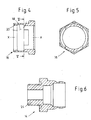
- Fig. 1 to 3 show now that the receiving part 16 is formed as a part of the connecting part 14 sleeve-like surrounding cuff part, which is preferably clipped onto the connecting part 14 and consists of plastic.
- the cuff part 16 is in 4 and 5 shown as a single part.
- a designated by the reference numeral 18, in Fig. 4 By a circular arc circumscribed latching area of the sleeve part 16 is so elastic that when clipping no damage. In this case, it is also possible to provide the sleeve part in the latching region with an axial slit (executed parallel to the longitudinal axis XX).
- the media seal 8 in particular an O-ring, in the connection part 14, which may in particular consist of brass and in one embodiment as a screw-in in Fig. 6 is shown as a single part.
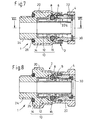
- a plastic receiving part sleeve part 16 may include a polygonal, in particular hexagonal, outer contour of the connecting part 14 with a sleeve portion 20 on the outside and thus form a rotation.
- the sleeve part 16 can be regarded as part of the housing part 2.
- the plastic may advantageously comprise in particular only two key surfaces of the connecting part 14, which have undersize.
- the rotation can also be achieved by knurling on one or both of the components 16 or 14, if the area between these parts is designed as a press fit. This can also be achieved by a pressing area without knurling.
- a friction torque occurring during a rotation for setting the angular positions should advantageously assume values of more than 10 Nm.
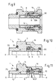
- the sleeve part 16 can also be fastened in another way to the connection part 14, for example by screwing on. It is also possible to construct the sleeve part 16, which surrounds the connection part 14, as a screw-on part made of plastic (KST) or brass (Ms), as shown in FIG Fig. 9 is shown, or otherwise unlocked as this Fig. 10 shows. Accordingly, then also gives the design of the connection part 14 of the in Fig. 6 shown off.
- KST plastic
- Ms brass
- a dirt seal 30 need not be molded in a multi-component injection molding process, but can simply be inserted as a sealing ring in an inner annular groove of the insert part 22.
- FIGS. 12 and 13 shown further embodiment of the invention has a great similarity to that in Fig. 8 illustrated embodiment.
- the characteristic of this execution consists - like in Fig. 13 shown enlarged view shows that in order to increase the strength of the connection between the connecting part 14 of the base part 10 of the housing 2 and the receiving part 16 on the circumference of the connecting part 14 force-locking elements 40 are arranged.
- These elements 40 which are impressed into the inner wall 42 of the receiving part 16, may have a different shape, but in the illustrated embodiment advantageously have a sawtooth shape, so that the connecting part is designed for pressing with the receiving part 16 in the manner of a wrapping mandrel ,
- the force-fit elements 40 can be circulated or distributed over the entire or only over part of the circumference.
- the encompassed contour of the connecting part 14 is designated by the reference numeral 44.
- the characteristic feature of this embodiment is that the contour 44 encompassed by the receiving part is present in addition to a contour 46 of the connecting part 14 that exists in accordance with the standard and serves to attack a tool key. Due to this separation of the contours 44, 46, very high tightening torques of the key can advantageously be transmitted to the connection part 14 during assembly or disassembly without damage.
- the invention is not limited to the illustrated embodiments, but also includes embodiments, as already clear by the different illustrated structural embodiments of the various components. With regard to these possible equivalent embodiments of the components, in particular to the documents mentioned above EP 0 753 698 B1 . EP 0 733 844 B1 and DE 203 19 959 U1 in full and in particular to the above corresponding remarks.
- a connecting portion 24 of the connecting part 14 may be formed as a screw threaded connection, wherein an additional sealing ring 26, in particular as an axial seal, is provided.
Landscapes
- Engineering & Computer Science (AREA)
- General Engineering & Computer Science (AREA)
- Mechanical Engineering (AREA)
- Quick-Acting Or Multi-Walled Pipe Joints (AREA)
- Valve Housings (AREA)
- Shaping Of Tube Ends By Bending Or Straightening (AREA)
Description
- Die vorliegende Erfindung betrifft einen Steckverbinder gemäß dem Oberbegriff des Anspruchs 1.
- Im Zusammenhang mit solchen Steckverbindern sind beispielsweise die
DE 10261595 A1 , dieEP 0 753 698 B1 , dieEP 0 733 844 B1 und dieDE 203 19 959 U1 als Stand der Technik von Bedeutung, in denen verschiedene Anwendungen und konstruktive Ausführungen von derartigen oder ähnlichen bekannten Anschlussvorrichtungen beschrieben werden. - Die
EP 0 733 844 B1 beschreibt dabei eine Anschlussvorrichtung zum schnellen und lösbaren Anschluss mindestens einer Kunststoff-Rohrleitung, bestehend aus einem Gehäuseteil mit mindestens einer Aufnahmeöffnung zum Einstecken der Rohrleitung sowie aus einem in der Aufnahmeöffnung angeordneten Klemmring, der zum Arretieren der Rohrleitung über einen Außenkonus mit einem Innenkonus des Gehäuseteils zusammenwirkt, wobei das Gehäuseteil zwecks Lösbarkeit der Rohrleitung zweiteilig aus einem Basisteil und einem lösbar mit diesem verbundenen, den Innenkonus aufweisenden Einsatzteil besteht und das Einsatzteil über eine schnappbare Formschlussverbindung mit dem Basisteil verbunden ist. Hierbei ist vorgesehen, dass das Einsatzteil eine innere, umlaufende Dichtlippe zur dichtenden Anlage auf der Außenumfangsfläche der Rohrleitung aufweist, wobei die Dichtlippe sich vor dem Einstecken der Rohrleitung derart in Einsteckrichtung schräg nach innen erstreckt, dass sie durch die eingesteckte Rohrleitung etwas elastisch aufgeweitet wird und dann dichtend anliegt. - Die
EP 0 753 698 B1 beschreibt eine Steckverbindung zum Anschluss von Druckmittelleitungen, bestehend aus einem Gehäuseteil mit einer eine einseitige Öffnung aufweisenden Aufnahme zum Einstecken eines insbesondere von einem Rohrleitungsende gebildeten Steckabschnittes, wobei innerhalb der Aufnahme auf der der Öffnung zugekehrten Seite mindestens ein Halteelement und von dem Halteelement ausgehend in Richtung von der Öffnung weg mindestens ein Dichtungselement angeordnet ist, und beim Einsteckvorgang des Steckabschnittes in die Aufnahme des Gehäuseteils zuerst eine Haltefunktion und im weiteren Verkauf des Einsteckvorganges zusätzlich über das Dichtungselement eine Abdichtung des Steckabschnittes gegenüber dem Gehäuseteil gewährleistet ist, wobei das Gehäuseteil einen Leckagepfad derart aufweist, dass in einer durch das Halteelement arretierten, jedoch noch nicht über das Dichtungselement abgedichteten Einsteckstellung des Steckabschnittes eine definiert begrenzte, wahrnehmbare Undichtigkeit gewährleistet ist. Hierbei ist vorgesehen, dass dem Leckagepfad ein Ventilelement derart zugeordnet ist, dass in der noch nicht über das Dichtungselement abgedichteten Einsteckstellung des Steckabschnittes einerseits das Druckmittel über den Leckagepfad nach außen treten kann, andererseits aber ein Eindringen von Schmutzpartikeln und dergleichen von außen in das Gehäuseinnere ausgeschlossen ist. - Die
DE 203 19 959 U1 beschreibt einen Steckverbinder für Medienleitungen, bestehend aus einem Gehäuseteil mit einer Steckaufnahme zum mediendichten Einstecken eines rohrstückförmigen Einsteckteils, wobei in der Steckaufnahme ein Halteelement zum Arretieren sowie eine Mediendichtung zum Abdichten des eingesteckten Einsteckteils angeordnet sind, und wobei das Gehäuseteil zweiteilig aus einem Basisteil und einem mit diesem über eine schnappbare Formschlussverbindung verbundenen Einsatzteil besteht. Hierbei ist vorgesehen, dass das Basisteil seinerseits ebenfalls zweiteilig aus einem Aufnahmeteil für das Halteelement, die Mediendichtung und das Einsatzteil sowie aus einem Anschlussteil zur Anschlussverbindung des Gehäuseteils an eine Medienleitung besteht. - Gleichzeitig wird in der
DE 203 19 959 U1 auch ein Steckverbinder für Medienleitungen beansprucht, der die vorstehenden Merkmale aufweisen kann, bestehend aus einem Gehäuseteil mit einer Steckaufnahme zum mediendichten Einstecken eines rohrstückförmigen Einsteckteils, wobei innerhalb der Steckaufnahme ausgehend von einer mündungsseitigen Schmutzdichtung in Einsteckrichtung gesehen zunächst ein Halteelement zum Arretieren des eingesteckten Einsteckteils und daran anschließend eine Mediendichtung angeordnet sind, wobei ein Leckagepfad derart gebildet ist, dass in einer durch das Halteelement arretierten, aber noch nicht über die Mediendichtung abgedichteten Vorarretierstellung des Einsteckteils eine definiert begrenzte, physisch wahrnehmbare Undichtigkeit gewährleistet ist. Hierbei ist vorgesehen, dass der Leckagepfad durch auf dem Außenumfang des Einsteckteils angeordnete Vertiefungen gebildet ist, die in der Vorarretierstellung einerseits im Bereich der Mediendichtung und andererseits im Bereich der Schmutzdichtung angeordnet sind. - Bei heute eingesetzten, einteiligen, Stutzen ähnlicher Art (
EP 0 753 698 B1 ,EP 0 733 844 B1 ) werden üblicherweise Aufnahmeteile mit Halteelement und Dichtring in einen Metall-Einschraubstutzen eingesetzt. Der Nachteil bei diesen Steckverbindungen ist dabei, dass der Anteil an Metall sehr groß ist und daher auch die Kosten für Material und Bearbeitung entsprechend hoch sind. - Es werden daher auch zweiteilige Ausführungen mit reduziertem Metall-Anteil eingesetzt. Bei diesen, zweiteiligen, Steckverbindungen werden üblicherweise vormontierte Kunststoff-Aufnahmeteile mit Halteelement und Dichtring an Einschraubteilen befestigt, wie dies der
DE 203 19 959 U1 zu entnehmen ist. Diese bekannten Steckverbindungen folgen dabei dem Grundprinzip: "Halten vor Dichten". Der Nachteil dieser Steckverbinder ist, dass außer dem Haupt-Dichtring, der das Rohr gegen das Aufnahmeteil abdichtet, ein weiterer Dichtring das Aufnahmeteil gegen das Einschraubteil dichten muss. Das verursacht einerseits hohe Kosten, und andererseits entsteht eine Stelle, an der Undichtigkeiten auftreten können. - Der vorliegenden Erfindung liegt die Aufgabe zugrunde, einen mehrteiligen Steckverbinder der gattungsgemäßen Art zu schaffen, der bei hoher Funktionssicherheit eine vereinfachte Montagefähigkeit aufweist.
- Als gattungsgemäß wird dabei ein Steckverbinder angesehen, wie er in der
DE 203 19 959 U1 , insbesondere in der inFig. 6 dargestellten Ausführungsform, beschrieben ist. - Erfindungsgemäß wird dies durch die Merkmale des kennzeichnenden Teiles des Anspruchs 1 erreicht.
- Dadurch, dass die Mediendichtung zum Abdichten des eingesteckten Einsteckteils zwischen dem Anschlussteil und dem rohrstückförmigen Einsteckteil angeordnet ist, wird vorteilhafterweise erreicht, dass außer dem durch die Mediendichtung gebildeten Haupt-Dichtring, der das Rohr gegen das Aufnahmeteil abdichtet, kein weiterer Dichtring das Aufnahmeteil gegen das Einschraubteil dichten muss. Dabei sind für den erfindungsgemäßen Steckverbinder verschiedene technische Detaillösungen möglich, denen allen gemeinsam ist, dass die Mediendichtung, insbesondere ein Dichtring, auf der Rohr-Anschlußseite, die einzige Schnittstelle zum druckbeaufschlagten Raum innerhalb der Steckverbindung ist.
- Weitere vorteilhafte Ausgestaltungsmerkmale der Erfindung sind in den Unteransprüchen sowie der folgenden Beschreibung enthalten.
- Anhand mehrerer bevorzugter Ausführungsbeispiele soll im Folgenden die Erfindung näher erläutert werden. Dabei zeigen:
- Fig. 1
- eine perspektivische Gesamtansicht eines erfindungsgemäßen Steckverbinders,
- Fig. 2
- einen Längsschnitt durch den in
Fig. 1 dargestellten erfindungsgemäßen Steckverbinder, - Fig. 3
- einen weiteren Längsschnitt durch den in
Fig. 1 dargestellten erfindungsgemäßen Steckverbinder, entlang der Linie III-III inFig. 2 , - Fig. 4
- einen Längsschnitt durch ein dem erfindungsgemäßen Steckverbinder zugeordnetes Bauteil,
- Fig. 5
- einen Querschnitt durch das in
Fig. 4 dargestellte Bauteil, entlang der Linie V-V inFig. 4 , - Fig. 6
- einen Längsschnitt durch ein weiteres dem erfindungsgemäßen Steckverbinder zugeordnetes Bauteil,
- Fig. 7
- eine Darstellung eines Längsschnitts einer weiteren Ausführung eines erfindungsgemäßen Steckverbinders,
- Fig. 8
- einen weiteren Längsschnitt durch den in
Fig. 7 dargestellten erfindungsgemäßen Steckverbinder, entlang der Linie VIII-VIII inFig. 7 , - Fig. 9
- eine Ansicht analog zu
Fig. 3 und8 in einer Ausführungsvariante, - Fig. 10
- einen Steckverbinder, der nicht in den Rahmen der Erfindung fällt
- Fig. 11
- einen Längsschnit einer weiteren Ausführungsform eines erfindungsgemäßen Steckverbinders
- Fig. 12
- einen Querschnitt durch eine weitere Ausführungsform der Erfindung,
- Fig. 13
- eine vergrößerte Darstellung der in
Fig. 12 mit B bezeichneten Einzelheit, - Fig. 14
- die Darstellung einer halbgeschnittenen weiteren Ausführungsform der Erfindung,
- Fig. 15
- das Anschlussteil der in
Fig. 14 dargestellten Ausführung. - In den verschiedenen Figuren der Zeichnung sind gleiche Teile stets mit den gleichen Bezugszeichen versehen und werden daher im Folgenden in der Regel jeweils nur einmal beschrieben.
- Wie sich zunächst aus
Fig. 1 bis 3 ergibt, besteht ein erfindungsgemäßer Steckverbinder 1 für insbesondere aus Kunststoff bestehende Rohrleitungen aus einem Gehäuseteil 2 mit einer Steckaufnahme 4 zum mediendichten Einstecken eines rohrstückförmigen (nicht dargestellten) insbesondere aus Kunststoff, wie Polyamid, bestehenden Einsteckteils, wie eines Rohrendes, wobei in der Steckaufnahme 4 ein Halteelement 6 zum Arretieren sowie eine Mediendichtung 8 zum Abdichten des eingesteckten Einsteckteils angeordnet sind. Dabei weist das Gehäuseteil 2 ein Basisteil 10 auf, welches zweiteilig aus einem Aufnahmeteil 16 für das Halteelement 6 sowie aus einem, insbesondere als Einschraubstutzen ausgebildeten, Anschlussteil 14 zur Anschlussverbindung des Gehäuseteils 2 an eine Gewindebohrung eines nicht dargestellten, beliebigen Aggregates besteht. Innerhalb des Gehäuseteils 2 ist vorzugsweise eine Stützhülse 12 zum stützenden Eingriff in das einzusteckende Einsteckteil angeordnet. - Die Mediendichtung ist 8 zum Abdichten des in die Steckaufnahme 4 eingesteckten Einsteckteils radial zwischen dem Anschlussteil 14 und dem rohrstückförmigen Einsteckteil angeordnet. Dadurch erübrigt sich eine Druckdichtung im Bereich des Aufnahmeteils 16 sowie auch eine zusätzliche Dichtung zwischen Anschlussteil 14 und Aufnahmeteil 16.
-
Fig. 1 bis 3 zeigen nun, dass das Aufnahmeteil 16 als ein das Anschlussteil 14 bereichsweise hülsenartig umgebendes Manschettenteil ausgebildet ist, das vorzugsweise auf das Anschlussteil 14 aufclipsbar ist und aus Kunststoff besteht. Das Manschettenteil 16 ist inFig. 4 und 5 als Einzelteil dargestellt. Ein mit dem Bezugszeichen 18 bezeichneter, inFig. 4 durch einen Kreisbogen umschriebener Rastbereich des Manschettenteils 16 ist dabei derart elastisch, dass beim Aufclipsen keine Beschädigungen entstehen. Hierbei ist es auch möglich, das Manschettenteil im Rastbereich mit einer axialen (parallel zur Längsachse X-X ausgeführten) Schlitzung zu versehen. - Wie erwähnt, liegt im Einbauzustand die Mediendichtung 8, insbesondere ein O-Ring, in dem Anschlussteil 14, das insbesondere aus Messing bestehen kann und in einer Ausführung als Einschraubstutzen in
Fig. 6 als Einzelteil dargestellt ist. - Wie
Fig. 7 und 8 zeigen, kann das als Kunststoff-Aufnahmeteil ausgebildete Manschettenteil 16 eine polygonale, insbesondere sechskantige, Außenkontur des Anschlussteils 14 mit einem Muffenabschnitt 20 außenseitig umfassen und so eine Verdrehsicherung bilden. Insofern kann das Manschettenteil 16 als Bestandteil des Gehäuseteils 2 angesehen werden. Der Kunststoff kann dabei mit Vorteil insbesondere nur zwei Schlüsselflächen des Anschlussteils 14 umfassen, die Untermaß haben. Die Verdrehsicherung kann auch durch eine Rändelung an einem oder beiden der Bauteile 16 oder 14 erreicht werden, wenn der Bereich zwischen diesen Teilen als Presspassung ausgelegt ist. Auch durch einen Pressbereich ohne Rändelung kann dies erreicht werden. Ein bei einer Drehung zum Einstellen der Winkelpositionen auftretendes Reibmoment sollte vorteilhafterweise bevorzugt Werte von mehr als 10 Nm annehmen. - Das Manschettenteil 16 kann auch auf andere Art am Anschlussteil 14 befestigt sein, beispielsweise durch Aufschrauben. Es ist auch möglich, das Manschettenteil 16, welches das Anschlussteil 14 umgibt, als aufschraubbares, aus Kunststoff (KST) oder Messing (Ms) bestehendes Teil auszuführen, wie dies in
Fig. 9 dargestellt ist, oder in anderer Weise aufzurasten, wie diesFig. 10 zeigt. Entsprechend weicht dann auch die Gestaltung des Anschlussteils 14 von der inFig. 6 gezeigten ab. - Wie in
Fig. 9 veranschaulicht ist, ist es durch die Zweiteiligkeit des aus dem Anschlussteil 14 und dem Aufnahmeteil 16 bestehenden Basisteils 10 möglich, das Einsatzteil 22 "von innen her" einzusetzen, wobei eine formschlüssige Halterung erreicht wird. Es erübrigt sich daher auch eine Verrastung, so dass das Einsatzteil 22 als starres, relativ unelastisches Ringelement ausgebildet sein kann. Deshalb muss eine Schmutzdichtung 30 nicht in einem Mehrkomponenten-Spritzverfahren angeformt werden, sondern kann einfach als Dichtring in eine innere Ringnut des Einsatzteils 22 eingelegt werden. - Die in
Fig. 12 und 13 dargestellte weitere Ausführungsform der Erfindung weist eine große Ähnlichkeit zu der inFig. 8 dargestellten Ausführung auf. Das Charakteristikum dieser Ausführung besteht - wie die inFig. 13 gezeigte vergrößerte Darstellung zeigt - darin, dass zur Erhöhung der Festigkeit der Verbindung zwischen dem Anschlussteil 14 des Basisteils 10 des Gehäuses 2 und dem Aufnahmeteil 16 auf dem Umfang des Anschlussteils 14 Kraft-Formschluss-Elemente 40 angeordnet sind. Diese Elemente 40, die sich in die Innenwand 42 des Aufnahmeteils 16 einprägen, können eine verschiedenartige Gestalt haben, weisen aber in der dargestellten Ausführung vorteilhafterweise eine Sägezahnform auf, so dass das Anschlussteil für eine Verpressung mit dem Aufnahmeteil 16 nach der Art eines Einschlagdorns ausgebildet ist. Die Kraft-Formschluss-Elemente 40 können über den gesamten oder auch nur über einen Teil des Umfangs umlaufen bzw. verteilt sein. - Bei der in
Fig. 14 und 15 dargestellten Ausführungsform der Erfindung umfasst das Aufnahmeteil 16 außenseitig - wie auch inFig. 7 und 8 gezeigt - formschlüssig eine polygonale, insbesondere sechskantige, Außenkontur des Anschlussteils 14 mit einem Muffenabschnitt 20, so dass die beiden Teile 14, 16 gegeneinander gegen eine Verdrehung gesichert sind. Die umfasste Kontur des Anschlussteils 14 ist mit dem Bezugszeichen 44 bezeichnet. Hierbei besteht das Charakteristikum dieser Ausführung darin, dass die vom Aufnahmeteil umfasste Kontur 44 zusätzlich zu einer normgemäß vorhandenen Kontur 46 des Anschlussteils 14 vorhanden ist, die dem Angriff eines Werkzeugschlüssels dient. Durch diese Trennung der Konturen 44, 46 können bei der Montage bzw. Demontage vorteilhafterweise beschädigungsfrei sehr hohe Anzugsmomente des Schlüssels auf das Anschlussteil 14 übertragen werden. - Die Erfindung ist nicht auf die dargestellten Ausführungsbeispiele beschränkt, sondern umfasst auch Ausführungen, wie dies bereits durch die unterschiedlichen dargestellten konstruktiven Ausführungsformen der verschiedenen Bauteile deutlich wird. Was diese möglichen gleichwirkenden Ausführungen der Bauteile betrifft, wird insbesondere auf die eingangs genannten Dokumente
EP 0 753 698 B1 ,EP 0 733 844 B1 undDE 203 19 959 U1 in vollem Umfang und im Speziellen auf obige entsprechende Ausführungen verwiesen. - So beschreibt beispielsweise die
DE 203 19 959 U1 ein Merkmal, das auch bei den dargestellten Ausführungen der Erfindung vorgesehen ist, nämlich dass ein Verbindungsabschnitt 24 des Anschlussteils 14 als Schraubgewindestutzen ausgebildet sein kann, wobei ein zusätzlicher Dichtring 26, insbesondere als Axialdichtung, vorgesehen ist. -
- 1
- Steckverbinder
- 2
- Gehäuseteil
- 4
- Steckaufnahme von 2
- 6
- Halteelement
- 8
- Mediendichtung
- 10
- Basisteil von 2
- 12
- Stützhülse
- 14
- Anschlussteil von 10
- 16
- Aufnahmeteil von 10 für 8
- 18
- Rastbereich von 16
- 20
- Muffenabschnitt von 16
- 22
- Einsatzteil von 2
- 22a
- Innenkonus
- 24
- Verbindungsabschnitt von 14
- 26
- zusätzliche Dichtung
- 30
- Schmutzdichtung
- 40
- Kraft-Formschluss-Element
- 42
- Innenwand von 16
- 44
- von 16 umgriffene Kontur von 14
- 46
- Kontur von 14 für Werkzeugangriff
- KST
- Kunststoff
- Ms
- Messing
- X-X
- Längsachse von 1
Claims (7)
- Steckverbinder (1) für insbesondere aus Kunststoff bestehende Rohrleitungen, bestehend aus einem Gehäuseteil (2) mit einer Steckaufnahme (4) zum mediendichten Einstecken eines rohrstückförmigen Einsteckteils, wobei in der Steckaufnahme (4) ein Halteelement (6) zum Arretieren sowie eine Mediendichtung (8) zum Abdichten des eingesteckten Einsteckteils angeordnet sind, und wobei das Gehäuseteil (2) ein Basisteil (10) aufweist, welches zweiteilig aus einem Aufnahmeteil (16) für das Halteelement (6) sowie aus einem Anschlussteil (14) zur Anschlussverbindung des Gehäuseteils (2), insbesondere an eine Gewindebohrung besteht, wobei die Mediendichtung (8) zum Abdichten des eingesteckten Einsteckteils radial zwischen dem Anschlussteil (14) und dem rohrstückförmigen Einsteckteil angeordnet ist, wobei das Gehäuseteil (2) aus dem Basisteil (10) und aus einem mit diesem verbundenen Einsatzteil (22) besteht.
dadurch gekennzeichnet, dass das Einsatzteil (22) formschlüssig im Inneren des Aufnahmeteils (16) gehalten ist, wobei das Aufnahmeteil (16) als ein das Anschlussteil (14) bereichsweise hülsenartig umgebendes Manschettenteil ausgebildet ist, und dass einerseits am Einsatzteil (22) über einen Innenkonus (22a) des Einsatzteiles (22) das Halteelement (6) radial abgestützt ist und andererseits in eine innere Ringnut des Einsatzteils (22) eine Schmutzdichtung (30) als Dichtring eingelegt ist. - Steckverbinder nach Anspruch 1,
dadurch gekennzeichnet, dass das Basisteil (10) und das Einsatzteil (22) über eine schnappbare Formschlussverbindung verbunden sind. - Steckverbinder nach Anspruch 1 oder 2,
dadurch gekennzeichnet, dass das Anschlussteil (14) aus Metall, vorzugsweise aus Messing (Ms), und das Aufnahmeteil (16) aus Kunststoff (KST) bestehen. - Steckverbinder nach einem der Ansprüche 1 bis 3,
dadurch gekennzeichnet, dass das Aufnahmeteil (16) durch Aufschrauben auf dem Anschlussteil (14) befestigt ist. - Steckverbinder nach einem der Ansprüche 1 bis 3,
dadurch gekennzeichnet, dass das Aufnahmeteil (16) mit dem Anschlussteil (14) verdrehfest verbunden, insbesondere verpresst, ist, wobei vorzugsweise das Aufnahmeteil (16) eine Außenkontur des Anschlussteils (14) formangepasst umfasst. - Steckverbinder nach Anspruch 5,
dadurch gekennzeichnet, dass die Außenkontur des Anschlussteils (14) polygonal oder gerändelt ausgebildet ist oder zwei Schlüsselflächen mit Untermaß aufweist. - Steckverbinder nach Anspruch 5,
dadurch gekennzeichnet, dass zur Erhöhung der Festigkeit der Verbindung zwischen dem Anschlussteil (14) des Basisteils (10) des Gehäuses (2) und dem Aufnahmeteil (16) auf dem Umfang des Anschlussteils (14) Kraft-Formschluss-Elemente (40) angeordnet sind, die sich in die Innenwand (42) des Aufnahmeteils (16) einprägen.
Applications Claiming Priority (2)
| Application Number | Priority Date | Filing Date | Title |
|---|---|---|---|
| DE202006006304U DE202006006304U1 (de) | 2006-04-18 | 2006-04-18 | Steckverbinder für insbesondere aus Kunststoff bestehende Rohrleitungen |
| PCT/EP2007/053623 WO2007118855A1 (de) | 2006-04-18 | 2007-04-13 | Steckverbinder für insbesondere aus kunststoff bestehende rohrleitungen |
Publications (2)
| Publication Number | Publication Date |
|---|---|
| EP2008012A1 EP2008012A1 (de) | 2008-12-31 |
| EP2008012B1 true EP2008012B1 (de) | 2009-09-23 |
Family
ID=38434733
Family Applications (1)
| Application Number | Title | Priority Date | Filing Date |
|---|---|---|---|
| EP07728088A Not-in-force EP2008012B1 (de) | 2006-04-18 | 2007-04-13 | Steckverbinder für insbesondere aus kunststoff bestehende rohrleitungen |
Country Status (6)
| Country | Link |
|---|---|
| US (1) | US20090102184A1 (de) |
| EP (1) | EP2008012B1 (de) |
| CN (1) | CN101427065B (de) |
| AT (1) | ATE443832T1 (de) |
| DE (2) | DE202006006304U1 (de) |
| WO (1) | WO2007118855A1 (de) |
Cited By (1)
| Publication number | Priority date | Publication date | Assignee | Title |
|---|---|---|---|---|
| DE102010031703A1 (de) * | 2010-07-21 | 2012-01-26 | Knorr-Bremse Systeme für Nutzfahrzeuge GmbH | Leitungsverbindungseinrichtung, Montageverfahren für eine Leitungsverbindungseinrichtung sowie Ventilgehäuse mit einer Leitungsverbindungseinrichtung |
Families Citing this family (8)
| Publication number | Priority date | Publication date | Assignee | Title |
|---|---|---|---|---|
| DE102010048226A1 (de) * | 2010-10-12 | 2012-04-12 | Veritas Ag | Verbindungsvorrichtung für zwei sich abschnittsweise überlappende Leitungen |
| US10302230B2 (en) | 2014-06-09 | 2019-05-28 | Eaton Intelligent Power Limited | Field serviceable conduit receivers |
| US9551445B2 (en) | 2014-06-09 | 2017-01-24 | Cooper Technologies Company | Conduit receivers |
| US10480698B2 (en) | 2014-09-19 | 2019-11-19 | Kongsberg Automotive As | Tube connector |
| CN105508779B (zh) * | 2016-01-20 | 2019-01-01 | 张男 | 管道的插接机构 |
| US10288202B2 (en) * | 2017-08-11 | 2019-05-14 | Cheng Yu Faucet Hardware Co., Ltd. | Installation between valve connector and pipe of ice maker |
| DE102020203751A1 (de) | 2020-03-24 | 2021-09-30 | Contitech Luftfedersysteme Gmbh | Luftanschluss einer Luftfeder |
| DE102020215372A1 (de) | 2020-12-04 | 2022-06-09 | Mahle International Gmbh | Verschlussstopfen für einen Sammler eines Kältemittelkreislaufs |
Family Cites Families (18)
| Publication number | Priority date | Publication date | Assignee | Title |
|---|---|---|---|---|
| US1896371A (en) * | 1929-06-27 | 1933-02-07 | Bundy Tubing Co | Tube and coupling |
| US2412664A (en) * | 1944-05-20 | 1946-12-17 | Parker Appliance Co | Coupling for tubes |
| US3210101A (en) * | 1963-05-10 | 1965-10-05 | Anaconda American Brass Co | Interlocking hose end fitting |
| FR2479406B1 (fr) * | 1980-03-28 | 1985-08-23 | Legris | Raccords instantanes pour tubes nus et lisses |
| SE455638B (sv) * | 1982-08-27 | 1988-07-25 | Ekman K R | Anordning vid en kopplingsenhet med forsta och andra mutterformade kopplingsdelar samt sett for framstellning av anordningen |
| GB2132296B (en) * | 1982-12-13 | 1986-02-05 | Guest John Ltd | Tube coupling |
| IN164968B (de) * | 1984-11-12 | 1989-07-15 | Guest John D | |
| DE3603721C2 (de) * | 1985-08-20 | 1994-11-17 | Smc Kk | Kupplung für Mehrfachdurchlaßleitung |
| JPH073119Y2 (ja) * | 1989-11-20 | 1995-01-30 | シーケーディ株式会社 | 管継手 |
| US5388866A (en) * | 1990-03-09 | 1995-02-14 | Lourdes Industries | High pressure coupling with provision for preventing separation of parts and with anti-galling provision |
| DE19510193A1 (de) * | 1995-03-21 | 1996-09-26 | Voss Armaturen | Anschlußvorrichtung für Rohrleitungen |
| DE19524934A1 (de) | 1995-07-08 | 1997-01-09 | Voss Armaturen | Steckverbindung zum Anschluß von Druckmittelleitungen |
| CN2317380Y (zh) * | 1997-10-14 | 1999-05-05 | 李学好 | 快速管接头组件 |
| DE29807763U1 (de) * | 1998-04-29 | 1999-09-09 | Armaturenfabrik Hermann Voss GmbH + Co, 51688 Wipperfürth | Anschlußvorrichtung zum schnellen und lösbaren Anschluß von Rohrleitungen |
| US6843507B2 (en) * | 2001-12-28 | 2005-01-18 | Smc Kabushiki Kaisha | Tube joint |
| GB0221076D0 (en) * | 2002-09-11 | 2002-10-23 | Guest John Int Ltd | Improvements in or relating to tube couplings |
| DE20214847U1 (de) * | 2002-09-24 | 2004-02-19 | Voss Automotive Gmbh | Anschlußvorrichtung für Rohrleitungen |
| DE20319959U1 (de) * | 2003-12-23 | 2005-05-04 | Voss Automotive Gmbh | Steckverbinder für Medienleitungen |
-
2006
- 2006-04-18 DE DE202006006304U patent/DE202006006304U1/de not_active Expired - Lifetime
-
2007
- 2007-04-13 AT AT07728088T patent/ATE443832T1/de active
- 2007-04-13 DE DE502007001588T patent/DE502007001588D1/de active Active
- 2007-04-13 US US12/297,758 patent/US20090102184A1/en not_active Abandoned
- 2007-04-13 WO PCT/EP2007/053623 patent/WO2007118855A1/de not_active Ceased
- 2007-04-13 EP EP07728088A patent/EP2008012B1/de not_active Not-in-force
- 2007-04-13 CN CN2007800142195A patent/CN101427065B/zh not_active Expired - Fee Related
Cited By (1)
| Publication number | Priority date | Publication date | Assignee | Title |
|---|---|---|---|---|
| DE102010031703A1 (de) * | 2010-07-21 | 2012-01-26 | Knorr-Bremse Systeme für Nutzfahrzeuge GmbH | Leitungsverbindungseinrichtung, Montageverfahren für eine Leitungsverbindungseinrichtung sowie Ventilgehäuse mit einer Leitungsverbindungseinrichtung |
Also Published As
| Publication number | Publication date |
|---|---|
| EP2008012A1 (de) | 2008-12-31 |
| CN101427065B (zh) | 2010-12-22 |
| WO2007118855A1 (de) | 2007-10-25 |
| US20090102184A1 (en) | 2009-04-23 |
| DE502007001588D1 (de) | 2009-11-05 |
| ATE443832T1 (de) | 2009-10-15 |
| DE202006006304U1 (de) | 2007-08-30 |
| CN101427065A (zh) | 2009-05-06 |
Similar Documents
| Publication | Publication Date | Title |
|---|---|---|
| EP2008012B1 (de) | Steckverbinder für insbesondere aus kunststoff bestehende rohrleitungen | |
| DE19935246B4 (de) | Steckverbinder | |
| EP1697675B1 (de) | Steckverbinder für medienleitungen | |
| EP1456574B1 (de) | Anschlussstück für fluidleitungen sowie damit ausgestattetes fluidtechnisches gerät | |
| EP1030097B1 (de) | Anschlussarmatur mit einem Armaturkörper mit drehbarer Befestigung | |
| DE2921568A1 (de) | Steckverbindungs-anschlusstueck fuer druckluftbremsanlagen | |
| DE112008000804B4 (de) | Anschlussvorrichtung für Medienleitungen im Bereich einer Wandungsdurchführung | |
| DE3025279A1 (de) | Korrosionsbestaendige rohrverbindung | |
| EP1319451A1 (de) | Stutzen für ein Wandteil, insbesondere für ein Wandteil eines Deckels oder Behälters | |
| DE102019114587A1 (de) | Halbverschraubung | |
| EP0545037B1 (de) | Vorrichtung zum gegenseitigen Verbinden von zwei Leitungen, insbesondere Kraftstoffleitungen | |
| DE19945721A1 (de) | Steckkupplung | |
| EP1004805A2 (de) | Steckkupplung | |
| DE102015117660B4 (de) | Schneidring-Rohrverschraubung mit Abdeckkappe | |
| EP2008011B1 (de) | Steckverbinder für insbesondere aus kunststoff bestehende rohrleitungen | |
| DE102005044751B4 (de) | Steckverbinder für Medienleitungen | |
| EP0306770B1 (de) | Steckverbindung für Druckluftrohrleitungen aus Kunststoff | |
| DE4308526B4 (de) | Steckkupplung für Rohr- und/oder Schlauchleitungen | |
| WO2000026570A1 (de) | Verbindungs- und anschlussstück für wellrohre | |
| EP0461308B1 (de) | Übergangsstück zum Verbinden von Kunststoffrohren mit Armaturen aus metallischen Werkstoffen, insbesondere im Sanitär- und Heizungsbereich | |
| DE9400545U1 (de) | Anschlußarmatur für Rohre, insbesondere für Kunststoffrohre | |
| EP2394088B1 (de) | Anschlussorgan für ein leitungselement und anschlusssystem | |
| EP2023027A2 (de) | Schlauchanschluss | |
| DE202021102672U1 (de) | Kompakter Klemmverbinder für Rohre | |
| DE4042714B4 (de) | Rohrverschraubung mit Schneidring |
Legal Events
| Date | Code | Title | Description |
|---|---|---|---|
| PUAI | Public reference made under article 153(3) epc to a published international application that has entered the european phase |
Free format text: ORIGINAL CODE: 0009012 |
|
| 17P | Request for examination filed |
Effective date: 20081015 |
|
| AK | Designated contracting states |
Kind code of ref document: A1 Designated state(s): AT BE BG CH CY CZ DE DK EE ES FI FR GB GR HU IE IS IT LI LT LU LV MC MT NL PL PT RO SE SI SK TR |
|
| AX | Request for extension of the european patent |
Extension state: AL BA HR MK RS |
|
| 17Q | First examination report despatched |
Effective date: 20090129 |
|
| GRAP | Despatch of communication of intention to grant a patent |
Free format text: ORIGINAL CODE: EPIDOSNIGR1 |
|
| GRAS | Grant fee paid |
Free format text: ORIGINAL CODE: EPIDOSNIGR3 |
|
| GRAA | (expected) grant |
Free format text: ORIGINAL CODE: 0009210 |
|
| AK | Designated contracting states |
Kind code of ref document: B1 Designated state(s): AT BE BG CH CY CZ DE DK EE ES FI FR GB GR HU IE IS IT LI LT LU LV MC MT NL PL PT RO SE SI SK TR |
|
| REG | Reference to a national code |
Ref country code: GB Ref legal event code: FG4D Free format text: NOT ENGLISH |
|
| REG | Reference to a national code |
Ref country code: CH Ref legal event code: EP |
|
| REG | Reference to a national code |
Ref country code: IE Ref legal event code: FG4D |
|
| REF | Corresponds to: |
Ref document number: 502007001588 Country of ref document: DE Date of ref document: 20091105 Kind code of ref document: P |
|
| REG | Reference to a national code |
Ref country code: SE Ref legal event code: TRGR |
|
| PG25 | Lapsed in a contracting state [announced via postgrant information from national office to epo] |
Ref country code: LT Free format text: LAPSE BECAUSE OF FAILURE TO SUBMIT A TRANSLATION OF THE DESCRIPTION OR TO PAY THE FEE WITHIN THE PRESCRIBED TIME-LIMIT Effective date: 20090923 Ref country code: FI Free format text: LAPSE BECAUSE OF FAILURE TO SUBMIT A TRANSLATION OF THE DESCRIPTION OR TO PAY THE FEE WITHIN THE PRESCRIBED TIME-LIMIT Effective date: 20090923 |
|
| LTIE | Lt: invalidation of european patent or patent extension |
Effective date: 20090923 |
|
| PG25 | Lapsed in a contracting state [announced via postgrant information from national office to epo] |
Ref country code: PL Free format text: LAPSE BECAUSE OF FAILURE TO SUBMIT A TRANSLATION OF THE DESCRIPTION OR TO PAY THE FEE WITHIN THE PRESCRIBED TIME-LIMIT Effective date: 20090923 Ref country code: SI Free format text: LAPSE BECAUSE OF FAILURE TO SUBMIT A TRANSLATION OF THE DESCRIPTION OR TO PAY THE FEE WITHIN THE PRESCRIBED TIME-LIMIT Effective date: 20090923 Ref country code: LV Free format text: LAPSE BECAUSE OF FAILURE TO SUBMIT A TRANSLATION OF THE DESCRIPTION OR TO PAY THE FEE WITHIN THE PRESCRIBED TIME-LIMIT Effective date: 20090923 |
|
| NLV1 | Nl: lapsed or annulled due to failure to fulfill the requirements of art. 29p and 29m of the patents act | ||
| PG25 | Lapsed in a contracting state [announced via postgrant information from national office to epo] |
Ref country code: CY Free format text: LAPSE BECAUSE OF FAILURE TO SUBMIT A TRANSLATION OF THE DESCRIPTION OR TO PAY THE FEE WITHIN THE PRESCRIBED TIME-LIMIT Effective date: 20090923 |
|
| REG | Reference to a national code |
Ref country code: IE Ref legal event code: FD4D |
|
| PG25 | Lapsed in a contracting state [announced via postgrant information from national office to epo] |
Ref country code: IE Free format text: LAPSE BECAUSE OF FAILURE TO SUBMIT A TRANSLATION OF THE DESCRIPTION OR TO PAY THE FEE WITHIN THE PRESCRIBED TIME-LIMIT Effective date: 20090923 Ref country code: IS Free format text: LAPSE BECAUSE OF FAILURE TO SUBMIT A TRANSLATION OF THE DESCRIPTION OR TO PAY THE FEE WITHIN THE PRESCRIBED TIME-LIMIT Effective date: 20100123 Ref country code: PT Free format text: LAPSE BECAUSE OF FAILURE TO SUBMIT A TRANSLATION OF THE DESCRIPTION OR TO PAY THE FEE WITHIN THE PRESCRIBED TIME-LIMIT Effective date: 20100125 Ref country code: RO Free format text: LAPSE BECAUSE OF FAILURE TO SUBMIT A TRANSLATION OF THE DESCRIPTION OR TO PAY THE FEE WITHIN THE PRESCRIBED TIME-LIMIT Effective date: 20090923 Ref country code: EE Free format text: LAPSE BECAUSE OF FAILURE TO SUBMIT A TRANSLATION OF THE DESCRIPTION OR TO PAY THE FEE WITHIN THE PRESCRIBED TIME-LIMIT Effective date: 20090923 Ref country code: ES Free format text: LAPSE BECAUSE OF FAILURE TO SUBMIT A TRANSLATION OF THE DESCRIPTION OR TO PAY THE FEE WITHIN THE PRESCRIBED TIME-LIMIT Effective date: 20100103 Ref country code: CZ Free format text: LAPSE BECAUSE OF FAILURE TO SUBMIT A TRANSLATION OF THE DESCRIPTION OR TO PAY THE FEE WITHIN THE PRESCRIBED TIME-LIMIT Effective date: 20090923 |
|
| PG25 | Lapsed in a contracting state [announced via postgrant information from national office to epo] |
Ref country code: SK Free format text: LAPSE BECAUSE OF FAILURE TO SUBMIT A TRANSLATION OF THE DESCRIPTION OR TO PAY THE FEE WITHIN THE PRESCRIBED TIME-LIMIT Effective date: 20090923 |
|
| PG25 | Lapsed in a contracting state [announced via postgrant information from national office to epo] |
Ref country code: NL Free format text: LAPSE BECAUSE OF FAILURE TO SUBMIT A TRANSLATION OF THE DESCRIPTION OR TO PAY THE FEE WITHIN THE PRESCRIBED TIME-LIMIT Effective date: 20090923 Ref country code: DK Free format text: LAPSE BECAUSE OF FAILURE TO SUBMIT A TRANSLATION OF THE DESCRIPTION OR TO PAY THE FEE WITHIN THE PRESCRIBED TIME-LIMIT Effective date: 20090923 |
|
| PLBE | No opposition filed within time limit |
Free format text: ORIGINAL CODE: 0009261 |
|
| STAA | Information on the status of an ep patent application or granted ep patent |
Free format text: STATUS: NO OPPOSITION FILED WITHIN TIME LIMIT |
|
| 26N | No opposition filed |
Effective date: 20100624 |
|
| PG25 | Lapsed in a contracting state [announced via postgrant information from national office to epo] |
Ref country code: GR Free format text: LAPSE BECAUSE OF FAILURE TO SUBMIT A TRANSLATION OF THE DESCRIPTION OR TO PAY THE FEE WITHIN THE PRESCRIBED TIME-LIMIT Effective date: 20091224 |
|
| BERE | Be: lapsed |
Owner name: VOSS AUTOMOTIVE G.M.B.H. Effective date: 20100430 |
|
| PG25 | Lapsed in a contracting state [announced via postgrant information from national office to epo] |
Ref country code: MC Free format text: LAPSE BECAUSE OF NON-PAYMENT OF DUE FEES Effective date: 20100430 |
|
| REG | Reference to a national code |
Ref country code: FR Ref legal event code: ST Effective date: 20101230 |
|
| PG25 | Lapsed in a contracting state [announced via postgrant information from national office to epo] |
Ref country code: BE Free format text: LAPSE BECAUSE OF NON-PAYMENT OF DUE FEES Effective date: 20100430 Ref country code: IT Free format text: LAPSE BECAUSE OF NON-PAYMENT OF DUE FEES Effective date: 20100413 |
|
| PG25 | Lapsed in a contracting state [announced via postgrant information from national office to epo] |
Ref country code: MT Free format text: LAPSE BECAUSE OF FAILURE TO SUBMIT A TRANSLATION OF THE DESCRIPTION OR TO PAY THE FEE WITHIN THE PRESCRIBED TIME-LIMIT Effective date: 20090923 |
|
| REG | Reference to a national code |
Ref country code: CH Ref legal event code: PL |
|
| GBPC | Gb: european patent ceased through non-payment of renewal fee |
Effective date: 20110413 |
|
| PG25 | Lapsed in a contracting state [announced via postgrant information from national office to epo] |
Ref country code: CH Free format text: LAPSE BECAUSE OF NON-PAYMENT OF DUE FEES Effective date: 20110430 Ref country code: LI Free format text: LAPSE BECAUSE OF NON-PAYMENT OF DUE FEES Effective date: 20110430 |
|
| PG25 | Lapsed in a contracting state [announced via postgrant information from national office to epo] |
Ref country code: GB Free format text: LAPSE BECAUSE OF NON-PAYMENT OF DUE FEES Effective date: 20110413 |
|
| PG25 | Lapsed in a contracting state [announced via postgrant information from national office to epo] |
Ref country code: FR Free format text: LAPSE BECAUSE OF NON-PAYMENT OF DUE FEES Effective date: 20100430 |
|
| PG25 | Lapsed in a contracting state [announced via postgrant information from national office to epo] |
Ref country code: HU Free format text: LAPSE BECAUSE OF FAILURE TO SUBMIT A TRANSLATION OF THE DESCRIPTION OR TO PAY THE FEE WITHIN THE PRESCRIBED TIME-LIMIT Effective date: 20100324 Ref country code: BG Free format text: LAPSE BECAUSE OF FAILURE TO SUBMIT A TRANSLATION OF THE DESCRIPTION OR TO PAY THE FEE WITHIN THE PRESCRIBED TIME-LIMIT Effective date: 20090923 Ref country code: LU Free format text: LAPSE BECAUSE OF NON-PAYMENT OF DUE FEES Effective date: 20100413 |
|
| PG25 | Lapsed in a contracting state [announced via postgrant information from national office to epo] |
Ref country code: TR Free format text: LAPSE BECAUSE OF FAILURE TO SUBMIT A TRANSLATION OF THE DESCRIPTION OR TO PAY THE FEE WITHIN THE PRESCRIBED TIME-LIMIT Effective date: 20090923 |
|
| REG | Reference to a national code |
Ref country code: AT Ref legal event code: MM01 Ref document number: 443832 Country of ref document: AT Kind code of ref document: T Effective date: 20120413 |
|
| PG25 | Lapsed in a contracting state [announced via postgrant information from national office to epo] |
Ref country code: AT Free format text: LAPSE BECAUSE OF NON-PAYMENT OF DUE FEES Effective date: 20120413 |
|
| PGFP | Annual fee paid to national office [announced via postgrant information from national office to epo] |
Ref country code: DE Payment date: 20130627 Year of fee payment: 7 Ref country code: SE Payment date: 20130426 Year of fee payment: 7 |
|
| PGFP | Annual fee paid to national office [announced via postgrant information from national office to epo] |
Ref country code: IT Payment date: 20130426 Year of fee payment: 7 |
|
| REG | Reference to a national code |
Ref country code: DE Ref legal event code: R119 Ref document number: 502007001588 Country of ref document: DE |
|
| REG | Reference to a national code |
Ref country code: SE Ref legal event code: EUG |
|
| REG | Reference to a national code |
Ref country code: DE Ref legal event code: R119 Ref document number: 502007001588 Country of ref document: DE Effective date: 20141101 |
|
| PG25 | Lapsed in a contracting state [announced via postgrant information from national office to epo] |
Ref country code: DE Free format text: LAPSE BECAUSE OF NON-PAYMENT OF DUE FEES Effective date: 20141101 Ref country code: SE Free format text: LAPSE BECAUSE OF NON-PAYMENT OF DUE FEES Effective date: 20140414 |
|
| PG25 | Lapsed in a contracting state [announced via postgrant information from national office to epo] |
Ref country code: IT Free format text: LAPSE BECAUSE OF NON-PAYMENT OF DUE FEES Effective date: 20140413 |