EP2008058B1 - Geometrisches messsystem und verfahren zur messung der geometrischen eigenschaft eines objekts - Google Patents
Geometrisches messsystem und verfahren zur messung der geometrischen eigenschaft eines objekts Download PDFInfo
- Publication number
- EP2008058B1 EP2008058B1 EP07755212A EP07755212A EP2008058B1 EP 2008058 B1 EP2008058 B1 EP 2008058B1 EP 07755212 A EP07755212 A EP 07755212A EP 07755212 A EP07755212 A EP 07755212A EP 2008058 B1 EP2008058 B1 EP 2008058B1
- Authority
- EP
- European Patent Office
- Prior art keywords
- light
- subregion
- wavefront
- light source
- measured
- Prior art date
- Legal status (The legal status is an assumption and is not a legal conclusion. Google has not performed a legal analysis and makes no representation as to the accuracy of the status listed.)
- Active
Links
Images




Classifications
-
- G—PHYSICS
- G01—MEASURING; TESTING
- G01B—MEASURING LENGTH, THICKNESS OR SIMILAR LINEAR DIMENSIONS; MEASURING ANGLES; MEASURING AREAS; MEASURING IRREGULARITIES OF SURFACES OR CONTOURS
- G01B11/00—Measuring arrangements characterised by the use of optical techniques
- G01B11/24—Measuring arrangements characterised by the use of optical techniques for measuring contours or curvatures
-
- A—HUMAN NECESSITIES
- A61—MEDICAL OR VETERINARY SCIENCE; HYGIENE
- A61B—DIAGNOSIS; SURGERY; IDENTIFICATION
- A61B3/00—Apparatus for testing the eyes; Instruments for examining the eyes
- A61B3/10—Objective types, i.e. instruments for examining the eyes independent of the patients' perceptions or reactions
- A61B3/1005—Objective types, i.e. instruments for examining the eyes independent of the patients' perceptions or reactions for measuring distances inside the eye, e.g. thickness of the cornea
-
- A—HUMAN NECESSITIES
- A61—MEDICAL OR VETERINARY SCIENCE; HYGIENE
- A61B—DIAGNOSIS; SURGERY; IDENTIFICATION
- A61B3/00—Apparatus for testing the eyes; Instruments for examining the eyes
- A61B3/10—Objective types, i.e. instruments for examining the eyes independent of the patients' perceptions or reactions
- A61B3/107—Objective types, i.e. instruments for examining the eyes independent of the patients' perceptions or reactions for determining the shape or measuring the curvature of the cornea
-
- G—PHYSICS
- G01—MEASURING; TESTING
- G01J—MEASUREMENT OF INTENSITY, VELOCITY, SPECTRAL CONTENT, POLARISATION, PHASE OR PULSE CHARACTERISTICS OF INFRARED, VISIBLE OR ULTRAVIOLET LIGHT; COLORIMETRY; RADIATION PYROMETRY
- G01J9/00—Measuring optical phase difference; Determining degree of coherence; Measuring optical wavelength
-
- G—PHYSICS
- G01—MEASURING; TESTING
- G01J—MEASUREMENT OF INTENSITY, VELOCITY, SPECTRAL CONTENT, POLARISATION, PHASE OR PULSE CHARACTERISTICS OF INFRARED, VISIBLE OR ULTRAVIOLET LIGHT; COLORIMETRY; RADIATION PYROMETRY
- G01J9/00—Measuring optical phase difference; Determining degree of coherence; Measuring optical wavelength
- G01J9/02—Measuring optical phase difference; Determining degree of coherence; Measuring optical wavelength by interferometric methods
-
- G—PHYSICS
- G01—MEASURING; TESTING
- G01M—TESTING STATIC OR DYNAMIC BALANCE OF MACHINES OR STRUCTURES; TESTING OF STRUCTURES OR APPARATUS, NOT OTHERWISE PROVIDED FOR
- G01M11/00—Testing of optical apparatus; Testing structures by optical methods not otherwise provided for
- G01M11/02—Testing optical properties
- G01M11/0242—Testing optical properties by measuring geometrical properties or aberrations
- G01M11/0271—Testing optical properties by measuring geometrical properties or aberrations by using interferometric methods
Definitions
- a method determines at least one geometric characteristic of an object having a first surface and a second surface. The method comprises:
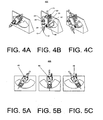
- FIGs. 4A-C illustrate a geometric measurement instrument, including a goniometer, that may be one structural embodiment of the arrangement of FIG. 3A ;
- FIG. 7 illustrates yet another embodiment of a system for determining at least one geometric characteristic of an object
- beneficially wavefront sensor 137 is a Shack-Hartman wavefront sensor.
- a moiré deflectometer, a Tscherning aberrometer, or other suitable sensor or interferometer could be employed.
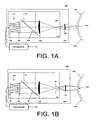
- positioner 163 adjusts these relative positions such that, at each relative position, light from light source 110 is delivered onto a subregion of the surface to be measured, and light scattered and/or reflected from the subregion of the surface to be measured is delivered to wavefront sensor 137. Positioner 163 adjusts the relative positions such that adjacent subregions scanned on the surface of object 105 have an overlap portion. Positioner 163 may include its own controller, or may be controlled by processor 170.
- positioner 163 is controlled to adjust a positional and/or rotational relationship between first surface 105a of object 105 and light source 110 and/or spatial filter 125 and/or wavefront sensor 137 to illuminate a desired subregion of first surface 105a.
- secondary positioner 160 may also be adjusted to modify the convergence (or divergence) of light directed from the lens 120 and towards the object 105, such that light reflected or refracted from a desired subregion of second surface 105b is delivered to wavefront sensor 137, while a majority (i.e., ⁇ 50%), or even perhaps a substantial majority (i.e., ⁇ 90%), of light from first surface 105a is now blocked by spatial aperture 125 from reaching wavefront sensor 137.
- the correct position can be found, for example, by monitoring the focal spot brightness on the detector 150 and searching for a second brightness peak, or by looking for some feature in the wavefront as reconstructed by wavefront sensor 137.
- This may be the position where the collimation of light into the wavefront sensor 137 has reached a predetermined value or even where the light is completely collimated. At this time, the reflection from front surface 105a is not in focus at spatial filter 125 and so spatial filter 125 blocks a majority or a substantial majority of this light.
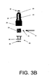
- FIGs. 3A-B illustrate two exemplary arrangements for a geometric measurement system which may be employed for geometric measurement system 100.
- the arrangements of FIGs. 3A-B each include: light emitting element 10 (e.g., an LED or diode laser in the visible, near-infrared, infrared, or ultraviolet wavelength bands of the electromagnetic spectrum) and collimator 15 as a light source; beamsplitter 20; microscope assembly 22 including image relay lens 25, pinhole (aperture) 30 (not visible in FIGs. 3A-B ), objective lens 35; and sensor 60, comprising an optical element 50 and a detector array (e.g., a charge-coupled device (CCD)) 55.
- Element 45 is an object under measurement.
- sensor 60 may be a Shack-Hartmann wavefront sensor, wherein optical element 50 is a lenslet array that generates light spots that are focused on detector array 55.
- detector array 55 detects the focal points of the light spots produced by lenslet array 50 to determine a wavefront of light received back from object 45.
- the output of detector 60 is provided to a processor (not shown in FIGs. 3A-B ), such as processor 170 in FIGs. 1A-B .
- Wavefronts from a plurality of subregions of object 45 are then stitched together to form a combined wavefront for a larger region (perhaps an entire surface area) of object 45, as described above.
- Light that is diffracted by this grating will be diffracted into a +1 diffraction order 770 and a -1 diffraction order 780 (and other orders depending on the exact structure of the grating).
- Some light will be undiffracted and hence stay in a zeroth diffraction order 775.
- the +1 order 770 has an effective negative focal power and the light spreads but also has net tilt
- the -1 order 780 has a positive focal power and so the light is concentrated, also with net tilt in the other direction.
- This arrangement may find particular benefit when one of the surfaces of object 704 has a particularly weak reflection.
- one of the surfaces may have an anti-reflective coating or may be in contact with another element (not shown) that has a similar refractive index to that of object 704.
- another element not shown
- the object is the cornea of an eye or part of a compound lens, such as an achromat lens.
- sensor 60 which in this case is a phase diversity sensor.
- Sensor 60 comprises a CCD camera with a lens and diffraction grating placed in front; so, conceptually, it looks very much like a wavefront sensor.
- the phase diversity sensor uses a diffraction grating with a specially curved grating field to create images before and after a focal plane. This allows different parts of a 3D object to be measured simultaneously.
- FIG. 8 shows a block diagram of yet another embodiment of a geometric measurement system 800 for determining at least one geometric characteristic of an object 805, and an associated method of determining at least one geometric characteristic of the object 805, using a white light interferometer.
- the optical path length traveled by the second portion of the light is adjusted again until detector 825 outputs a signal indicating a second interference fringe caused by light refracted or reflected by a second surface of object 805.
- an interference fringe is only produced when the optical path lengths traveled by the first and second portions of the light are the same, it is possible to determine a distance to (and thereby the position of) a location on the surface of object 805 from which the light is reflected or refracted by determining the optical path length traveled by the second portion of the light reflected by mirror 835 when the detector 835 outputs the signal indicating the occurrence of an interference fringe.
- this optical path length may be determined from a positional scale associated with positioner 855.
- geometric measurement system 800 can be used to produce profiles of a contact lens' geometry including base curvature, front curvature and thickness.
- profiles of a contact lens' geometry including base curvature, front curvature and thickness.
- multiple meridians can also be measured and analyzed.
Landscapes
- Physics & Mathematics (AREA)
- Health & Medical Sciences (AREA)
- Life Sciences & Earth Sciences (AREA)
- Spectroscopy & Molecular Physics (AREA)
- General Physics & Mathematics (AREA)
- Engineering & Computer Science (AREA)
- Veterinary Medicine (AREA)
- Heart & Thoracic Surgery (AREA)
- Medical Informatics (AREA)
- Molecular Biology (AREA)
- Surgery (AREA)
- Animal Behavior & Ethology (AREA)
- General Health & Medical Sciences (AREA)
- Public Health (AREA)
- Biomedical Technology (AREA)
- Ophthalmology & Optometry (AREA)
- Biophysics (AREA)
- Geometry (AREA)
- Chemical & Material Sciences (AREA)
- Analytical Chemistry (AREA)
- Length Measuring Devices By Optical Means (AREA)
- Testing Of Optical Devices Or Fibers (AREA)
Claims (15)
- Verfahren zum Bestimmen mindestens einer geometrischen Eigenschaft eines Gegenstands (105), der eine erste Oberfläche (105a) und eine zweite Oberfläche (105b) aufweist, wobei mindestens eine der ersten und der zweiten Oberfläche eine wesentliche Lichtmenge durchlässt, wobei das Verfahren gekennzeichnet ist durch:(a) Einstellen einer Positionsbeziehung zwischen der ersten Oberfläche des Gegenstands und einer Lichtquelle (110) zum Beleuchten nur eines Teilbereichs der ersten Oberfläche des Gegenstands, wobei ein Teil des Lichts, das den Teilbereich der ersten Oberfläche des Gegenstands beleuchtet, durch den Gegenstand zu der zweiten Oberfläche des Gegenstands hindurchtritt,(b) Leiten von Licht von dem Teilbereich der ersten Oberfläche des Gegenstands zu einem Wellenfrontsensor (137), während verhindert wird, dass ein Großteil des Lichts von der zweiten Oberfläche des Gegenstands den Wellenfrontsensor erreicht,(c) Bestimmen einer Wellenfront von Licht, das von dem Teilbereich der ersten Oberfläche mit einem Wellenfrontsensor empfangen worden ist,(d) Wiederholen der Schritte (a) bis (c) für eine Mehrzahl von verschiedenen Teilbereichen, die einen Messbereich für die erste Oberfläche des Gegenstands bilden, wobei benachbarte Teilbereiche einen überlappenden Abschnitt aufweisen,(e) Zusammensetzen der Wellenfronten, die bei jeder Ausführung des Schritts (c) bestimmt worden sind, einschließlich Ableitungen der Wellenfronten in den überlappenden Abschnitten, zum Aufbauen einer Wellenfront von Licht, das von dem Messbereich der ersten Oberfläche des Gegenstands empfangen worden ist, und(f) Bestimmen mindestens eines Formparameters der ersten Oberfläche des Gegenstands aus der aufgebauten Wellenfront.
- Verfahren nach Anspruch 1, bei dem das Einstellen einer Positionsbeziehung zwischen einer ersten Oberfläche (105a) des Gegenstands (105) und einer Lichtquelle (110) zum Beleuchten eines Teilbereichs der ersten Oberfläche des Gegen-stands mindestens eines von einem Drehen des Gegenstands bezogen auf die Lichtquelle und einem Drehen der Lichtquelle bezogen auf den Gegenstand umfasst.
- Verfahren nach Anspruch 1, bei dem das Einstellen einer Positionsbeziehung zwischen einer ersten Oberfläche (105a) des Gegenstands (105) und einer Lichtquelle (110) zum Beleuchten eines Teilbereichs der ersten Oberfläche des Gegen-stands mindestens eines von einem Neigen des Gegenstands bezogen auf die Lichtquelle und einem Neigen der Lichtquelle bezogen auf den Gegenstand umfasst.
- Verfahren nach Anspruch 1, bei dem das Bestimmen der Wellenfront von Licht, das von dem Teilbereich der ersten Oberfläche (105a) mit dem Wellenfrontsensor (137) empfangen worden ist, umfasst:Leiten des Lichts, das von dem Teilbereich der ersten Oberfläche empfangen worden ist, zu einem Lichtpunkterzeuger (50) undErfassen von Positionen von Brennpunkten von Lichtpunkten von dem Lichtpunkterzeuger.
- Verfahren nach Anspruch 1, bei dem das Leiten von Licht von dem Teilbereich der ersten Oberfläche (105a) des Gegenstands (105) zu dem Wellenfrontsensor (137), während verhindert wird, dass ein Großteil des Lichts von der zweiten Oberfläche (105b) des Gegenstands den Wellenfrontsensor erreicht, das Leiten des Lichts von dem Teilbereich der ersten Oberfläche des Gegenstands und von der zweiten Oberfläche des Gegenstands durch ein räumliches Filter (125) zum räumlichen Filtern des Lichts und das Leiten des räumlich gefilterten Lichts zu dem Wellenfrontsensor umfasst.
- Verfahren nach Anspruch 1, bei dem das Zusammensetzen das Bestimmen einer Wellenfront in den überlappenden Abschnitten durch eines von: (a) Verwenden eines Fehlerminimierungsalgorithmus und (b) Mitteln der Wellenfronten in den überlappenden Abschnitten der benachbarten Teilbereiche umfasst.
- Verfahren nach Anspruch 1, bei dem das Einstellen einer Positionsbeziehung zwischen der ersten Oberfläche (105a) des Gegenstands (105) und einer Lichtquelle (110) zum Beleuchten eines Teilbereichs der ersten Oberfläche des Gegenstands das Suchen eines Helligkeitspeaks an dem Wellenfrontdetektor umfasst.
- Verfahren nach Anspruch 1, ferner umfassend:(f) Einstellen einer Positionsbeziehung zwischen der zweiten Oberfläche (105b) des Gegenstands (105) und einer Lichtquelle (110) zum Beleuchten eines Teilbereichs der ersten Oberfläche (105a) des Gegenstands,(g) Leiten von Licht von dem Teilbereich der zweiten Oberfläche des Gegenstands zu dem Wellenfrontsensor (137), während verhindert wird, dass ein Großteil des Lichts von der ersten Oberfläche des Gegenstands den Wellenfrontsensor erreicht,(h) Bestimmen einer Wellenfront von Licht, das von dem Teilbereich der zweiten Oberfläche mit dem Wellenfrontsensor empfangen worden ist,(i) Wiederholen der Schritte (f) bis (h) für eine Mehrzahl von verschiedenen Teilbereichen, die einen Messbereich für die zweite Oberfläche des Gegenstands bilden, wobei benachbarte Teilbereiche einen überlappenden Abschnitt aufweisen,(j) Zusammensetzen der Wellenfronten, die bei jeder Ausführung des Schritts (i) bestimmt worden sind, einschließlich Ableitungen der Wellenfronten in den überlappenden Abschnitten, zum Aufbauen der Wellenfront von Licht, das von dem Messbereich der zweiten Oberfläche des Gegenstands empfangen worden ist, und (k) Bestimmen mindestens eines Formparameters der zweiten Oberfläche des Gegenstands aus der aufgebauten Wellenfront.
- System (100) zum Bestimmen mindestens einer geometrischen Eigenschaft eines Gegenstands (105), der eine erste Oberfläche, die eine wesentliche Lichtmenge durchlässt, und eine zweite Oberfläche (105b) aufweist, wobei das System umfasst:eine Lichtquelle (110),einen Wellenfrontsensor (137), wobei das System gekennzeichnet ist durch:ein optisches System (120, 130), das angepasst ist, Licht von der Lichtquelle nur zu einem Teilbereich der zu messenden ersten Oberfläche des Gegenstands zu leiten, und Licht von dem Teilbereich der zu messenden ersten Oberfläche des Gegenstands zu dem Wellenfrontsensor zu leiten, wobei ein Teil des Lichts, der zu dem Teilbereich der zu messenden ersten Oberfläche geleitet wird, durch den Gegen-stand zu der zweiten Oberfläche des Gegenstands, die nicht gemessen wird, hindurchtritt,eine Positioniereinrichtung (163), die angepasst ist, relative Positionen der Lichtquelle und der zu messenden ersten Oberfläche so einzustellen, dass bei jeder relativen Position das Licht von der Lichtquelle zu einem anderen Teilbereich der zu messenden ersten Oberfläche geleitet wird, und Licht von dem Teilbereich der zu messenden ersten Oberfläche zu dem Wellenfrontsensor geleitet wird, wobei die Positioniereinrichtung die relativen Positionen derart einstellt, dass benachbarte Teilbereiche einen überlappenden Abschnitt aufweisen,einen Prozessor (170), der angepasst ist, Wellenfronten zusammenzusetzen, die durch den Wellenfrontsensor für verschiedene Teilbereiche der zu messenden ersten Oberfläche an den relativen Positionen, die durch die Positioniereinrichtung bereitgestellt werden, gemessen worden sind, einschließlich Verwenden von Ableitungen von Wellenfronten in überlappenden Abschnitten, zum Aufbauen einer Wellenfront von Licht, das von einem Messbereich der zu messenden Oberfläche empfangen worden ist,wobei das optische System ein räumliches Filter (125) umfasst, das angepasst ist, zu verhindern, dass ein Großteil des Lichts von der zweiten Oberfläche des Gegenstands, die nicht gemessen wird, den Wellenfrontsensor erreicht, undwobei die Positioniereinrichtung auch angepasst ist, einen Abstand zwischen dem räumlichen Filter und der zu messenden ersten Oberfläche des Gegenstands einzustellen.
- System nach Anspruch 9, bei dem das räumliche Filter ein räumlicher Lichtmodulator (125) ist.
- System nach Anspruch 9, bei dem das räumliche Filter (125) so ausgebildet ist, dass die erste (1 05a) und die zweite (1 05b) Oberfläche zur Messung voneinander isoliert werden.
- System nach Anspruch 9, bei dem das optische System zwei Linsen (120, 130) umfasst, wobei das räumliche Filter (125) in einem Strahlengang zwischen den zwei Linsen angeordnet ist.
- System nach Anspruch 9, bei dem die Positioniereinrichtung (163) die relativen Positionen in drei Dimensionen einstellt.
- System nach Anspruch 9, bei dem die Positioniereinrichtung (163) eines von einem Mittel zum Drehen der Lichtquelle und einem Mittel zum Drehen des Gegenstands (105) umfasst.
- System nach Anspruch 9, bei dem die Positioniereinrichtung (163) eines von einem Mittel zum Neigen der Lichtquelle und einem Mittel zum Neigen des Gegenstands (105) umfasst.
Applications Claiming Priority (2)
| Application Number | Priority Date | Filing Date | Title |
|---|---|---|---|
| US78990106P | 2006-04-07 | 2006-04-07 | |
| PCT/US2007/008860 WO2007117694A2 (en) | 2006-04-07 | 2007-04-09 | Geometric measurement system and method of measuring a geometric characteristic of an object |
Publications (3)
| Publication Number | Publication Date |
|---|---|
| EP2008058A2 EP2008058A2 (de) | 2008-12-31 |
| EP2008058A4 EP2008058A4 (de) | 2011-02-16 |
| EP2008058B1 true EP2008058B1 (de) | 2012-12-05 |
Family
ID=38581691
Family Applications (1)
| Application Number | Title | Priority Date | Filing Date |
|---|---|---|---|
| EP07755212A Active EP2008058B1 (de) | 2006-04-07 | 2007-04-09 | Geometrisches messsystem und verfahren zur messung der geometrischen eigenschaft eines objekts |
Country Status (5)
| Country | Link |
|---|---|
| US (4) | US7583389B2 (de) |
| EP (1) | EP2008058B1 (de) |
| AU (1) | AU2007235239B2 (de) |
| CA (1) | CA2648305C (de) |
| WO (1) | WO2007117694A2 (de) |
Families Citing this family (73)
| Publication number | Priority date | Publication date | Assignee | Title |
|---|---|---|---|---|
| US7303582B2 (en) * | 2003-03-21 | 2007-12-04 | Advanced Medical Optics, Inc. | Foldable angle-fixated intraocular lens |
| ES2665536T3 (es) | 2004-04-20 | 2018-04-26 | Alcon Research, Ltd. | Microscopio quirúrgico y sensor de frente de onda integrados |
| DE102005040749B3 (de) * | 2005-08-26 | 2007-01-25 | Heraeus Quarzglas Gmbh & Co. Kg | Verfahren zur interferometrischen Messung einer optischen Eigenschaft eines Prüflings sowie zur Durchführung des Verfahrens geeignete Vorrichtung |
| US7993398B2 (en) * | 2007-04-24 | 2011-08-09 | Abbott Medical Optics Inc. | Angle indicator for capsular bag size measurement |
| US9216080B2 (en) | 2007-08-27 | 2015-12-22 | Amo Groningen B.V. | Toric lens with decreased sensitivity to cylinder power and rotation and method of using the same |
| US8974526B2 (en) | 2007-08-27 | 2015-03-10 | Amo Groningen B.V. | Multizonal lens with extended depth of focus |
| FR2920536B1 (fr) * | 2007-08-29 | 2010-03-12 | Thales Sa | Dispositif de mesure de la fonction de transfert de modulation d'instruments optiques de grande dimension |
| US8118429B2 (en) * | 2007-10-29 | 2012-02-21 | Amo Wavefront Sciences, Llc. | Systems and methods of phase diversity wavefront sensing |
| CA2912003C (en) * | 2007-10-30 | 2017-07-18 | Amo Wavefront Sciences, Llc | System and methods of phase diversity wavefront sensing |
| US7594729B2 (en) | 2007-10-31 | 2009-09-29 | Wf Systems, Llc | Wavefront sensor |
| US7723657B2 (en) * | 2007-11-16 | 2010-05-25 | Mitutoyo Corporation | Focus detection apparatus having extended detection range |
| EP2232198B1 (de) | 2008-01-08 | 2015-06-24 | AMO WaveFront Sciences, LLC | Systeme und verfahren zur messung einer oberflächenform |
| CA2715537C (en) | 2008-02-15 | 2016-09-06 | Amo Regional Holdings | System, ophthalmic lens, and method for extending depth of focus |
| US8439498B2 (en) | 2008-02-21 | 2013-05-14 | Abbott Medical Optics Inc. | Toric intraocular lens with modified power characteristics |
| AU2009228146B2 (en) | 2008-03-28 | 2015-06-04 | Johnson & Johnson Surgical Vision, Inc. | Systems for ocular measurements |
| US8862447B2 (en) | 2010-04-30 | 2014-10-14 | Amo Groningen B.V. | Apparatus, system and method for predictive modeling to design, evaluate and optimize ophthalmic lenses |
| US8550624B2 (en) | 2008-11-06 | 2013-10-08 | Wavetec Vision Systems, Inc. | Optical angular measurement system for ophthalmic applications and method for positioning of a toric intraocular lens with increased accuracy |
| CA2741734C (en) * | 2008-11-18 | 2017-07-18 | Stryker Corporation | Endoscopic led light source having a feedback control system |
| US20110026033A1 (en) * | 2008-12-19 | 2011-02-03 | Metroalaser, Inc. | Optical Inspection Using Spatial Light Modulation |
| DE102009010019B4 (de) * | 2009-02-21 | 2012-05-31 | Jos. Schneider Optische Werke Gmbh | Verfahren zum berührungslosen Messen der Topographie |
| US8876290B2 (en) | 2009-07-06 | 2014-11-04 | Wavetec Vision Systems, Inc. | Objective quality metric for ocular wavefront measurements |
| CN102497833B (zh) | 2009-07-14 | 2014-12-03 | 波技术视觉系统公司 | 眼科手术测量系统 |
| EP2818130B1 (de) | 2009-07-14 | 2017-09-27 | WaveTec Vision Systems, Inc. | Bestimmung der effektiven Linsenposition einer Intraokularlinse mit einer aphaken Brechkraft |
| MY172009A (en) | 2009-10-16 | 2019-11-11 | Alcon Inc | Process for manufacturing an ophthalmic lens |
| CA2784782C (en) | 2009-12-18 | 2018-02-27 | Hendrik A. Weeber | Limited echelette lens, systems and methods |
| US9817246B2 (en) | 2010-12-01 | 2017-11-14 | Amo Groningen B.V. | Multifocal lens having an optical add power progression, and a system and method of providing same |
| JP5721420B2 (ja) * | 2010-12-17 | 2015-05-20 | キヤノン株式会社 | 計測方法及び計測装置 |
| JP6007466B2 (ja) * | 2010-12-27 | 2016-10-12 | 株式会社ニデック | 角膜形状測定装置 |
| JP5854680B2 (ja) * | 2011-07-25 | 2016-02-09 | キヤノン株式会社 | 撮像装置 |
| US9214368B2 (en) * | 2011-07-27 | 2015-12-15 | Ipg Photonics Corporation | Laser diode array with fiber optic termination for surface treatment of materials |
| JP5808194B2 (ja) * | 2011-08-15 | 2015-11-10 | キヤノン株式会社 | 形状計測方法、形状計測装置、プログラム及び記録媒体 |
| US9182289B2 (en) * | 2011-10-14 | 2015-11-10 | Canon Kabushiki Kaisha | Apparatus and method for estimating wavefront parameters |
| US20140362371A1 (en) * | 2011-12-20 | 2014-12-11 | 3M Innovative Properties Company | Sensor for measuring surface non-uniformity |
| EP2637011A1 (de) * | 2012-03-09 | 2013-09-11 | Essilor International | Verfahren und Vorrichtung zur Messung der geometrischen Struktur einer optischen Komponente |
| DE102012204704A1 (de) | 2012-03-23 | 2013-09-26 | Carl Zeiss Smt Gmbh | Messvorrichtung zum Vermessen einer Abbildungsgüte eines EUV-Objektives |
| JP5988643B2 (ja) * | 2012-03-26 | 2016-09-07 | キヤノン株式会社 | 計測装置、計測方法及び光学部品の製造方法 |
| GB201205491D0 (en) * | 2012-03-28 | 2012-05-09 | Ucl Business Plc | Measuring surface curvature |
| EP2656781A1 (de) * | 2012-04-24 | 2013-10-30 | Popovic, Zoran | Leitsternerzeugung |
| US9072462B2 (en) | 2012-09-27 | 2015-07-07 | Wavetec Vision Systems, Inc. | Geometric optical power measurement device |
| JP6029429B2 (ja) * | 2012-11-19 | 2016-11-24 | キヤノン株式会社 | 波面収差測定方法、波面収差測定装置、及び光学系の製造方法 |
| CA2877203A1 (en) | 2012-12-04 | 2014-06-12 | Amo Groningen B.V. | Lenses, systems and methods for providing binocular customized treatments to correct presbyopia |
| US9019485B2 (en) | 2013-03-11 | 2015-04-28 | Lumetrics, Inc. | Apparatus and method for evaluation of optical elements |
| US9335247B2 (en) | 2013-03-14 | 2016-05-10 | Cytonome/St, Llc | Assemblies and methods for reducing optical crosstalk in particle processing systems |
| EP2967299B1 (de) | 2013-03-15 | 2022-11-30 | Stryker Corporation | Endoskopische lichtquelle und bildgebungssystem |
| CN103267489A (zh) * | 2013-05-20 | 2013-08-28 | 中国计量科学研究院 | 哈特曼波前传感器的校准系统及校准方法 |
| CN103431837B (zh) * | 2013-08-23 | 2015-04-29 | 饶丰 | 基于哈特曼传感器的人眼轴向色差和横向色差测量装置及其方法 |
| JP2015087198A (ja) * | 2013-10-30 | 2015-05-07 | キヤノン株式会社 | 計測装置及び計測方法 |
| JP6452086B2 (ja) * | 2013-10-31 | 2019-01-16 | キヤノン株式会社 | 形状算出装置及び方法、計測装置、物品製造方法、及び、プログラム |
| US9506837B2 (en) | 2014-04-16 | 2016-11-29 | Lumetrics, Inc. | Toric intraocular lens measurement apparatus and method |
| WO2016123167A1 (en) * | 2015-01-28 | 2016-08-04 | The United States Of America, As Represented By The Secretary, Department Of Health & Human Services | Confocal laser method and device for measurement of optical properties of toric intraocular lenses |
| KR101825923B1 (ko) * | 2015-09-03 | 2018-03-22 | 주식회사 이오테크닉스 | 레이저 가공장치 및 레이저 가공방법 |
| CA3013857A1 (en) | 2016-02-09 | 2017-08-17 | Amo Groningen B.V. | Progressive power intraocular lens, and methods of use and manufacture |
| AU2017237090B2 (en) | 2016-03-23 | 2021-10-21 | Johnson & Johnson Surgical Vision, Inc. | Ophthalmic apparatus with corrective meridians having extended tolerance band by modifying refractive powers in uniform meridian distribution |
| WO2017165623A1 (en) | 2016-03-23 | 2017-09-28 | Abbott Medical Optics Inc. | Power calculator for an ophthalmic apparatus with corrective meridians having extended tolerance or operation band |
| US10690904B2 (en) | 2016-04-12 | 2020-06-23 | Stryker Corporation | Multiple imaging modality light source |
| KR101750883B1 (ko) | 2016-06-14 | 2017-06-27 | 주식회사 이오비스 | 비전 검사 시스템의 3차원 형상 측정 방법 |
| CN107957251B (zh) * | 2016-10-18 | 2019-12-20 | 中国计量大学 | 基于计算机辅助校正的反射球面通用化检测方法 |
| US11013594B2 (en) | 2016-10-25 | 2021-05-25 | Amo Groningen B.V. | Realistic eye models to design and evaluate intraocular lenses for a large field of view |
| US10739227B2 (en) | 2017-03-23 | 2020-08-11 | Johnson & Johnson Surgical Vision, Inc. | Methods and systems for measuring image quality |
| CN107167299B (zh) * | 2017-06-13 | 2019-07-05 | 中国科学院光电技术研究所 | 一种基于联合探测和相位拟合的波前检测仪 |
| CA3082053A1 (en) | 2017-11-30 | 2019-06-06 | Amo Groningen B.V. | Intraocular lenses that improve post-surgical spectacle independent and methods of manufacturing thereof |
| JP2019105561A (ja) * | 2017-12-13 | 2019-06-27 | 大塚電子株式会社 | 測定装置および、それに用いられるサンプルホルダ |
| US10876924B2 (en) * | 2018-02-08 | 2020-12-29 | Amo Groningen B.V. | Wavefront based characterization of lens surfaces based on reflections |
| EP3749170B1 (de) | 2018-02-08 | 2026-04-29 | AMO Groningen B.V. | Psychophysisches verfahren zur charakterisierung von visuellen symptomen |
| US10895517B2 (en) * | 2018-02-08 | 2021-01-19 | Amo Groningen B.V. | Multi-wavelength wavefront system and method for measuring diffractive lenses |
| CN109307480B (zh) * | 2018-09-30 | 2020-08-14 | 中国计量大学 | 一种透射元件多表面面形检测方法 |
| EP3908820A4 (de) * | 2019-01-10 | 2022-10-05 | 6 Over 6 Vision Ltd | Vorrichtung, system und verfahren zur bestimmung einer oder mehrerer parameter einer linse |
| CN110726381B (zh) * | 2019-11-22 | 2021-10-15 | 中国科学院长春光学精密机械与物理研究所 | 一种光学自由曲面全频段像差检测系统及检测方法 |
| US11886046B2 (en) | 2019-12-30 | 2024-01-30 | Amo Groningen B.V. | Multi-region refractive lenses for vision treatment |
| US12239529B2 (en) | 2021-03-09 | 2025-03-04 | Amo Groningen B.V. | Refractive extended depth of focus intraocular lens, and methods of use and manufacture |
| EP4333685B1 (de) | 2021-05-05 | 2026-01-14 | AMO Groningen B.V. | Ringhalometersystem und verfahren zur quantifizierung von dysphotopsien |
| WO2023099745A1 (en) | 2021-12-03 | 2023-06-08 | Amo Groningen B.V. | Lenses having multi-ring design for vision treatment |
| CN119845145B (zh) * | 2025-01-02 | 2025-09-23 | 中山市光大光学仪器有限公司 | 一种棱镜透镜组合光学套件及其生产方法 |
Family Cites Families (34)
| Publication number | Priority date | Publication date | Assignee | Title |
|---|---|---|---|---|
| JPS5838839A (ja) * | 1981-08-31 | 1983-03-07 | Tokyo Optical Co Ltd | 屈折率測定装置 |
| US4707137A (en) | 1985-10-25 | 1987-11-17 | Laser Magnetic Storage International Company | Device and method for testing the wave front quality of optical components |
| US5333049A (en) | 1991-12-06 | 1994-07-26 | Hughes Aircraft Company | Apparatus and method for interferometrically measuring the thickness of thin films using full aperture irradiation |
| US5416586A (en) | 1993-10-15 | 1995-05-16 | Tropel Corporation | Method of testing aspherical optical surfaces with an interferometer |
| JP3548259B2 (ja) | 1994-04-07 | 2004-07-28 | ペンタックス株式会社 | 光磁気ヘッド装置 |
| US5563709A (en) * | 1994-09-13 | 1996-10-08 | Integrated Process Equipment Corp. | Apparatus for measuring, thinning and flattening silicon structures |
| KR100200837B1 (ko) | 1995-01-24 | 1999-06-15 | 윤종용 | 다층 기록막을 갖는 광디스크를 위한 광픽업 |
| ATA107495A (de) * | 1995-06-23 | 1996-06-15 | Fercher Adolf Friedrich Dr | Kohärenz-biometrie und -tomographie mit dynamischem kohärentem fokus |
| US5641437A (en) * | 1995-09-29 | 1997-06-24 | Johnson & Johnson Vision Products, Inc. | Marking of mold inserts to produce marked contact lenses |
| US5629765A (en) * | 1995-12-15 | 1997-05-13 | Adaptive Optics Associates, Inc. | Wavefront measuring system with integral geometric reference (IGR) |
| US5867250A (en) * | 1996-05-03 | 1999-02-02 | Baron; William S. | Apparatus and method for optically mapping front and back surface topographies of an object |
| JP3309743B2 (ja) * | 1996-11-27 | 2002-07-29 | 富士ゼロックス株式会社 | 形状測定方法及び装置 |
| US6201601B1 (en) | 1997-09-19 | 2001-03-13 | Kla-Tencor Corporation | Sample inspection system |
| US6424407B1 (en) | 1998-03-09 | 2002-07-23 | Otm Technologies Ltd. | Optical translation measurement |
| US6414752B1 (en) * | 1999-06-18 | 2002-07-02 | Kla-Tencor Technologies Corporation | Method and apparatus for scanning, stitching, and damping measurements of a double-sided metrology inspection tool |
| US6184974B1 (en) * | 1999-07-01 | 2001-02-06 | Wavefront Sciences, Inc. | Apparatus and method for evaluating a target larger than a measuring aperture of a sensor |
| GB2353392A (en) | 1999-08-18 | 2001-02-21 | Secr Defence | Imaging system suitable for use in multi-layer optical data storage applications |
| US6624896B1 (en) | 1999-10-18 | 2003-09-23 | Wavefront Sciences, Inc. | System and method for metrology of surface flatness and surface nanotopology of materials |
| US6550917B1 (en) * | 2000-02-11 | 2003-04-22 | Wavefront Sciences, Inc. | Dynamic range extension techniques for a wavefront sensor including use in ophthalmic measurement |
| US7455407B2 (en) * | 2000-02-11 | 2008-11-25 | Amo Wavefront Sciences, Llc | System and method of measuring and mapping three dimensional structures |
| FR2813391B1 (fr) | 2000-08-22 | 2002-11-29 | Essilor Int | Procede et appareil de mesure en transmission de la structure geometrique d'un composant optique |
| US7317531B2 (en) * | 2002-12-05 | 2008-01-08 | Kla-Tencor Technologies Corporation | Apparatus and methods for detecting overlay errors using scatterometry |
| WO2003041609A2 (en) * | 2001-11-09 | 2003-05-22 | Wavefront Sciences, Inc. | System and method for perfoming optical corrective procedure with real-time feedback |
| UA59488C2 (uk) * | 2001-10-03 | 2003-09-15 | Василь Васильович Молебний | Спосіб вимірювання хвильових аберацій ока та пристрій для його здійснення (варіанти) |
| DE60228940D1 (de) * | 2001-03-15 | 2008-10-30 | Amo Wavefront Sciences Llc | Hren zur abbildung eines optischen systems |
| IL143503A0 (en) * | 2001-05-31 | 2002-04-21 | Visionix Ltd | Aberration correction spectacle lens |
| US6624894B2 (en) | 2001-06-25 | 2003-09-23 | Veeco Instruments Inc. | Scanning interferometry with reference signal |
| US6956657B2 (en) * | 2001-12-18 | 2005-10-18 | Qed Technologies, Inc. | Method for self-calibrated sub-aperture stitching for surface figure measurement |
| US6972850B2 (en) * | 2002-03-06 | 2005-12-06 | Canon Kabushiki Kaisha | Method and apparatus for measuring the shape of an optical surface using an interferometer |
| DE10302849A1 (de) * | 2003-01-23 | 2004-07-29 | Carl Zeiss Meditec Ag | Verfahren und Anordnung zur Messung der Dispersion in transparenten Medien |
| GB0314444D0 (en) * | 2003-06-20 | 2003-07-23 | Univ Heriot Watt | Novel wavefront sensor |
| GB2404014B (en) | 2003-07-18 | 2006-06-28 | Taylor Hobson Ltd | Surface profiling method and apparatus |
| DE10360570B4 (de) * | 2003-12-22 | 2006-01-12 | Carl Zeiss | Optisches Meßsystem und optisches Meßverfahren |
| WO2007005527A2 (en) | 2005-06-30 | 2007-01-11 | Wavefront Sciences, Inc. | Method and system for measuring the curvature of an optical surface |
-
2007
- 2007-04-09 US US11/783,314 patent/US7583389B2/en active Active
- 2007-04-09 US US11/783,316 patent/US7616330B2/en active Active
- 2007-04-09 CA CA2648305A patent/CA2648305C/en not_active Expired - Fee Related
- 2007-04-09 US US11/783,315 patent/US7623251B2/en active Active
- 2007-04-09 EP EP07755212A patent/EP2008058B1/de active Active
- 2007-04-09 AU AU2007235239A patent/AU2007235239B2/en not_active Ceased
- 2007-04-09 WO PCT/US2007/008860 patent/WO2007117694A2/en not_active Ceased
-
2009
- 2009-11-06 US US12/613,848 patent/US7969585B2/en active Active
Also Published As
| Publication number | Publication date |
|---|---|
| CA2648305A1 (en) | 2007-10-18 |
| US7623251B2 (en) | 2009-11-24 |
| WO2007117694A3 (en) | 2008-04-17 |
| US20100277694A1 (en) | 2010-11-04 |
| AU2007235239B2 (en) | 2013-01-17 |
| EP2008058A4 (de) | 2011-02-16 |
| US20070236703A1 (en) | 2007-10-11 |
| US7969585B2 (en) | 2011-06-28 |
| CA2648305C (en) | 2012-10-16 |
| US20070236702A1 (en) | 2007-10-11 |
| EP2008058A2 (de) | 2008-12-31 |
| WO2007117694A2 (en) | 2007-10-18 |
| US20070236701A1 (en) | 2007-10-11 |
| US7583389B2 (en) | 2009-09-01 |
| AU2007235239A1 (en) | 2007-10-18 |
| US7616330B2 (en) | 2009-11-10 |
Similar Documents
| Publication | Publication Date | Title |
|---|---|---|
| US7969585B2 (en) | Geometric measurement system and method of measuring a geometric characteristic of an object | |
| US7455407B2 (en) | System and method of measuring and mapping three dimensional structures | |
| JP5783899B2 (ja) | 近ゼロサブ開口測定のスティッチング | |
| US6819413B2 (en) | Method and system for sensing and analyzing a wavefront of an optically transmissive system | |
| US8913236B2 (en) | Method and device for measuring freeform surfaces | |
| JP2004530898A (ja) | 非球面表面および波面に対する干渉計スキャニング | |
| US12292274B2 (en) | Interferometric lens aligner and method | |
| US10823636B2 (en) | Method and apparatus for the determination of the index of refraction of lens material | |
| AU2019219296B2 (en) | Multi-wavelength wavefront system and method for measuring diffractive lenses | |
| AU2019219238B2 (en) | Wavefront based characterization of lens surfaces based on reflections | |
| JP2005201703A (ja) | 干渉測定方法及び干渉測定システム | |
| Daly et al. | Mach Zehnder interferometer for measuring microlenses | |
| Simon et al. | Test of aspherics in the NIR with a diffractive optical element as null lens |
Legal Events
| Date | Code | Title | Description |
|---|---|---|---|
| PUAI | Public reference made under article 153(3) epc to a published international application that has entered the european phase |
Free format text: ORIGINAL CODE: 0009012 |
|
| 17P | Request for examination filed |
Effective date: 20081106 |
|
| AK | Designated contracting states |
Kind code of ref document: A2 Designated state(s): AT BE BG CH CY CZ DE DK EE ES FI FR GB GR HU IE IS IT LI LT LU LV MC MT NL PL PT RO SE SI SK TR |
|
| AX | Request for extension of the european patent |
Extension state: AL BA HR MK RS |
|
| RAP1 | Party data changed (applicant data changed or rights of an application transferred) |
Owner name: ABBOTT MEDICAL OPTICS INC. |
|
| RAP1 | Party data changed (applicant data changed or rights of an application transferred) |
Owner name: ABBOTT MEDICAL OPTICS INC. |
|
| A4 | Supplementary search report drawn up and despatched |
Effective date: 20110117 |
|
| 17Q | First examination report despatched |
Effective date: 20111110 |
|
| DAX | Request for extension of the european patent (deleted) | ||
| GRAP | Despatch of communication of intention to grant a patent |
Free format text: ORIGINAL CODE: EPIDOSNIGR1 |
|
| GRAS | Grant fee paid |
Free format text: ORIGINAL CODE: EPIDOSNIGR3 |
|
| GRAA | (expected) grant |
Free format text: ORIGINAL CODE: 0009210 |
|
| AK | Designated contracting states |
Kind code of ref document: B1 Designated state(s): AT BE BG CH CY CZ DE DK EE ES FI FR GB GR HU IE IS IT LI LT LU LV MC MT NL PL PT RO SE SI SK TR |
|
| REG | Reference to a national code |
Ref country code: GB Ref legal event code: FG4D |
|
| REG | Reference to a national code |
Ref country code: CH Ref legal event code: EP |
|
| REG | Reference to a national code |
Ref country code: AT Ref legal event code: REF Ref document number: 587504 Country of ref document: AT Kind code of ref document: T Effective date: 20121215 |
|
| REG | Reference to a national code |
Ref country code: IE Ref legal event code: FG4D |
|
| REG | Reference to a national code |
Ref country code: CH Ref legal event code: NV Representative=s name: CRONIN INTELLECTUAL PROPERTY, CH Ref country code: DE Ref legal event code: R096 Ref document number: 602007027157 Country of ref document: DE Effective date: 20130131 |
|
| REG | Reference to a national code |
Ref country code: CH Ref legal event code: NV Representative=s name: CRONIN INTELLECTUAL PROPERTY, CH |
|
| REG | Reference to a national code |
Ref country code: NL Ref legal event code: T3 |
|
| REG | Reference to a national code |
Ref country code: AT Ref legal event code: MK05 Ref document number: 587504 Country of ref document: AT Kind code of ref document: T Effective date: 20121205 |
|
| PG25 | Lapsed in a contracting state [announced via postgrant information from national office to epo] |
Ref country code: ES Free format text: LAPSE BECAUSE OF FAILURE TO SUBMIT A TRANSLATION OF THE DESCRIPTION OR TO PAY THE FEE WITHIN THE PRESCRIBED TIME-LIMIT Effective date: 20130316 Ref country code: FI Free format text: LAPSE BECAUSE OF FAILURE TO SUBMIT A TRANSLATION OF THE DESCRIPTION OR TO PAY THE FEE WITHIN THE PRESCRIBED TIME-LIMIT Effective date: 20121205 Ref country code: SE Free format text: LAPSE BECAUSE OF FAILURE TO SUBMIT A TRANSLATION OF THE DESCRIPTION OR TO PAY THE FEE WITHIN THE PRESCRIBED TIME-LIMIT Effective date: 20121205 Ref country code: LT Free format text: LAPSE BECAUSE OF FAILURE TO SUBMIT A TRANSLATION OF THE DESCRIPTION OR TO PAY THE FEE WITHIN THE PRESCRIBED TIME-LIMIT Effective date: 20121205 |
|
| REG | Reference to a national code |
Ref country code: LT Ref legal event code: MG4D |
|
| PG25 | Lapsed in a contracting state [announced via postgrant information from national office to epo] |
Ref country code: SI Free format text: LAPSE BECAUSE OF FAILURE TO SUBMIT A TRANSLATION OF THE DESCRIPTION OR TO PAY THE FEE WITHIN THE PRESCRIBED TIME-LIMIT Effective date: 20121205 Ref country code: PL Free format text: LAPSE BECAUSE OF FAILURE TO SUBMIT A TRANSLATION OF THE DESCRIPTION OR TO PAY THE FEE WITHIN THE PRESCRIBED TIME-LIMIT Effective date: 20121205 Ref country code: GR Free format text: LAPSE BECAUSE OF FAILURE TO SUBMIT A TRANSLATION OF THE DESCRIPTION OR TO PAY THE FEE WITHIN THE PRESCRIBED TIME-LIMIT Effective date: 20130306 Ref country code: LV Free format text: LAPSE BECAUSE OF FAILURE TO SUBMIT A TRANSLATION OF THE DESCRIPTION OR TO PAY THE FEE WITHIN THE PRESCRIBED TIME-LIMIT Effective date: 20121205 Ref country code: CY Free format text: LAPSE BECAUSE OF FAILURE TO SUBMIT A TRANSLATION OF THE DESCRIPTION OR TO PAY THE FEE WITHIN THE PRESCRIBED TIME-LIMIT Effective date: 20121205 |
|
| PG25 | Lapsed in a contracting state [announced via postgrant information from national office to epo] |
Ref country code: AT Free format text: LAPSE BECAUSE OF FAILURE TO SUBMIT A TRANSLATION OF THE DESCRIPTION OR TO PAY THE FEE WITHIN THE PRESCRIBED TIME-LIMIT Effective date: 20121205 |
|
| PG25 | Lapsed in a contracting state [announced via postgrant information from national office to epo] |
Ref country code: BE Free format text: LAPSE BECAUSE OF FAILURE TO SUBMIT A TRANSLATION OF THE DESCRIPTION OR TO PAY THE FEE WITHIN THE PRESCRIBED TIME-LIMIT Effective date: 20121205 Ref country code: EE Free format text: LAPSE BECAUSE OF FAILURE TO SUBMIT A TRANSLATION OF THE DESCRIPTION OR TO PAY THE FEE WITHIN THE PRESCRIBED TIME-LIMIT Effective date: 20121205 Ref country code: SK Free format text: LAPSE BECAUSE OF FAILURE TO SUBMIT A TRANSLATION OF THE DESCRIPTION OR TO PAY THE FEE WITHIN THE PRESCRIBED TIME-LIMIT Effective date: 20121205 Ref country code: BG Free format text: LAPSE BECAUSE OF FAILURE TO SUBMIT A TRANSLATION OF THE DESCRIPTION OR TO PAY THE FEE WITHIN THE PRESCRIBED TIME-LIMIT Effective date: 20130305 Ref country code: CZ Free format text: LAPSE BECAUSE OF FAILURE TO SUBMIT A TRANSLATION OF THE DESCRIPTION OR TO PAY THE FEE WITHIN THE PRESCRIBED TIME-LIMIT Effective date: 20121205 Ref country code: IS Free format text: LAPSE BECAUSE OF FAILURE TO SUBMIT A TRANSLATION OF THE DESCRIPTION OR TO PAY THE FEE WITHIN THE PRESCRIBED TIME-LIMIT Effective date: 20130405 |
|
| PG25 | Lapsed in a contracting state [announced via postgrant information from national office to epo] |
Ref country code: RO Free format text: LAPSE BECAUSE OF FAILURE TO SUBMIT A TRANSLATION OF THE DESCRIPTION OR TO PAY THE FEE WITHIN THE PRESCRIBED TIME-LIMIT Effective date: 20121205 Ref country code: PT Free format text: LAPSE BECAUSE OF FAILURE TO SUBMIT A TRANSLATION OF THE DESCRIPTION OR TO PAY THE FEE WITHIN THE PRESCRIBED TIME-LIMIT Effective date: 20130405 |
|
| PLBE | No opposition filed within time limit |
Free format text: ORIGINAL CODE: 0009261 |
|
| STAA | Information on the status of an ep patent application or granted ep patent |
Free format text: STATUS: NO OPPOSITION FILED WITHIN TIME LIMIT |
|
| PG25 | Lapsed in a contracting state [announced via postgrant information from national office to epo] |
Ref country code: DK Free format text: LAPSE BECAUSE OF FAILURE TO SUBMIT A TRANSLATION OF THE DESCRIPTION OR TO PAY THE FEE WITHIN THE PRESCRIBED TIME-LIMIT Effective date: 20121205 |
|
| 26N | No opposition filed |
Effective date: 20130906 |
|
| PG25 | Lapsed in a contracting state [announced via postgrant information from national office to epo] |
Ref country code: MC Free format text: LAPSE BECAUSE OF FAILURE TO SUBMIT A TRANSLATION OF THE DESCRIPTION OR TO PAY THE FEE WITHIN THE PRESCRIBED TIME-LIMIT Effective date: 20121205 |
|
| PG25 | Lapsed in a contracting state [announced via postgrant information from national office to epo] |
Ref country code: IT Free format text: LAPSE BECAUSE OF FAILURE TO SUBMIT A TRANSLATION OF THE DESCRIPTION OR TO PAY THE FEE WITHIN THE PRESCRIBED TIME-LIMIT Effective date: 20121205 |
|
| REG | Reference to a national code |
Ref country code: DE Ref legal event code: R097 Ref document number: 602007027157 Country of ref document: DE Effective date: 20130906 |
|
| REG | Reference to a national code |
Ref country code: IE Ref legal event code: MM4A |
|
| PG25 | Lapsed in a contracting state [announced via postgrant information from national office to epo] |
Ref country code: IE Free format text: LAPSE BECAUSE OF NON-PAYMENT OF DUE FEES Effective date: 20130409 |
|
| REG | Reference to a national code |
Ref country code: DE Ref legal event code: R082 Ref document number: 602007027157 Country of ref document: DE Representative=s name: ZEITLER VOLPERT KANDLBINDER PATENTANWAELTE PAR, DE |
|
| PG25 | Lapsed in a contracting state [announced via postgrant information from national office to epo] |
Ref country code: MT Free format text: LAPSE BECAUSE OF FAILURE TO SUBMIT A TRANSLATION OF THE DESCRIPTION OR TO PAY THE FEE WITHIN THE PRESCRIBED TIME-LIMIT Effective date: 20121205 |
|
| REG | Reference to a national code |
Ref country code: CH Ref legal event code: PUE Owner name: AMO WAVEFRONT SCIENCES, LLC, US Free format text: FORMER OWNER: ABBOTT MEDICAL OPTICS INC., US Ref country code: CH Ref legal event code: NV Representative=s name: NOVAGRAAF INTERNATIONAL SA, CH |
|
| REG | Reference to a national code |
Ref country code: GB Ref legal event code: 732E Free format text: REGISTERED BETWEEN 20150226 AND 20150304 |
|
| REG | Reference to a national code |
Ref country code: DE Ref legal event code: R082 Ref document number: 602007027157 Country of ref document: DE Representative=s name: ZEITLER VOLPERT KANDLBINDER PATENTANWAELTE PAR, DE Effective date: 20150224 Ref country code: DE Ref legal event code: R081 Ref document number: 602007027157 Country of ref document: DE Owner name: AMO WAVEFRONT SCIENCES, LLC, ALBUQUERQUE, US Free format text: FORMER OWNER: ABBOTT MEDICAL OPTICS INC., SANTA ANA, CALIF., US Effective date: 20150224 Ref country code: DE Ref legal event code: R082 Ref document number: 602007027157 Country of ref document: DE Representative=s name: ZEITLER VOLPERT KANDLBINDER PATENT- UND RECHTS, DE Effective date: 20150224 |
|
| REG | Reference to a national code |
Ref country code: NL Ref legal event code: SD Effective date: 20150511 |
|
| REG | Reference to a national code |
Ref country code: FR Ref legal event code: TP Owner name: AMO WAVEFRONT SCIENCES, LLC, US Effective date: 20150423 |
|
| PG25 | Lapsed in a contracting state [announced via postgrant information from national office to epo] |
Ref country code: TR Free format text: LAPSE BECAUSE OF FAILURE TO SUBMIT A TRANSLATION OF THE DESCRIPTION OR TO PAY THE FEE WITHIN THE PRESCRIBED TIME-LIMIT Effective date: 20121205 |
|
| PG25 | Lapsed in a contracting state [announced via postgrant information from national office to epo] |
Ref country code: LU Free format text: LAPSE BECAUSE OF NON-PAYMENT OF DUE FEES Effective date: 20130409 Ref country code: HU Free format text: LAPSE BECAUSE OF FAILURE TO SUBMIT A TRANSLATION OF THE DESCRIPTION OR TO PAY THE FEE WITHIN THE PRESCRIBED TIME-LIMIT; INVALID AB INITIO Effective date: 20070409 |
|
| REG | Reference to a national code |
Ref country code: FR Ref legal event code: PLFP Year of fee payment: 10 |
|
| REG | Reference to a national code |
Ref country code: FR Ref legal event code: PLFP Year of fee payment: 11 |
|
| REG | Reference to a national code |
Ref country code: FR Ref legal event code: PLFP Year of fee payment: 12 |
|
| PGFP | Annual fee paid to national office [announced via postgrant information from national office to epo] |
Ref country code: FR Payment date: 20190313 Year of fee payment: 13 |
|
| PGFP | Annual fee paid to national office [announced via postgrant information from national office to epo] |
Ref country code: NL Payment date: 20190412 Year of fee payment: 13 |
|
| PGFP | Annual fee paid to national office [announced via postgrant information from national office to epo] |
Ref country code: CH Payment date: 20190416 Year of fee payment: 13 |
|
| PGFP | Annual fee paid to national office [announced via postgrant information from national office to epo] |
Ref country code: GB Payment date: 20190403 Year of fee payment: 13 |
|
| REG | Reference to a national code |
Ref country code: CH Ref legal event code: PL |
|
| REG | Reference to a national code |
Ref country code: NL Ref legal event code: MM Effective date: 20200501 |
|
| PG25 | Lapsed in a contracting state [announced via postgrant information from national office to epo] |
Ref country code: CH Free format text: LAPSE BECAUSE OF NON-PAYMENT OF DUE FEES Effective date: 20200430 Ref country code: LI Free format text: LAPSE BECAUSE OF NON-PAYMENT OF DUE FEES Effective date: 20200430 Ref country code: FR Free format text: LAPSE BECAUSE OF NON-PAYMENT OF DUE FEES Effective date: 20200430 |
|
| GBPC | Gb: european patent ceased through non-payment of renewal fee |
Effective date: 20200409 |
|
| PG25 | Lapsed in a contracting state [announced via postgrant information from national office to epo] |
Ref country code: NL Free format text: LAPSE BECAUSE OF NON-PAYMENT OF DUE FEES Effective date: 20200501 |
|
| PG25 | Lapsed in a contracting state [announced via postgrant information from national office to epo] |
Ref country code: GB Free format text: LAPSE BECAUSE OF NON-PAYMENT OF DUE FEES Effective date: 20200409 |
|
| REG | Reference to a national code |
Ref country code: DE Ref legal event code: R082 Ref document number: 602007027157 Country of ref document: DE Representative=s name: KANDLBINDER, MARKUS, DIPL.-PHYS., DE |
|
| PGFP | Annual fee paid to national office [announced via postgrant information from national office to epo] |
Ref country code: DE Payment date: 20250305 Year of fee payment: 19 |