EP2008143B1 - System und verfahren für die bildgebung mit erweiterter fokustiefe und nicht kohärentem licht - Google Patents
System und verfahren für die bildgebung mit erweiterter fokustiefe und nicht kohärentem licht Download PDFInfo
- Publication number
- EP2008143B1 EP2008143B1 EP07736240A EP07736240A EP2008143B1 EP 2008143 B1 EP2008143 B1 EP 2008143B1 EP 07736240 A EP07736240 A EP 07736240A EP 07736240 A EP07736240 A EP 07736240A EP 2008143 B1 EP2008143 B1 EP 2008143B1
- Authority
- EP
- European Patent Office
- Prior art keywords
- optical
- unit
- replicas
- symmetrizing
- aperture
- Prior art date
- Legal status (The legal status is an assumption and is not a legal conclusion. Google has not performed a legal analysis and makes no representation as to the accuracy of the status listed.)
- Not-in-force
Links
- 238000003384 imaging method Methods 0.000 title claims abstract description 34
- 238000000034 method Methods 0.000 title claims description 15
- 230000003287 optical effect Effects 0.000 claims abstract description 61
- 238000009826 distribution Methods 0.000 claims abstract description 18
- 230000010076 replication Effects 0.000 claims abstract description 16
- 230000005540 biological transmission Effects 0.000 claims description 11
- 238000012545 processing Methods 0.000 claims description 6
- 238000006073 displacement reaction Methods 0.000 claims description 4
- 239000013307 optical fiber Substances 0.000 claims description 3
- 230000000903 blocking effect Effects 0.000 claims description 2
- 230000000694 effects Effects 0.000 description 5
- 238000012546 transfer Methods 0.000 description 5
- 230000001419 dependent effect Effects 0.000 description 4
- 238000013459 approach Methods 0.000 description 3
- 230000003362 replicative effect Effects 0.000 description 3
- 230000018199 S phase Effects 0.000 description 2
- 230000006978 adaptation Effects 0.000 description 2
- 238000005311 autocorrelation function Methods 0.000 description 2
- 230000005684 electric field Effects 0.000 description 2
- 230000004323 axial length Effects 0.000 description 1
- 230000001427 coherent effect Effects 0.000 description 1
- 230000002596 correlated effect Effects 0.000 description 1
- 230000000875 corresponding effect Effects 0.000 description 1
- 238000009795 derivation Methods 0.000 description 1
- 238000001514 detection method Methods 0.000 description 1
- 238000004134 energy conservation Methods 0.000 description 1
- 238000005516 engineering process Methods 0.000 description 1
- 230000001788 irregular Effects 0.000 description 1
- 239000003550 marker Substances 0.000 description 1
- 238000012986 modification Methods 0.000 description 1
- 230000004048 modification Effects 0.000 description 1
- 238000012634 optical imaging Methods 0.000 description 1
- 230000010287 polarization Effects 0.000 description 1
- 238000004088 simulation Methods 0.000 description 1
- 230000003068 static effect Effects 0.000 description 1
Images




Classifications
-
- G—PHYSICS
- G02—OPTICS
- G02B—OPTICAL ELEMENTS, SYSTEMS OR APPARATUS
- G02B27/00—Optical systems or apparatus not provided for by any of the groups G02B1/00 - G02B26/00, G02B30/00
- G02B27/0075—Optical systems or apparatus not provided for by any of the groups G02B1/00 - G02B26/00, G02B30/00 with means for altering, e.g. increasing, the depth of field or depth of focus
-
- G—PHYSICS
- G02—OPTICS
- G02B—OPTICAL ELEMENTS, SYSTEMS OR APPARATUS
- G02B27/00—Optical systems or apparatus not provided for by any of the groups G02B1/00 - G02B26/00, G02B30/00
- G02B27/58—Optics for apodization or superresolution; Optical synthetic aperture systems
Definitions
- This invention relates to optical imaging with extended depth of focus.
- Imaging with a large depth of focus is desirable in many fields, including photography, film, and various detection applications.
- a region of longitudinal positions at which an object can be sharply imaged is limited, and in general, the larger the imaging module's aperture, the smaller its depth of focus, and the smaller the imaging module's aperture, the larger its depth of focus.
- lens has a limited depth of focus; but in the extreme case of small aperture it behaves as a pinhole camera, and therefore practically provides a very large depth of focus.
- the pinhole camera's high depth of focus comes at a price of low lateral resolution and low energetic efficiency.
- PSF point spread function
- Prior art document US 3 700 895 discloses an imaging system comprising an aperture unit provided with a plurality of pinholes arranged in an irregular pattern. Such a system provides an improved energetic efficiency.
- the main idea of the invention consists of utilizing at least two replications of an object's chirp such that these replications are substantially the same but are created at different locations within the aperture plane. It should be understood that substantially the same replications signify the same phase distribution of optical field generated by the chirp, this field matches with itself (effect of autocorrelation peak). The amount of a shift between the replicas within the aperture plane corresponds to a certain spatial frequency in an imaging plane (at the detector). As a result, a large depth of focus is provided for this spatial frequency.
- a large depth of focus such that of the pinhole
- a super resolved imaging In the field of super-resolution (i.e. in the field of super resolved imaging), spatial degrees of freedom are recovered by sacrificing other degrees of freedom, such as polarization, wavelengths and time.
- large depth of focus is somewhat related to longitudinal super resolution.
- the large depth of focus it can be obtained not only by the aperture in the form of pinhole. According to some embodiments of the invention, it can also be obtained by an aperture with an array of randomly distributed pinholes; or with a diffuser, or with both an array and a diffuser, as well as by other ways.
- a large depth of focus technique based on the use of a random aperture, also called random plate, can be somewhat advantageous over technology based on lenses, since, in the above-mentioned extreme case of a small aperture, each of the lenses does not produce a substantial quadratic phase effect, and therefore it can be redundant.
- the invented technique for large depth of focus and super-resolved imaging does not rely on lens (i.e. it is lensless), but relies rather on a random plate placed in the aperture plane and devoid of optical power.
- the energetic efficiency of the technique can be high; i.e. much larger than that of a single pinhole.
- the technique uses imaging with an instantaneous modulation transfer function (MTF) in a form of a sequence of spikes, which spatial frequencies can be changed.
- MTF modulation transfer function
- the super resolving result is obtained by scanning, in some embodiments mechanical scanning; of the aperture plane with the random plate.
- the scanning technique may be selected such that all spatial frequencies are presented in the resulting image and no digital processing is needed.
- the random plate in the aperture plane can be composed out of an opaque plate with randomly distributed optical windows (e.g. holes) creating a random transmission / blocking distribution, or it can be composed out of a transparent plate with randomly distributed diffusing islands creating a random phase distribution (i.e. out of a diffuser ), or it can be composed out both a random pinhole pattern and a diffuser.
- random is used here in connection with the technique of inventors: it is used to refer to patterns which produce a characteristic (spiky) autocorrelation function, as it will be clear from below.
- the random plate presents by itself a special kind of optical spatial filter.
- the random distribution is such that at least half of the energy passes through.
- its auto-correlation still has a "delta-functional" spike as in the case of a single pinhole.
- the inventors have found a way to concurrently obtain a relatively high energetic efficiency (of half instead of almost zero in the pinhole camera case) and large depth of focus.
- the resolution is still low, because the MTF, which is the absolute value of the OTF (i.e. the optical transfer function - auto-correlation of the CTF, coherent transfer function), of the plate consists of a single high delta-functional spike and a few lower delta-functional spikes.
- the inventors have included an option to scan the aperture plane with the random plate and integrate in time the intensity at the detector into their technique.
- the scanning yields super-resolving imaging and allows for concurrently obtaining extended depth of focus, high spatial resolution, and energetically efficient image.
- the super resolution can be obtained in an all-optical manner, in which no image processing is required.
- the super-resolution may be obtained with the use of image processing.
- the super resolution applied in the described approach can be categorized as time multiplexing.
- an optical arrangement for use in imaging with a large depth of focus, said optical arrangement comprising an aperture unit, and a replication unit configured for providing a plurality of replicas of an input optical field such that said replicas include at least two replicas that are of substantially the same phase distribution and are created at different regions of the aperture unit plane.
- the replication unit comprises at least first and second symmetrizing units configured for providing the at least two replicas of the input optical field while sequentially symmetrizing the input optical field projected on said aperture unit with respect to first and second centers of symmetry, respectively.
- the first symmetrizing unit may be configured to symmetrize a portion of a chirp of the input optical field passed through said aperture unit, while the second symmetrizing unit is configured to symmetrize an output of the first symmetrizing unit.
- the aperture unit and the replication unit are configured such that at least one of the replicas is displaceable with respect to the other. This can be achieved using a scanner, configured and operable to provide such displacement by providing a relative displacement of at least one of the aperture unit and the first symmetrizing unit with respect to the second symmetrizing unit.
- the replication unit may be configured with reflective surfaces (e.g. mirrors), or may include corner prisms, SLM, optical fibers.
- the reflective surfaces are formed by at least first and second reflector units accommodated in a spaced-apart relationship along an optical axis of light propagation through the optical arrangement towards an imaging plane.
- Each of the first and second reflector units may include two reflectors defining mutually perpendicular reflective surfaces such that the reflective surfaces of the first reflector unit are substantially parallel to the respective reflective surfaces of the second reflector unit.
- the aperture unit comprises a random plate.
- the optical arrangement may include or be used with a pixel detector array in an imaging plane.
- a method for use in imaging to provide imaging with a large depth of focus comprising passing an input optical field to be imaged through an aperture plate, and optically processing the optical field passed through the aperture plate to produce a plurality of replicas of said optical field such that said replicas include at least two replicas that are of substantially the same phase distribution and are created at different regions of the aperture plane.
- FIG. 1A a side view of device 100 is shown.
- the device includes an aperture unit 10, e.g. including a random aperture plate 12 within a curtain 14, and includes a replication unit, which in the present not-limiting example is formed by a first optical symmetrizing unit 16 and a second optical symmetrizing unit 26.
- the replication unit is configured to produce a plurality of replicas of an input optical field, including at least two replicas of substantially the same phase distribution created at different regions of the aperture plane.
- this effect is achieved using two symmetrizing units.
- the symmetrizing units are formed by reflective surfaces. It should, however, be understood that the invention is not limited to this specific example, and other replicating units can be used, such as those including corner prisms, array of optical fibers, or spatial light modulator (SLM).
- First symmetrizing unit 16 includes mirrors 16A and 16B, oriented orthogonally to the random plate and to each other and parallel to an optical axis OA of the device (i.e. an axis of light propagation from the aperture plane towards an imaging plane where a detector is located). Each of the mirrors may be opaque or partially transparent, for example semi-transparent.
- Second symmetrizing unit 26 includes two mirrors 26A and 26B, oriented orthogonally with respect to each other; an intersection of their planes is parallel to optical axis OA or coincides with it. Again, each of the mirrors may be opaque or partially transparent, for example semi-transparent.
- Units 16 and 26 are aligned with respect to each other: mirrors 16A and 26A, as well as mirrors 16B and 26B, are parallel.
- Device 100 may also include a light detector 30, for example a pixel detector array, positioned in an imaging plane IP of the device. The imaging plane is relatively far, compared with the mirrors axial size, from the aperture plane and the mirrors.
- device 100 includes a scanner 30, configured and operable to effectively shift a scanning head, including random aperture 10 and first symmetrizing unit 16, in the aperture plane.
- the scanner may be programmed (e.g. preprogrammed) for shifting the scanning head along a desired path and time schedule.
- the scanner may be mechanical, e.g. of a stepper type, or electronic, providing an effect equivalent to that of the mechanical scanner, but without mechanical shifting of the aperture.
- Fig. 1B a rear view of the aperture plane of device 100 and an effect of the device is shown.
- Random plate 12 is within the lower left quadrant defined by mirrors 16A and 16B and within the upper right quadrant defined by mirrors 26A and 26B.
- the random plate passes or diffracts light from an object plane (OP in Fig. 1A ) towards the inside of the device: towards first symmetrizing unit 16, second symmetrizing unit 26, and imaging plane IP.
- the axial length of the mirrors is relatively small when compared to the overall length of the device.
- the aperture plane (the plane where the random plate element is placed) is illuminated by a phase chirp C, illustrated in Fig. 1B by black and gray concentric lines, meaning the chirp's phase distribution (only the part of the chirp being within random plate 12 is shown).
- the chirp has a quadratic phase distribution and can be quantified by the amount of defocusing [6].
- First symmetrizing unit 16 effectively adds three replicas R 1 -R 3 of the chirp.
- the replicas are either due to light reflected from the mirrors or light passed through the mirrors (the latter is in case of partially transparent mirrors and dependent on projection of a view point on the aperture plane).
- a photograph illustrating creation of four replicas of a marker cap is shown in Fig. 1C .
- the optical field is generated which is proportional to a g(x',y') + b g(-x',y') + c g(x',-y')+ d g(-x',-y') , where ⁇ a, b, c, d ⁇ are field mirroring coefficients of mirrors 16A and 16B, and g(x',y') is the product of the chirp wave field with the random plate field transmission function.
- Coordinate axes ( x',y' ) have origin (which is (x 0 ,y 0 ) in the global (x,y) coordinate system) in the top right corner of the random plate 12 and can move with the random plate.
- a symmetrized chirp SC is formed in the upper right quadrant defined by second symmetrizing unit 26 including mirrors 26A and 26B.
- second symmetrizing unit 26 adds to the aperture plane three replicas SR 1 -SR 3 of the symmetrized chirp SC (imaging plane is remote and the axial size of symmetrizing units 16 and 26 is not substantial).
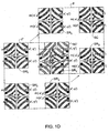
- Fig. 1D there is illustrated a mechanism according to which the characteristic (spiky) MTF mentioned above is formed.
- the MTF and OTF are dependent on auto-correlation of the field distribution in the aperture plane.
- the total field at the aperture plane is Fourier transformed when the light reaches the detector plane and its intensity is captured by the detector. From the Fourier transform properties, the operation of absolute value square over the field point spread function (PSF) obtained in the detector plane is equivalent to auto-correlation operation performed over the Fourier of the fields in the aperture plane.
- PSF field point spread function
- a field F consisting of the symmetrized chirp SC and three replicas SR 1 -SR 3 , substantially overlaps with a replica F' of this field, consisting of the symmetrized chirp SC' and three replicas SR' 1 -SR' 3 , when the field and the replica are shifted for a specific distance with respect to each other.
- replica SC' almost coincides with replica SR 2 . It is seen, that phase distributions between these replicas are highly correlated, because the black and gray lines within replicas are similarly oriented.
- An electric field E generated by the chirp diffracted at the random plate illuminated with the chirp, is dependent not only on the chirp's phase distribution, which due to defocusing is proportional to exp [ iW m (x 2 +y 2 ) ], W m being the amount of defocusing, ( x,y ) being a coordinate system centered at the optical axis OA , but it is also dependent on field transmission function m of the aperture.
- the random plate is a random field transmission plate, and m(x',y') is its field transmission function. As explained above, the mirroring is obtained due to the partially transparent mirrors 16 being perpendicular to the random plate.
- E tot x y A ⁇ E x y + B ⁇ E ⁇ - x , y + C ⁇ E ⁇ - x , - y + D ⁇ E ⁇ x , - y
- OTF x ⁇ y ⁇ ⁇ - ⁇ ⁇ ⁇ - ⁇ ⁇ E tot x y ⁇ E tot * ⁇ x - x ⁇ , y - y ⁇ ⁇ dxdy
- This integral can be presented as a product of auto-correlation of the chirp's field and autocorrelation of the field transmission function m of the aperture in several cases.
- the transparency m can be taken out of the integral when it is random.
- formula (5) can presented as a product of two autocorrelations are known.
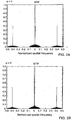
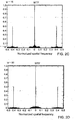
- Figs 2A-2D there are shown examples of an OTF obtained by the inventors as a result of (5) applied for their device. The examples are different in the degree of defocusing: while for Fig. 2A this degree is zero, for Figs 2C-2D it is larger.
- the defocusing factor is as high as 50 in Fig. 2D . Nevertheless, all Figs.
- the device of the invention can be used for achieving also the super resolution, if the detector is used to integrate light intensity while the chirp is scanned.
- moving the random plate to various positions (x 0 ,y 0 ) creates an MTF containing peaks at spatial frequencies corresponding to those positions
- the correspondence through Fourier transform is meant: the positions in the aperture plane are proportional to the spatial frequencies in the detector plane.
- all various spatial frequencies can be obtained.
- the larger the maximum shift from pairs (x 0 ,y 0 ) the larger the obtained super resolution factor. This factor is unlimited, in the sense that any high spatial frequency can be transmitted through an appropriately designed random plane and recovered by scanning.
- the operation of a device of the invention has been simulated by the inventors. Referring to Figs. 3-5 , there the simulation results are presented.
- Figs. 3A-3D there is shown a set of reconstructions of a script image (i.e. of an image containing writing).
- Fig. 3B there is shown the image obtained for the same defocusing ⁇ obtained without applying the inventor's technique.
- Figs. 4A-4D and 5A-5D correspond to the Figs. 3A-3D , but for an imaged object being a resolution target or a baby face, respectively.
- the results presented in Figs. 3-5 are all-optical, because the scanning was simulated to gather all spatial frequencies detected by the detector with appropriate coefficients. No image processing was applied to further enhance images in Figs. 3-5 .
Landscapes
- Physics & Mathematics (AREA)
- General Physics & Mathematics (AREA)
- Optics & Photonics (AREA)
- Holo Graphy (AREA)
- Microscoopes, Condenser (AREA)
- Testing, Inspecting, Measuring Of Stereoscopic Televisions And Televisions (AREA)
- Focusing (AREA)
- Automatic Focus Adjustment (AREA)
- Length Measuring Devices By Optical Means (AREA)
- Eye Examination Apparatus (AREA)
Claims (14)
- Eine optische Anordnung zur Verwendung in der Bildgebung mit einer hohen Tiefenschärfe, wobei die optische Anordnung Folgendes umfasst:eine Blendeneinheit (10), die eine Zufalls-Platte (12) umfasst, ausgebildet als optischer Raumfilter, die eine Zufalls-Übertragungsfunktion des optischen Feldes hat und der optische Leistung fehlt, dadurch gekennzeichnet, dass sie weiter Folgendes umfasst:eine Replikationseinheit (16, 26), die ein optisches Eingabefeld von der Blendeneinheit (10) empfängt und ausgebildet ist, um eine Vielzahl von Nachbildungen (Ri-R3) des optischen Eingabefelds so bereitzustellen, dass die Nachbildungen (Ri-R3) mindestens zwei Nachbildungen (Ri-R3) einschließen, die im Wesentlichen dieselbe Phasenverteilung haben und in verschiedenen Bereichen der Ebene der Blendeneinheit (10) erstellt werden.
- Die optische Anordnung gemäß Anspruch 1, worin die Zufalls-Platte (12) als undurchsichtige Platte mit zufällig verteilten optischen Fenstern ausgebildet ist, die eine zufällige Durchlässigkeits-/Blockade-Verteilung eines optischen Eingabefelds erzeugen.
- Die optische Anordnung gemäß Anspruch 1, worin die Zufalls-Platte(12) als durchsichtige Platte mit zufällig verteilten diffus strahlenden Inseln ausgebildet ist, die eine zufällige Phasenverteilung eines optischen Eingabefelds erzeugen.
- Die optische Anordnung gemäß Anspruch 1, worin die Zufalls-Platte (12) ein zufälliges Lochblendenmuster umfasst.
- Die optische Anordnung gemäß einem beliebigen der Ansprüche 1 bis 4, worin die Replikationseinheit mindestens erste und zweite Symmetriereinheiten (16, 26) umfasst, die ausgebildet sind, um die mindestens zwei Nachbildungen (Ri-R3) des optischen Eingabefeldes bereitzustellen und sequentiell das optische Eingabefeld, das auf die Blendeneinheit (10) projiziert wird, mit Bezug auf das erste beziehungsweise das zweite Symmetriezentrum zu symmetrieren.
- Die optische Anordnung gemäß Anspruch 5, worin die erste Symmetriereinheit (16) ausgebildet ist, um einen Abschnitt eines Chirps (C) des optischen Eingabefeldes zu symmetrieren, das durch die Blendeneinheit (10) dringt, und die zweite Symmetriereinheit (26) zum Symmetrieren einer Ausgabe der ersten Symmetriereinheit (16) ausgebildet ist.
- Die optische Anordnung gemäß Anspruch 5, worin die Blendeneinheit (10) und die ersten und zweiten Symmetriereinheiten (16, 26) so ausgebildet sind, dass mindestens eine der Nachbildungen (Ri-R3) im Verhältnis zur anderen verschiebbar ist.
- Die optische Anordnung gemäß Anspruch 7, die einen Scanner (30) umfasst, ausgebildet und funktionsfähig, um für die Verschiebung mindestens einer der Nachbildungen (Ri-R3) zu sorgen, durch Bereitstellung einer relativen Verschiebung der Blendeneinheit (10) und/oder der ersten Symmetriereinheit (16) im Verhältnis zur zweiten Symmetriereinheit (26).
- Die optische Anordnung gemäß einem beliebigen der Ansprüche 1 bis 4, worin die Replikationseinheit reflektierende Oberflächen umfasst.
- Die optische Anordnung gemäß Anspruch 9, worin die reflektierenden Oberflächen von mindestens ersten und zweiten Reflektoreinheiten gebildet werden, die in einer beabstandeten Beziehung entlang einer optischen Achse der Lichtausbreitung durch die optische Anordnung zu einer Bildgebungsebene hin untergebracht sind.
- Die optische Anordnung gemäß Anspruch 10, worin jede der ersten und der zweiten Reflektoreinheit zwei Reflektoren umfasst, die zueinander senkrechte reflektierende Oberflächen bestimmen, so dass die reflektierende Oberfläche der ersten Reflektoreinheit im Wesentlichen parallel zu der entsprechenden reflektierenden Oberfläche der zweiten Reflektoreinheit ist.
- Die optische Anordnung gemäß einem beliebigen der Ansprüche 1 bis 4, worin die Replikationseinheit mindestens eines von Folgendem umfasst: eine Matrix von optischen Fasern, einen räumlichen Lichtmodulator und ein oder mehrere Eckprismen.
- Die optische Anordnung gemäß einem beliebigen der Ansprüche 1 bis 12, die eine Pixeldetektor-Matrix auf einer Bildgebungsebene umfasst.
- Ein Verfahren zur Verwendung in der Bildgebung zur Bereitstellung von Bildgebung mit einer hohen Tiefenschärfe, wobei das Verfahren Folgendes umfasst: Übertragen eines abzubildenden optischen Eingabefelds durch eine Lochblende, die eine Zufalls-Platte (12) ohne optische Leistung umfasst, dadurch gekennzeichnet, dass es weiter folgenden Schritt umfasst:optische Verarbeitung des optischen Feldes, das durch die Zufalls-Platte (12) übertragen wird, zur Erzeugung einer Vielzahl von Nachbildungen (Ri-R3) des optischen Feldes, so dass die Nachbildungen (Ri-R3) mindestens zwei Nachbildungen (Ri-R3) einschließen, die im Wesentlichen dieselbe Phasenverteilung haben und in verschiedenen Bereichen der Blendenebene erstellt werden.
Applications Claiming Priority (2)
| Application Number | Priority Date | Filing Date | Title |
|---|---|---|---|
| US79322606P | 2006-04-20 | 2006-04-20 | |
| PCT/IL2007/000500 WO2007122616A2 (en) | 2006-04-20 | 2007-04-22 | System and method for imaging with extended depth of focus and incoherent light |
Publications (3)
| Publication Number | Publication Date |
|---|---|
| EP2008143A2 EP2008143A2 (de) | 2008-12-31 |
| EP2008143A4 EP2008143A4 (de) | 2010-06-02 |
| EP2008143B1 true EP2008143B1 (de) | 2012-04-11 |
Family
ID=38625413
Family Applications (1)
| Application Number | Title | Priority Date | Filing Date |
|---|---|---|---|
| EP07736240A Not-in-force EP2008143B1 (de) | 2006-04-20 | 2007-04-22 | System und verfahren für die bildgebung mit erweiterter fokustiefe und nicht kohärentem licht |
Country Status (5)
| Country | Link |
|---|---|
| US (1) | US7936522B2 (de) |
| EP (1) | EP2008143B1 (de) |
| AT (1) | ATE553406T1 (de) |
| ES (1) | ES2387119T3 (de) |
| WO (1) | WO2007122616A2 (de) |
Families Citing this family (5)
| Publication number | Priority date | Publication date | Assignee | Title |
|---|---|---|---|---|
| CN101562701B (zh) * | 2009-03-25 | 2012-05-02 | 北京航空航天大学 | 一种用于光场成像的数字对焦方法及装置 |
| US8531783B2 (en) | 2010-02-09 | 2013-09-10 | Xceed Imaging Ltd. | Imaging method and system for imaging with extended depth of focus |
| TWI588560B (zh) | 2012-04-05 | 2017-06-21 | 布萊恩荷登視覺協會 | 用於屈光不正之鏡片、裝置、方法及系統 |
| US9201250B2 (en) | 2012-10-17 | 2015-12-01 | Brien Holden Vision Institute | Lenses, devices, methods and systems for refractive error |
| EP2908773B1 (de) | 2012-10-17 | 2024-01-03 | Brien Holden Vision Institute | Linsen, vorrichtungen, verfahren und systeme für brechungsfehler |
Family Cites Families (6)
| Publication number | Priority date | Publication date | Assignee | Title |
|---|---|---|---|---|
| US3700895A (en) * | 1969-08-14 | 1972-10-24 | Research Corp | Scatterhole camera and method for using same including the step of convoluting the image |
| JP3395798B2 (ja) * | 1993-12-22 | 2003-04-14 | 株式会社ニコン | 位置検出方法及び装置、並びに露光方法及び装置 |
| US6384949B1 (en) * | 1999-02-25 | 2002-05-07 | Ricoh Company Ltd. | Optical scanning device, image forming apparatus and optical scanning method |
| IL133243A0 (en) * | 1999-03-30 | 2001-03-19 | Univ Ramot | A method and system for super resolution |
| WO2003076984A1 (en) * | 2002-03-14 | 2003-09-18 | Ramot At Tel Aviv University Ltd. | All optical extended depth-of-field imaging system |
| US7061693B2 (en) * | 2004-08-16 | 2006-06-13 | Xceed Imaging Ltd. | Optical method and system for extended depth of focus |
-
2007
- 2007-04-22 AT AT07736240T patent/ATE553406T1/de active
- 2007-04-22 WO PCT/IL2007/000500 patent/WO2007122616A2/en not_active Ceased
- 2007-04-22 ES ES07736240T patent/ES2387119T3/es active Active
- 2007-04-22 EP EP07736240A patent/EP2008143B1/de not_active Not-in-force
-
2008
- 2008-10-20 US US12/254,152 patent/US7936522B2/en active Active
Also Published As
| Publication number | Publication date |
|---|---|
| ATE553406T1 (de) | 2012-04-15 |
| US7936522B2 (en) | 2011-05-03 |
| EP2008143A2 (de) | 2008-12-31 |
| WO2007122616A3 (en) | 2009-04-09 |
| WO2007122616A2 (en) | 2007-11-01 |
| US20090074239A1 (en) | 2009-03-19 |
| ES2387119T3 (es) | 2012-09-14 |
| EP2008143A4 (de) | 2010-06-02 |
Similar Documents
| Publication | Publication Date | Title |
|---|---|---|
| Rosen et al. | Recent advances in self-interference incoherent digital holography | |
| Vijayakumar et al. | Coded aperture correlation holography system with improved performance | |
| Vijayakumar et al. | Interferenceless coded aperture correlation holography–a new technique for recording incoherent digital holograms without two-wave interference | |
| Vijayakumar et al. | Coded aperture correlation holography–a new type of incoherent digital holograms | |
| Rosen et al. | Digital spatially incoherent Fresnel holography | |
| Zhang et al. | Elimination of a zero-order beam induced by a pixelated spatial light modulator for holographic projection | |
| Kashter et al. | Resolving images by blurring: superresolution method with a scattering mask between the observed objects and the hologram recorder | |
| Barlev et al. | Multifunctional binary diffractive optical elements for structured light projectors | |
| Rosen et al. | Fluorescence incoherent color holography | |
| Bulbul et al. | Partial aperture imaging by systems with annular phase coded masks | |
| Francis et al. | Wavelength multiplexed reflection matched spatial filters using LiNbO3 | |
| Camacho et al. | Quantitative phase microscopy using defocusing by means of a spatial light modulator | |
| Anand et al. | Review of engineering techniques in chaotic coded aperture imagers | |
| US20030169505A1 (en) | Shear processor | |
| KR0140533B1 (ko) | 광학 상관기 및 크로스-상관 정보 발생방법 | |
| US7936522B2 (en) | System and method for imaging with extended depth of focus and incoherent light | |
| Hong et al. | Second harmonic generation based joint transform correlator for human face and QR code recognitions | |
| Kumar et al. | Interferenceless coded aperture correlation holography with synthetic point spread holograms | |
| Wernicke et al. | Liquid crystal display as spatial light modulator for diffractive optical elements and the reconstruction of digital holograms | |
| Heifetz et al. | Shift-invariant real-time edge-enhanced VanderLugt correlator using video-rate compatible photorefractive polymer | |
| JPH05501617A (ja) | 位相測定走査形光学顕微鏡 | |
| IL194783A (en) | Imaging system and method with incoherent light and deeper focus | |
| Takaki et al. | Incoherent pattern detection using a liquid-crystal active lens | |
| Putilin et al. | Waveguide holograms in LCD illumination units | |
| RU2458367C2 (ru) | Оптическое устройство с парой дифракционных оптических элементов |
Legal Events
| Date | Code | Title | Description |
|---|---|---|---|
| PUAI | Public reference made under article 153(3) epc to a published international application that has entered the european phase |
Free format text: ORIGINAL CODE: 0009012 |
|
| 17P | Request for examination filed |
Effective date: 20080325 |
|
| AK | Designated contracting states |
Kind code of ref document: A2 Designated state(s): AT BE BG CH CY CZ DE DK EE ES FI FR GB GR HU IE IS IT LI LT LU LV MC MT NL PL PT RO SE SI SK TR |
|
| AX | Request for extension of the european patent |
Extension state: AL BA HR MK RS |
|
| R17D | Deferred search report published (corrected) |
Effective date: 20090409 |
|
| A4 | Supplementary search report drawn up and despatched |
Effective date: 20100503 |
|
| RIC1 | Information provided on ipc code assigned before grant |
Ipc: G02B 27/58 20060101ALI20100426BHEP Ipc: G02B 15/14 20060101AFI20080129BHEP |
|
| GRAP | Despatch of communication of intention to grant a patent |
Free format text: ORIGINAL CODE: EPIDOSNIGR1 |
|
| GRAS | Grant fee paid |
Free format text: ORIGINAL CODE: EPIDOSNIGR3 |
|
| GRAA | (expected) grant |
Free format text: ORIGINAL CODE: 0009210 |
|
| AK | Designated contracting states |
Kind code of ref document: B1 Designated state(s): AT BE BG CH CY CZ DE DK EE ES FI FR GB GR HU IE IS IT LI LT LU LV MC MT NL PL PT RO SE SI SK TR |
|
| DAX | Request for extension of the european patent (deleted) | ||
| REG | Reference to a national code |
Ref country code: GB Ref legal event code: FG4D |
|
| REG | Reference to a national code |
Ref country code: CH Ref legal event code: EP |
|
| REG | Reference to a national code |
Ref country code: AT Ref legal event code: REF Ref document number: 553406 Country of ref document: AT Kind code of ref document: T Effective date: 20120415 |
|
| REG | Reference to a national code |
Ref country code: IE Ref legal event code: FG4D |
|
| REG | Reference to a national code |
Ref country code: DE Ref legal event code: R096 Ref document number: 602007021910 Country of ref document: DE Effective date: 20120614 |
|
| REG | Reference to a national code |
Ref country code: NL Ref legal event code: T3 |
|
| PGFP | Annual fee paid to national office [announced via postgrant information from national office to epo] |
Ref country code: CH Payment date: 20120531 Year of fee payment: 6 |
|
| REG | Reference to a national code |
Ref country code: CH Ref legal event code: NV Representative=s name: MARKS & CLERK (LUXEMBOURG) LLP |
|
| PGFP | Annual fee paid to national office [announced via postgrant information from national office to epo] |
Ref country code: BE Payment date: 20120530 Year of fee payment: 6 |
|
| REG | Reference to a national code |
Ref country code: ES Ref legal event code: FG2A Ref document number: 2387119 Country of ref document: ES Kind code of ref document: T3 Effective date: 20120914 |
|
| LTIE | Lt: invalidation of european patent or patent extension |
Effective date: 20120411 |
|
| PG25 | Lapsed in a contracting state [announced via postgrant information from national office to epo] |
Ref country code: PL Free format text: LAPSE BECAUSE OF FAILURE TO SUBMIT A TRANSLATION OF THE DESCRIPTION OR TO PAY THE FEE WITHIN THE PRESCRIBED TIME-LIMIT Effective date: 20120411 Ref country code: SE Free format text: LAPSE BECAUSE OF FAILURE TO SUBMIT A TRANSLATION OF THE DESCRIPTION OR TO PAY THE FEE WITHIN THE PRESCRIBED TIME-LIMIT Effective date: 20120411 Ref country code: IS Free format text: LAPSE BECAUSE OF FAILURE TO SUBMIT A TRANSLATION OF THE DESCRIPTION OR TO PAY THE FEE WITHIN THE PRESCRIBED TIME-LIMIT Effective date: 20120811 Ref country code: LT Free format text: LAPSE BECAUSE OF FAILURE TO SUBMIT A TRANSLATION OF THE DESCRIPTION OR TO PAY THE FEE WITHIN THE PRESCRIBED TIME-LIMIT Effective date: 20120411 Ref country code: FI Free format text: LAPSE BECAUSE OF FAILURE TO SUBMIT A TRANSLATION OF THE DESCRIPTION OR TO PAY THE FEE WITHIN THE PRESCRIBED TIME-LIMIT Effective date: 20120411 Ref country code: CY Free format text: LAPSE BECAUSE OF FAILURE TO SUBMIT A TRANSLATION OF THE DESCRIPTION OR TO PAY THE FEE WITHIN THE PRESCRIBED TIME-LIMIT Effective date: 20120411 |
|
| PG25 | Lapsed in a contracting state [announced via postgrant information from national office to epo] |
Ref country code: PT Free format text: LAPSE BECAUSE OF FAILURE TO SUBMIT A TRANSLATION OF THE DESCRIPTION OR TO PAY THE FEE WITHIN THE PRESCRIBED TIME-LIMIT Effective date: 20120813 Ref country code: LV Free format text: LAPSE BECAUSE OF FAILURE TO SUBMIT A TRANSLATION OF THE DESCRIPTION OR TO PAY THE FEE WITHIN THE PRESCRIBED TIME-LIMIT Effective date: 20120411 Ref country code: GR Free format text: LAPSE BECAUSE OF FAILURE TO SUBMIT A TRANSLATION OF THE DESCRIPTION OR TO PAY THE FEE WITHIN THE PRESCRIBED TIME-LIMIT Effective date: 20120712 Ref country code: MC Free format text: LAPSE BECAUSE OF NON-PAYMENT OF DUE FEES Effective date: 20120430 Ref country code: SI Free format text: LAPSE BECAUSE OF FAILURE TO SUBMIT A TRANSLATION OF THE DESCRIPTION OR TO PAY THE FEE WITHIN THE PRESCRIBED TIME-LIMIT Effective date: 20120411 |
|
| PGFP | Annual fee paid to national office [announced via postgrant information from national office to epo] |
Ref country code: IT Payment date: 20120522 Year of fee payment: 6 |
|
| REG | Reference to a national code |
Ref country code: IE Ref legal event code: MM4A |
|
| PG25 | Lapsed in a contracting state [announced via postgrant information from national office to epo] |
Ref country code: EE Free format text: LAPSE BECAUSE OF FAILURE TO SUBMIT A TRANSLATION OF THE DESCRIPTION OR TO PAY THE FEE WITHIN THE PRESCRIBED TIME-LIMIT Effective date: 20120411 Ref country code: CZ Free format text: LAPSE BECAUSE OF FAILURE TO SUBMIT A TRANSLATION OF THE DESCRIPTION OR TO PAY THE FEE WITHIN THE PRESCRIBED TIME-LIMIT Effective date: 20120411 Ref country code: DK Free format text: LAPSE BECAUSE OF FAILURE TO SUBMIT A TRANSLATION OF THE DESCRIPTION OR TO PAY THE FEE WITHIN THE PRESCRIBED TIME-LIMIT Effective date: 20120411 Ref country code: SK Free format text: LAPSE BECAUSE OF FAILURE TO SUBMIT A TRANSLATION OF THE DESCRIPTION OR TO PAY THE FEE WITHIN THE PRESCRIBED TIME-LIMIT Effective date: 20120411 Ref country code: RO Free format text: LAPSE BECAUSE OF FAILURE TO SUBMIT A TRANSLATION OF THE DESCRIPTION OR TO PAY THE FEE WITHIN THE PRESCRIBED TIME-LIMIT Effective date: 20120411 Ref country code: IE Free format text: LAPSE BECAUSE OF NON-PAYMENT OF DUE FEES Effective date: 20120422 |
|
| PLBE | No opposition filed within time limit |
Free format text: ORIGINAL CODE: 0009261 |
|
| STAA | Information on the status of an ep patent application or granted ep patent |
Free format text: STATUS: NO OPPOSITION FILED WITHIN TIME LIMIT |
|
| 26N | No opposition filed |
Effective date: 20130114 |
|
| PGFP | Annual fee paid to national office [announced via postgrant information from national office to epo] |
Ref country code: AT Payment date: 20120529 Year of fee payment: 6 |
|
| REG | Reference to a national code |
Ref country code: DE Ref legal event code: R097 Ref document number: 602007021910 Country of ref document: DE Effective date: 20130114 |
|
| PG25 | Lapsed in a contracting state [announced via postgrant information from national office to epo] |
Ref country code: MT Free format text: LAPSE BECAUSE OF FAILURE TO SUBMIT A TRANSLATION OF THE DESCRIPTION OR TO PAY THE FEE WITHIN THE PRESCRIBED TIME-LIMIT Effective date: 20120411 Ref country code: BG Free format text: LAPSE BECAUSE OF FAILURE TO SUBMIT A TRANSLATION OF THE DESCRIPTION OR TO PAY THE FEE WITHIN THE PRESCRIBED TIME-LIMIT Effective date: 20120711 |
|
| BERE | Be: lapsed |
Owner name: XCEED IMAGING LTD. Effective date: 20130430 |
|
| REG | Reference to a national code |
Ref country code: CH Ref legal event code: PL |
|
| REG | Reference to a national code |
Ref country code: AT Ref legal event code: MM01 Ref document number: 553406 Country of ref document: AT Kind code of ref document: T Effective date: 20130430 |
|
| PG25 | Lapsed in a contracting state [announced via postgrant information from national office to epo] |
Ref country code: LI Free format text: LAPSE BECAUSE OF NON-PAYMENT OF DUE FEES Effective date: 20130430 Ref country code: AT Free format text: LAPSE BECAUSE OF NON-PAYMENT OF DUE FEES Effective date: 20130430 Ref country code: BE Free format text: LAPSE BECAUSE OF NON-PAYMENT OF DUE FEES Effective date: 20130430 Ref country code: CH Free format text: LAPSE BECAUSE OF NON-PAYMENT OF DUE FEES Effective date: 20130430 |
|
| PG25 | Lapsed in a contracting state [announced via postgrant information from national office to epo] |
Ref country code: IT Free format text: LAPSE BECAUSE OF NON-PAYMENT OF DUE FEES Effective date: 20130422 |
|
| PG25 | Lapsed in a contracting state [announced via postgrant information from national office to epo] |
Ref country code: TR Free format text: LAPSE BECAUSE OF FAILURE TO SUBMIT A TRANSLATION OF THE DESCRIPTION OR TO PAY THE FEE WITHIN THE PRESCRIBED TIME-LIMIT Effective date: 20120411 |
|
| PG25 | Lapsed in a contracting state [announced via postgrant information from national office to epo] |
Ref country code: LU Free format text: LAPSE BECAUSE OF NON-PAYMENT OF DUE FEES Effective date: 20120422 |
|
| PG25 | Lapsed in a contracting state [announced via postgrant information from national office to epo] |
Ref country code: HU Free format text: LAPSE BECAUSE OF FAILURE TO SUBMIT A TRANSLATION OF THE DESCRIPTION OR TO PAY THE FEE WITHIN THE PRESCRIBED TIME-LIMIT Effective date: 20070422 |
|
| REG | Reference to a national code |
Ref country code: FR Ref legal event code: PLFP Year of fee payment: 10 |
|
| PGFP | Annual fee paid to national office [announced via postgrant information from national office to epo] |
Ref country code: NL Payment date: 20160420 Year of fee payment: 10 |
|
| PGFP | Annual fee paid to national office [announced via postgrant information from national office to epo] |
Ref country code: GB Payment date: 20160421 Year of fee payment: 10 Ref country code: ES Payment date: 20160413 Year of fee payment: 10 Ref country code: DE Payment date: 20160421 Year of fee payment: 10 |
|
| PGFP | Annual fee paid to national office [announced via postgrant information from national office to epo] |
Ref country code: FR Payment date: 20160421 Year of fee payment: 10 |
|
| REG | Reference to a national code |
Ref country code: DE Ref legal event code: R119 Ref document number: 602007021910 Country of ref document: DE |
|
| REG | Reference to a national code |
Ref country code: NL Ref legal event code: MM Effective date: 20170501 |
|
| GBPC | Gb: european patent ceased through non-payment of renewal fee |
Effective date: 20170422 |
|
| REG | Reference to a national code |
Ref country code: FR Ref legal event code: ST Effective date: 20171229 |
|
| PG25 | Lapsed in a contracting state [announced via postgrant information from national office to epo] |
Ref country code: NL Free format text: LAPSE BECAUSE OF NON-PAYMENT OF DUE FEES Effective date: 20170501 Ref country code: FR Free format text: LAPSE BECAUSE OF NON-PAYMENT OF DUE FEES Effective date: 20170502 Ref country code: DE Free format text: LAPSE BECAUSE OF NON-PAYMENT OF DUE FEES Effective date: 20171103 |
|
| PG25 | Lapsed in a contracting state [announced via postgrant information from national office to epo] |
Ref country code: GB Free format text: LAPSE BECAUSE OF NON-PAYMENT OF DUE FEES Effective date: 20170422 |
|
| REG | Reference to a national code |
Ref country code: ES Ref legal event code: FD2A Effective date: 20180625 |
|
| PG25 | Lapsed in a contracting state [announced via postgrant information from national office to epo] |
Ref country code: ES Free format text: LAPSE BECAUSE OF NON-PAYMENT OF DUE FEES Effective date: 20170423 |