EP2008512A1 - Procédé et dispositif destinés à brosser des animaux - Google Patents
Procédé et dispositif destinés à brosser des animaux Download PDFInfo
- Publication number
- EP2008512A1 EP2008512A1 EP08011408A EP08011408A EP2008512A1 EP 2008512 A1 EP2008512 A1 EP 2008512A1 EP 08011408 A EP08011408 A EP 08011408A EP 08011408 A EP08011408 A EP 08011408A EP 2008512 A1 EP2008512 A1 EP 2008512A1
- Authority
- EP
- European Patent Office
- Prior art keywords
- sensors
- sensor
- monitoring
- brush
- brushing device
- Prior art date
- Legal status (The legal status is an assumption and is not a legal conclusion. Google has not performed a legal analysis and makes no representation as to the accuracy of the status listed.)
- Withdrawn
Links
Images
Classifications
-
- A—HUMAN NECESSITIES
- A01—AGRICULTURE; FORESTRY; ANIMAL HUSBANDRY; HUNTING; TRAPPING; FISHING
- A01K—ANIMAL HUSBANDRY; AVICULTURE; APICULTURE; PISCICULTURE; FISHING; REARING OR BREEDING ANIMALS, NOT OTHERWISE PROVIDED FOR; NEW BREEDS OF ANIMALS
- A01K13/00—Devices for grooming or caring of animals, e.g. curry-combs; Fetlock rings; Tail-holders; Devices for preventing crib-biting; Washing devices; Protection against weather conditions or insects
- A01K13/004—Rubbing posts
Definitions
- the invention is directed to a method and a device for brushing animals, in particular pigs, with at least one rotating brush, which is motor-driven / are.
- a cattle cleaning device comprising a support frame with a parallelogram frame construction, with a reciprocally pivotable leg, are attached to the two mutually at a predetermined angle, rotatably mounted, driven by a motor device and provided with bristles rollers.
- the parallelogram frame construction is provided with at least one spring, one end of which is fixed to the support frame and the other end to the leg.
- a contactor is provided, which can be contacted by a contact element fastened to the leg.
- a timer device is provided, which switches off the motor device after a predetermined period of time. Even with this arrangement, the brushes are only set in rotation as soon as a cattle is placed under the brushes and raises the reciprocable leg, whereby the contact is closed and turns on the motor for a predetermined period of time.
- the brush (s) remain switched on (-en) until at least a predetermined period of time has elapsed.
- the beginning of this waiting time period can be set to the switch-on time of the device, so that the switched-on device can not be switched off immediately.
- short pauses in the sensor output signal - for example, if the animal temporarily vertiarrt motionless - bridged; it will be one Hysteresis created, inter alia, prevents an animal standing in the vicinity of the device shortly after each other triggers repetitive switching on and off of the device.
- the rotational movement of the rotating brush (s) is not interpreted as movement. This measure is very important because otherwise the rotating brushes themselves would erroneously be considered as moving animals and would continue to operate endlessly. Since the individual bristles of the rotating brushes are very thin, it is possible to compare the sensor output signal originating therefrom with a threshold which lies above the sensor output signal representing the rotating brushes. Possibly. Also, one or more sensors may be arranged such that the brushes are located at the edge of the area monitored by them.
- the area to be monitored is limited to the vicinity of the brush or a part thereof; in particular by comparing the output signal (s) of one or more sensors with at least one predetermined limit value and / or by using one or more sensors with directional characteristics.
- a limited area is monitored whose boundaries do not move with respect to the brush rotation axis (s).
- a swing of a movably suspended brushing device, in particular a ringing of the same is not interpreted as a movement, so that further errors are avoided.
- a limited area is monitored, which is limited to a cutout or sector around the brushing device. Not the entire environment of the brushing device must be uniformly monitored unidirectionally. A Due to its weight, brushing device is almost always mounted on a wall of a stable or the like for static reasons, so that the area behind its mounting device (the wall) can not be monitored because no animal can approach it from there anyway. Moreover, such monitoring could possibly cause errors, namely if the lifting and lowering or (re) oscillation of the brushing device itself was interpreted as a movement.
- the maximum extent or range is equal to or less than 1.20 m, preferably equal to or less than 1.10 m, in particular equal or Less than 1 m, because the axis-parallel longitudinal extent of a brush is usually smaller or approximately equal to such a dimension.
- Monitoring is optimal if only or exactly one area is monitored, which is located below a brush and protrudes laterally by about 60 cm laterally over their vertically downwardly cast shadow, preferably by a maximum of 45 cm, in particular by a maximum of 30 cm. Since, in particular, in a pigsty, the space is often a bit cramped and the animals can not go too far from the brushing device, the device should be able to already at a distance of about 30 to To tolerate 60 cm from the brush animals without moving the brushing device in motion.
- the brush diameter is usually not more than about 50 cm, it is sufficient to provide about 1.0 m for the maximum reach of the monitored area in a direction perpendicular to a plane defined by the rotation axis (s) of the brush (s). preferably 0.9 m or less, in particular 0.8 m or less.
- the above boundary conditions can easily be realized by monitoring only a limited area, which has approximately the shape of a sector cut out of a rotation body, for example of a sphere or of a (thick) disc.
- a discus-shaped shape of the monitored sector is preferable, corresponding to its elliptical cross-section adapted to the shape of the brushes.
- the intermediate angle between two brushes is usually on the order of about 90 °; usually it is a bit bigger, maybe 100 ° to 110 °. Since only the brushes are to be protected and monitored, the surveillance area can be limited accordingly. In general, it is even sufficient to monitor only an area which covers within its plane of symmetry a circular sector of at most 90 °, preferably of at most 80 °, in particular of at most 70 °, because the upper area of the brush with an approximately horizontally oriented axis of rotation lies outside anyway The range of the animals to be brushed and must therefore not be monitored.
- one or more non-contact sensors should be used to prevent injury to animals caused by mechanical probes.
- light beams are emitted and received, preferably by means of one or more light barriers, in particular by means of one or more laser sensors.
- the bottom beneath the brushing device could be covered with stainless steel or a similar, reflective material, so that a light or laser beam can be directed onto it, which is reflected in the absence of an animal to be brushed, in the presence of an animal to be brushed Not.
- electromagnetic waves are used to monitor an environment of the brushing device emitted and received, in particular by means of radar sensors. This allows three-dimensional rooms monitor, similar to door opener sensors.
- a further modified embodiment of the invention is characterized in that acoustic signals are transmitted and received for monitoring an environment of the brushing device, in particular by means of ultrasonic sensors.
- This principle which corresponds to the sense of orientation of bats, also allows monitoring of three-dimensional areas.
- a rather passive sensor method is to detect heat rays for monitoring an environment of the brushing device, in particular by means of thermal sensors.
- the body heat of animals can be recognized. It is also possible to monitor three-dimensional areas.
- the sensors are usually arranged in the vicinity of the axes of rotation of the brushes, so that these axes of rotation strive approximately radially away from the sensor (s).
- the bristles of the rotating brushes move on circular paths around the axes of rotation, their distance to a sensor does not change. This provides the ability to use sensors that detect objects only when their radial distance to the sensor changes. Such sensors then do not perceive the bristles rotating about radial rays.
- Sensors are, for example, certain radar sensors, which (only) work with evaluation of the Doppler frequency, which arises during the approach / removal of objects.
- the output signals of several sensors can be superimposed, in particular added.
- a space with a maximum range can be monitored overall within or along the brush plane, while the rotational movement of the brushes is only slightly perceived.
- the superimposed outputs of several sensors should be compared to a threshold to distinguish movements within the monitored range of movements outside the monitored area.
- the threshold value can possibly be adjustable, so that consideration can be given to the local conditions, in particular the size of the stall or gate, when installing a brushing device according to the invention.
- a device according to the invention for brushing animals, in particular pigs, with at least one rotating brush which can be driven by a motor is characterized by a device for monitoring a spatially limited environment of the brush (s) with regard to presence and / or on movements of objects not belonging to the brushing device, and for switching on the brush (s) upon detection of such movement or approach within the monitored area.
- At least one non-contact sensor for monitoring an environment of the brushing device with regard to movements and / or the approach of objects not belonging to the brushing device.
- Such sensors unlike mechanical feelers, are not perceived by the animals at all and therefore can not be bypassed; There is also no risk of injury to animals.
- Suitable sensors are optical sensors, preferably with a light source for emitting light waves, in particular beams, and a light-sensitive element for receiving light waves, in particular beams, preferably in the manner of a light barrier, in particular in the manner of a laser sensor.
- electromagnetic sensors preferably with an antenna for emitting electromagnetic waves and with an antenna for receiving electromagnetic waves, in particular in the manner of a radar sensor.
- acoustic sensors preferably with an electro-acoustic transducer for emitting acoustic waves, in particular a loudspeaker, and with a microphone for receiving acoustic waves, in particular in the manner of an ultrasonic sensor.
- Another variant is the use of one or more thermal sensors, with a heat-sensitive element for receiving thermal radiation, in particular in the manner of an infrared sensor.
- sensors which operate according to different physical principles, for example a radar sensor for remote monitoring of the brush ends and a light barrier for detecting animals that remain immobile under the brushing device.
- - as the invention also provides - the brush (s) and drive is arranged on a height-adjustable brush head / are, so the brushing of animals with different body size is possible.
- at least one monitoring sensor can be arranged on the height-adjustable brush head. There, the lifting movement or also a (subsequent) oscillation of the brush head is not perceived by the sensor.
- a preferred embodiment of the invention comprises two brushes, wherein the axis of rotation of a brush is approximately perpendicular, the axis of rotation of the other brush approximately horizontal or slightly rising from the brush head.
- the axes of rotation of both brushes are preferably approximately in a common, vertical plane and intersect approximately in the region of the brush head, so that there on the one hand there is the possibility to couple both brushes to a common drive motor, for example.
- the drive shafts of the two brushes in the region of the intersection the two axes of rotation are connected to a respective output shaft of a branching and / or reduction gear, to whose input shaft a motor is connected, in particular an electric motor.
- At least one monitoring sensor should have a directional receiving pattern for monitoring a limited sector so that insubstantial areas of the brushing device's environment are excluded from monitoring and thus can not cause malfunction.
- a plurality of monitoring sensors in particular those with a directed reception diagram, can be arranged in such a way that they monitor different parts of the surroundings of the brushing device at least in regions.
- the monitoring area can be increased and adapted exactly to the geometry of the brushing device.
- the invention recommends to use at least two monitoring sensors, which are arranged on both sides, in particular symmetrically to, a vertical plane spanned by the / the brush rotation axis (s). This can be realized in a particularly simple way by arranging at least two monitoring sensors lying opposite one another on each flat side of the brush head, while the brush (s) is mounted on the brush head in the area (one) of the end face lying between these flat sides. are.
- At least two monitoring sensors should be arranged such that their main reception axes are arranged symmetrically to a vertical plane spanned by the brush rotation axis (s). This accommodates the symmetry of the brushing device with respect to a vertical plane defined by the brush rotation axes, and achieves symmetrical monitoring in both directions.
- At least two monitoring sensors can be arranged such that their main receiving axes are approximately or nearly parallel to each other or slightly diverge from each other, for example. At an angle of not more than 45 °, preferably 30 ° or less, in particular 15 ° or less, however, the main receiving axes should not be coaxial and in particular not antiparallel to one another.
- the outputs of several monitoring sensors can be connected to a module for superimposing the output signals of several monitoring sensors, in particular an adder. At its output one always receives a signal, regardless of which monitoring sensor has detected a movement or presence of a foreign object.
- the optionally superimposed output signals of the monitoring sensors are supplied to a module for comparing at least one output signal of one or more monitoring sensors, or one possibly formed by superimposing a plurality of sensor output signals, with a predetermined limit or threshold, in particular one Comparator.
- a predetermined limit or threshold in particular one Comparator.
- the limit or threshold value can optionally be configured adjustable, for example by means of a potentiometer or by software, so that the responsiveness can be adapted to the respective local conditions.
- a switch-off delay can be generated in the manner of a hysteresis, so that an unstable switching state a quick swing between switching off and on is avoided.
- the teaching of the invention corresponds to a switching element for switching on and off an electric motor for driving at least one brush, which is coupled to the output signal of at least one monitoring sensor, preferably via a comparator and / or a timer.
- a switching element in particular relays, thus amplifies the low-energy control signal to an energy level sufficient for operating the drive motor.
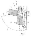
- the most striking components of the device 1 for brushing animals according to the invention are the two cylindrical brushes 2, 3. Both brushes 2, 3 rotate about their respective axis of rotation 4, 5.
- the axis of rotation 4 of a brush 2 extends approximately vertically.
- This axis 4 is cut in its upper region above the brush 2 of the rotation axis 5 of the other brush 3.
- the intermediate angle is about 100 °, such that the second axis of rotation 5 is approximately horizontal or starting from the intersection point 6 easily increases.
- the intermediate angle is determined by the geometry of a branching gear 7, of which two output shafts leads vertically downwards and the axis of rotation 4 of the vertical brush 2 corresponds, while the other output shaft slightly rising from the gear housing and with the approximately horizontal axis of rotation 5 of the other brush 3 is aligned.
- the point of intersection 6 between the two axes of rotation 4, 5 lies in the region of the transmission 7.
- the drive motor 8 preferably an electric motor.
- a mounting plate 9 is fixed, in particular screwed.
- the planes of the mounting plates 9 are oriented vertically and also parallel to each other and parallel to that vertical plane of symmetry, which is spanned by the two intersecting axes of rotation 4, 5 of the brushes 2, 3.
- the base surface of the mounting plates 9 is preferably rectangular in each case, wherein the respective longer side preferably extends in the horizontal direction and projecting beyond that side of the transmission 7 which faces away from the brush 3 with an approximately horizontal axis of rotation 5.
- a support or angle iron 10 is welded, extending approximately parallel to the approximately vertical axis of rotation 4, for the most part down.
- These two parts 9, 10 form a movable, i.e., height-adjustable chassis 11.
- a stationary chassis 12 comprises at least one approximately vertical angle iron 13, in the present example, two of which, by one or preferably two horizontally extending angle iron to a rigid in itself Frame are connected together.
- This (s) angle iron 13 is / are screwed or screwed to a wall 14 with screws 15.
- a respective parallel, i.e., likewise vertical, U-profile is fixed, for example welded, in its lower region, in such a way that the open longitudinal sides of these two U-profiles face one another.
- the remaining between the two U-profiles slot therefore has an undercut geometry.
- a comparable construction is obtained if a square tube is used with a longitudinal slot instead of one or both U-profiles.
- a fixed chassis 12 facing extension 16 is provided, which projects approximately horizontally.
- this extension 16 carries two pointing in opposite directions, aligned pins, so that the construction of the extension 16 on the one hand and the two pins on the other hand has approximately the shape of a T.
- Each pin engages in the undercut of each U-profile.
- the cylindrical, i.e., circular, circular pins permit pivoting of the height-adjustable chassis member 11 relative to the stationary chassis member 12.
- each chassis part 11, 12 there is a respective pivot axis 18, 19.
- These two pivot axes 18, 19 are parallel to each other and extend approximately perpendicular to the of the two axes of rotation 4, 5 of the brushes 2, 3 plane spanned.
- the two pivot axes 18, 19 are mounted in one or two eyes, which are in (each) an angle iron 10, 13 of the respective chassis (frame) 11, 12 are provided.
- the two are connected Swivel axes 18, 19 by a straight elongated plate 20 or strut, which is welded to the two axes 18, 19. This construction allows the upper part of the height-adjustable chassis part 11 to pivot about the stationary axle 19.
- This pivoting angle in turn is bounded above by a stop 21 in the form of a hard rubber part, which is fixed to the stationary chassis 12 and at the upper end point of the permissible pivoting movement in contact with the connecting plate 20 occurs.
- a stop 21 in the form of a hard rubber part, which is fixed to the stationary chassis 12 and at the upper end point of the permissible pivoting movement in contact with the connecting plate 20 occurs.
- an angle iron or sheet 22 is welded, with two legs and an intermediate edge which is parallel to the two pivot axes 18, 19. While the two legs are welded with their free ends or edges on the underside of the connecting plate 20 and / or on one or both pivot axes 18, 19, the intermediate edge extends at a distance from the connecting plate 20.
- At the lower leg is a lower side another stop provided in the form of a second hard rubber part.
- the brushes 2, 3 are optimally aligned for each animal - in smaller animals, the vertical brush rotation axis 4 remains almost vertical, in larger animals, the lower part back to the upper part, corresponding to the then larger waist circumference in relation to the back, and at very large animals, where mainly the upper parts of the body are brushed, the lower brush 2 is again approximately vertical.
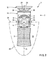
- a respective sensor 24 is arranged on the movable brush head 2-11 on both sides of the plane of symmetry 23.
- This may be a non-contact sensor, which responds at least in the approach of animals, for example.
- the output signals of both sensors 24 are fed to a control device which is also located on the movable brush head 2-11 and contains at least one switching element which is looped into the electrical connection of the drive motor 8 to the power supply and controls the operating state of the drive motor 8 by its switching state ,
- a block for superimposing the output signals of the two sensors 24 This may be a summer, the voltage summed up the two output signals, or else an OR gate, which logical output signals ofndelsmeidern according to the OR function linked together.
- the control unit further includes a comparator, which analog output signals of the two sensors 24 are compared with an optionally adjustable threshold to limit the (common) monitored by the sensors 24 area 25 and mask weak signals, which originate from greater distances.
- a switch-off delay is provided to switch off the switching element and thus the drive motor 8 delayed and not simultaneously with the elimination of the sensor output signals.
- the cut surfaces 26 and 28 are directed radially toward the center of the disk. This center is located centrally between the two sensors 24. In truth, these boundary surfaces 26, 28 are probably not flat, but curved and go without kinks in the curved interface 29 of the monitored area 25, which in Fig. 2 is shown. This interface 29 defines the cross-section through this monitoring disc, which has approximately the shape of a half ellipse.
- the monitored area 25 completely comprises the space between the two brushes 2, 3 as well as the respective mutually facing areas or halves of the brushes 2, 3 in each case to a large extent. Laterally, the disk-sector-shaped, monitored area 25 protrudes beyond the circumference of both brushes 2, 3, so that animals, in particular pigs, have no opportunity to unnoticeably reach one of the brushes 2, 3 and to nibble it.
- the two sensors 24 are located in the vicinity of the point of intersection 6 of the two brush rotation axes 4, 5, preferably less changes Distance between a bristle and the sensors 24 hardly in the rotation of the brushes 2.3.
Landscapes
- Life Sciences & Earth Sciences (AREA)
- Environmental Sciences (AREA)
- Zoology (AREA)
- Animal Husbandry (AREA)
- Biodiversity & Conservation Biology (AREA)
- Catching Or Destruction (AREA)
- Cleaning In General (AREA)
Applications Claiming Priority (1)
| Application Number | Priority Date | Filing Date | Title |
|---|---|---|---|
| DE200710029555 DE102007029555B4 (de) | 2007-06-26 | 2007-06-26 | Verfahren und Vorrichtung zum Bürsten von Tieren |
Publications (1)
| Publication Number | Publication Date |
|---|---|
| EP2008512A1 true EP2008512A1 (fr) | 2008-12-31 |
Family
ID=39862984
Family Applications (1)
| Application Number | Title | Priority Date | Filing Date |
|---|---|---|---|
| EP08011408A Withdrawn EP2008512A1 (fr) | 2007-06-26 | 2008-06-24 | Procédé et dispositif destinés à brosser des animaux |
Country Status (2)
| Country | Link |
|---|---|
| EP (1) | EP2008512A1 (fr) |
| DE (1) | DE102007029555B4 (fr) |
Cited By (7)
| Publication number | Priority date | Publication date | Assignee | Title |
|---|---|---|---|---|
| CN102630595A (zh) * | 2012-05-11 | 2012-08-15 | 郑州牧业工程高等专科学校 | 自动牛体按摩刷 |
| CN104304063A (zh) * | 2014-10-14 | 2015-01-28 | 陈菊芳 | 一种自适应奶牛洗澡机 |
| US9565834B2 (en) | 2012-05-23 | 2017-02-14 | Delaval Holding Ab | Animal brushing arrangement and method of operating animal brushing arrangement |
| US11083171B1 (en) | 2021-03-03 | 2021-08-10 | Ron D. Brooks | Animal operated brushing stand |
| EP3981247A1 (fr) * | 2020-10-07 | 2022-04-13 | Baß Antriebstechnik GmbH | Dispositif pour brosser les animaux |
| WO2022242804A1 (fr) * | 2021-05-19 | 2022-11-24 | LE commerce GmbH | Dispositif de toilettage d'animaux, en particulier de chats domestiques |
| EP4162795A1 (fr) * | 2021-10-05 | 2023-04-12 | Baß Antriebstechnik GmbH | Dispositif pour brosser des animaux |
Families Citing this family (1)
| Publication number | Priority date | Publication date | Assignee | Title |
|---|---|---|---|---|
| CN113424777B (zh) * | 2021-05-18 | 2024-04-05 | 宿州市草源牧业股份有限公司 | 一种奶牛洗浴设备 |
Citations (8)
| Publication number | Priority date | Publication date | Assignee | Title |
|---|---|---|---|---|
| US3175537A (en) * | 1963-05-13 | 1965-03-30 | Milton A Paul | Apparatus for grooming and applying insecticide to an animal |
| JPH07309215A (ja) * | 1994-05-13 | 1995-11-28 | Mk Seiko Co Ltd | 洗車機 |
| DE19734289C1 (de) * | 1997-08-08 | 1998-11-26 | Georg Mayer | Viehputzmaschine |
| DE29920257U1 (de) * | 1999-11-18 | 2000-04-27 | Schurr, Hubert, 88524 Uttenweiler | Rinder-Reinigungs- und Massage-Vorrichtung |
| US20030209209A1 (en) * | 2002-05-10 | 2003-11-13 | Udelle Steven D. | Automated animal self-grooming device |
| DE102004040250B3 (de) * | 2004-08-19 | 2005-10-13 | Schurr Gerätebau GmbH | Kombinierte Reinigungs- und Besprenkelungs- Vorrichtung für Rinder und andere Huftiere |
| DE102004030234B3 (de) | 2004-06-23 | 2005-10-13 | Schurr Gerätebau | Vorrichtung zum Reinigen von Huftieren |
| DE102006012261B3 (de) | 2006-03-15 | 2007-10-04 | Baß Antriebstechnik GmbH | Vorrichtung zum Bürsten von Tieren |
-
2007
- 2007-06-26 DE DE200710029555 patent/DE102007029555B4/de not_active Expired - Fee Related
-
2008
- 2008-06-24 EP EP08011408A patent/EP2008512A1/fr not_active Withdrawn
Patent Citations (9)
| Publication number | Priority date | Publication date | Assignee | Title |
|---|---|---|---|---|
| US3175537A (en) * | 1963-05-13 | 1965-03-30 | Milton A Paul | Apparatus for grooming and applying insecticide to an animal |
| JPH07309215A (ja) * | 1994-05-13 | 1995-11-28 | Mk Seiko Co Ltd | 洗車機 |
| DE19734289C1 (de) * | 1997-08-08 | 1998-11-26 | Georg Mayer | Viehputzmaschine |
| DE29920257U1 (de) * | 1999-11-18 | 2000-04-27 | Schurr, Hubert, 88524 Uttenweiler | Rinder-Reinigungs- und Massage-Vorrichtung |
| DE10002688A1 (de) | 1999-11-18 | 2001-05-31 | Hubert Schurr | Rinder-Reinigungs-Vorrichtung |
| US20030209209A1 (en) * | 2002-05-10 | 2003-11-13 | Udelle Steven D. | Automated animal self-grooming device |
| DE102004030234B3 (de) | 2004-06-23 | 2005-10-13 | Schurr Gerätebau | Vorrichtung zum Reinigen von Huftieren |
| DE102004040250B3 (de) * | 2004-08-19 | 2005-10-13 | Schurr Gerätebau GmbH | Kombinierte Reinigungs- und Besprenkelungs- Vorrichtung für Rinder und andere Huftiere |
| DE102006012261B3 (de) | 2006-03-15 | 2007-10-04 | Baß Antriebstechnik GmbH | Vorrichtung zum Bürsten von Tieren |
Cited By (8)
| Publication number | Priority date | Publication date | Assignee | Title |
|---|---|---|---|---|
| CN102630595A (zh) * | 2012-05-11 | 2012-08-15 | 郑州牧业工程高等专科学校 | 自动牛体按摩刷 |
| US9565834B2 (en) | 2012-05-23 | 2017-02-14 | Delaval Holding Ab | Animal brushing arrangement and method of operating animal brushing arrangement |
| CN104304063A (zh) * | 2014-10-14 | 2015-01-28 | 陈菊芳 | 一种自适应奶牛洗澡机 |
| CN104304063B (zh) * | 2014-10-14 | 2017-01-18 | 陈菊芳 | 一种自适应奶牛洗澡机 |
| EP3981247A1 (fr) * | 2020-10-07 | 2022-04-13 | Baß Antriebstechnik GmbH | Dispositif pour brosser les animaux |
| US11083171B1 (en) | 2021-03-03 | 2021-08-10 | Ron D. Brooks | Animal operated brushing stand |
| WO2022242804A1 (fr) * | 2021-05-19 | 2022-11-24 | LE commerce GmbH | Dispositif de toilettage d'animaux, en particulier de chats domestiques |
| EP4162795A1 (fr) * | 2021-10-05 | 2023-04-12 | Baß Antriebstechnik GmbH | Dispositif pour brosser des animaux |
Also Published As
| Publication number | Publication date |
|---|---|
| DE102007029555A1 (de) | 2009-01-15 |
| DE102007029555B4 (de) | 2009-04-09 |
Similar Documents
| Publication | Publication Date | Title |
|---|---|---|
| EP2008512A1 (fr) | Procédé et dispositif destinés à brosser des animaux | |
| DE202007009018U1 (de) | Vorrichtung zum Bürsten von Tieren | |
| DE69804253T2 (de) | Verbesserungen bei beweglichen robotern und bei ihren steuerungssystemen | |
| DE10158533B4 (de) | Motorgetriebenes System zum Betätigen einer Hecktür eines Kraftfahrzeuges | |
| DE202014000309U1 (de) | Systeme zum Bewegen eines Hubwagens und zum Anheben einer Last | |
| US20140090607A1 (en) | Apparatus for brushing cattle | |
| EP2621269B1 (fr) | Dispositif pour effrayer les oiseaux au moyen d'ondes acoustiques | |
| DE102008032216A1 (de) | Vorrichtung zur Erkennung der Anwesenheit eines Objekts im Raum | |
| EP3581747B1 (fr) | Dispositif de surveillance | |
| DE102021206645B4 (de) | Mobiles Bodenreinigungsgerät sowie Verfahren zum Betreiben desselben | |
| DE102019131774A1 (de) | Überwachungssystem für Roboter und Robotersystem | |
| DE202012007164U1 (de) | Vorrichtung zum Bürsten von Tieren | |
| EP3626052B1 (fr) | Installation de déplacement, en particulier racleur d'enlèvement du fumier, pour une stable | |
| DE202016102264U1 (de) | Massage- und Reinigungs-Vorrichtung für Pferde, Kühe und andere Tiere | |
| DE3344576C1 (de) | Sensoranordnung zur Überwachung des Schwenkbereiches von Türflügeln | |
| DE102015122984A1 (de) | Rückfahrkameraeinrichtung für Kraftfahrzeuge | |
| DE4415401C1 (de) | Vorrichtung zur Überwachung von motorisch angetriebenen Drehflügeltüren | |
| DE69218391T2 (de) | Sicherungssystem für automatische türen | |
| EP3165958A1 (fr) | Dispositif scanner | |
| EP3032289B1 (fr) | Système de grille lumineuse | |
| WO2019162355A1 (fr) | Engin de traitement du sol, en particulier engin de nettoyage du sol | |
| DE102017010781B3 (de) | Tierpflege- und/oder Reinigungseinrichtung | |
| DE202022105301U1 (de) | Vorrichtung zum Betreiben eines Drehtors | |
| WO2022179698A1 (fr) | Procédé pour déterminer une distance minimale entre un objet et une surface d'appareil, dispositif de sécurité pour un appareil de manutention ayant une surface d'appareil, et appareil de manutention | |
| DE102020102576A1 (de) | Vorrichtung zur Erfassung der Position und/oder Geschwindigkeit von Objekten im Raum |
Legal Events
| Date | Code | Title | Description |
|---|---|---|---|
| PUAI | Public reference made under article 153(3) epc to a published international application that has entered the european phase |
Free format text: ORIGINAL CODE: 0009012 |
|
| AK | Designated contracting states |
Kind code of ref document: A1 Designated state(s): AT BE BG CH CY CZ DE DK EE ES FI FR GB GR HR HU IE IS IT LI LT LU LV MC MT NL NO PL PT RO SE SI SK TR |
|
| AX | Request for extension of the european patent |
Extension state: AL BA MK RS |
|
| TPAC | Observations filed by third parties |
Free format text: ORIGINAL CODE: EPIDOSNTIPA |
|
| 17P | Request for examination filed |
Effective date: 20090619 |
|
| AKX | Designation fees paid |
Designated state(s): AT BE BG CH CY CZ DE DK EE ES FI FR GB GR HR HU IE IS IT LI LT LU LV MC MT NL NO PL PT RO SE SI SK TR |
|
| STAA | Information on the status of an ep patent application or granted ep patent |
Free format text: STATUS: THE APPLICATION IS DEEMED TO BE WITHDRAWN |
|
| 18D | Application deemed to be withdrawn |
Effective date: 20150106 |