EP2008540A1 - Ensemble de poignée extensible fonctionnant avec un bouton-poussoir pour un parapluie - Google Patents
Ensemble de poignée extensible fonctionnant avec un bouton-poussoir pour un parapluie Download PDFInfo
- Publication number
- EP2008540A1 EP2008540A1 EP07012681A EP07012681A EP2008540A1 EP 2008540 A1 EP2008540 A1 EP 2008540A1 EP 07012681 A EP07012681 A EP 07012681A EP 07012681 A EP07012681 A EP 07012681A EP 2008540 A1 EP2008540 A1 EP 2008540A1
- Authority
- EP
- European Patent Office
- Prior art keywords
- runner
- disposed
- rammed
- push
- axis
- Prior art date
- Legal status (The legal status is an assumption and is not a legal conclusion. Google has not performed a legal analysis and makes no representation as to the accuracy of the status listed.)
- Withdrawn
Links
- 230000000994 depressogenic effect Effects 0.000 claims description 15
- 230000000881 depressing effect Effects 0.000 claims description 12
- 230000005484 gravity Effects 0.000 claims description 2
- 230000037431 insertion Effects 0.000 claims description 2
- 238000003780 insertion Methods 0.000 claims description 2
- 239000002184 metal Substances 0.000 description 2
- 239000013536 elastomeric material Substances 0.000 description 1
Images



Classifications
-
- A—HUMAN NECESSITIES
- A45—HAND OR TRAVELLING ARTICLES
- A45B—WALKING STICKS; UMBRELLAS; LADIES' OR LIKE FANS
- A45B9/00—Details
- A45B9/02—Handles or heads
-
- A—HUMAN NECESSITIES
- A45—HAND OR TRAVELLING ARTICLES
- A45B—WALKING STICKS; UMBRELLAS; LADIES' OR LIKE FANS
- A45B25/00—Details of umbrellas
- A45B25/14—Devices for opening and for closing umbrellas
- A45B25/143—Devices for opening and for closing umbrellas automatic
Definitions
- This invention relates to an umbrella, more particularly to a push-button operated extendable handle assembly for opening and closing a canopy of an umbrella.
- a conventional umbrella generally has a handle mounted on a lower portion of a center shaft for gripping purposes.
- the handle may be elongated in order to facilitate gripping, it will render the umbrella bulky, thereby resulting in inconvenient carrying and storage.
- a shorter handle which makes the umbrella relatively compact is, however, inconvenient to grip.
- a conventional umbrella capable of automatic opening and closing has an opening control unit and a closing control unit mounted on or in the vicinity of a handle to be operated for opening and closing the umbrella.
- the user maybe confused as to which control unit he/she has to operate for closing or opening the umbrella.
- the object of the present invention is to provide a push-button operated extendable handle assembly which has a variable length so as to be lengthened for facilitating gripping in a state of use, and to be shortened for facilitating carrying and storage in a state of non-use.
- the push-button operated extendable handle assembly is for opening and closing a canopy of an umbrella.
- the umbrella includes a tubular shaft having handle-side and top-side ends opposite to each other along an axis, and a runner sliding segment interposed between the handle-side and top-side ends; a runner sleeved on and slidable along the runner sliding segment between uppermost and lowermost positions which correspond to opened and closed positions of the canopy, respectively; a tubular plunger which is sleeved on the runner sliding segment, which extends from the runner along the axis to terminate at a tubular plunging end that is descendable with the runner towards the handle-side end when the runner slides toward the lowermost position, and which has a retaining hole; and a catch member which is disposed in the tubular shaft, and which has an actuated end in the runner sliding segment and proximate to the handle-side end, and a hook end that is opposite to the actuated end, and that extends out
- the push-button operated extendable handle assembly comprises a primary shell member including a bottom mounting wall which is adapted to confront the handle-side end, and primary left and right walls which are spaced apart from each other in a transverse direction, and which extend to terminate at primary left and right upper edges, respectively, so as to define a stretching path therebetween, the primary left and right walls having left and right latching slots, respectively; a thrust transmitting member which includes a rammed end adapted to be thrusted by the tubular plunging end so as to displace from a lifted position, where the tubular plunging end is remote from the rammed end, to a depressed position, where the rammed end is engaged with the tubular plunging end, a depressing end that is opposite to the rammed end along the axis, and an actuating intermediate segment that descends with the depressing end along the stretching path; a first biasing member disposed to bias the rammed end towards the liftedposition; left and right latch members, each including a pushed end which
- the umbrella 200 includes a tubular shaft 210 having handle-side and top-side ends opposite to each other along an axis (L), and a runner sliding segment interposed between the handle-side and top-side, ends, a runner 220 which is sleeved on and slidable along the runner sliding segment between uppermost and lowermost positions that are proximate to and distal from the top-side end, respectively, and that correspond to opened and closed positions of the canopy, respectively, a tubular plunger 221 which is sleeved on the runner sliding segment, which extends from the runner 220 along the axis (L) to terminate at a tubular plunging end 223 that is descendable with the runner 220 towards the handle-side end when the runner 220 slides toward the lowermost position,
- the catch member 230 is configured such that the hook end 232 is urged by a biasing force to counteract the gravity of the runner 220 so as to hold the runner 220 in the uppermost position and such that, once the actuated end 231 is actuated against the biasing force, the tubular plunging end 223 descends towards the handle-side end.
- the transmitting mechanism 240 includes a metal rod 250 connected to the hook end 232, a transmitting piece 260 pivotally connected to the metal rod 250, and a control piece 270 extending radially through the handle-side end to force the transmitting piece 260 to move along the axis (L).
- the push-button operated extendable handle assembly 100 is shown to comprise a primary shell member 40, a transmitting mechanism 60, a secondary shell member 10, and upper and lower button units.
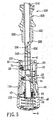
- the primary shell member 40 includes a bottom mounting wall 41 having a periphery and confronting the handle-side end of the tubular shaft 210 along the axis (L), and a primary surrounding wall 42 which includes primary left and right walls 421 (see Fig. 3 ) that are spaced apart from each other in a transverse direction relative to the axis (L), and that extend from the periphery of the bottom mounting wall 41 to terminate at primary left and right upper edges 431, respectively, so as to define a stretching path therebetween and along the axis (L).
- the primary left and right walls 421 have left and right latching slots 422, respectively, which are disposed between the primary left and right upper edges 431 and the periphery of the bottom mounting wall 41, respectively.
- the left and right latching slots 422 extend towards the periphery of the bottom mounting wall 41 so as to provide left and right leeways to be described hereinafter.
- the transmitting mechanism 60 includes a thrust transmitting member 61, a first biasing member 64, left and right latch members 62, and left and right biasing members 63.
- the thrust transmitting member 61 has a rammed end 614 to be thrusted by the tubular plunging end 223 so as to displace from a lifted position, as shown in Figs. 5 and 6 , where the tubular plunging end 223 is remote from the rammed end 614, to a depressed position, as shown in Fig.
- the rammed end 614 is engaged with the tubular plunging end 223, a depressing end 612 which is opposite to the rammed end 614 along the axis (L), and an actuating intermediate segment 611 which is interposed between the rammed end 614 and the depressing end 612, and which descends with the depressing end612 along the stretchingpath.
- the actuating intermediate segment 611 has left and right cam surfaces 613.
- the first biasingmember 64 is disposed to bias the thrust transmitting member 61 upwardly, i.e., to bias the rammed end 614 towards the lifted position.
- Each of the left and right latch members 62 has a pushed end 621 which engages and is forced by a respective one of the left and right cam surfaces 613 to be movable in the transverse direction between heavily and lightly pressed positions that are distal from and proximate to the axis (L) when the rammed end 614 is moved between the depressed position and the lifted position, and a latch end 622 which is opposite to the pushed end 621 in the transverse direction, and which is movable between an extended position, as shown in Fig. 3 , where the latch end 622 is engaged in a respective one of the left and right latching slots 422, and which corresponds to the depressed position of the rammed end 614, and a retracted position, as shown in Fig.
- the left and right biasing members 63 are disposed to respectively bias the pushed ends 621 of the left and right latch members 62 towards the lightly pressed position.
- the secondary shell member 10 is secured to and receives the runner sliding segment of the tubular shaft 210, and is fitted into the primary shell member 40.
- the secondary shell member 10 has upper and lower ends 121,122 which are opposite to each other along the axis (L).
- the primary shell member 40 is movable relative to the secondary shell member 10 along the axis (L) between a non-stretchedposition (as shown in Fig. 3 ) which corresponds to the extended position of the latch ends 622, where the bottom mounting wall 41 is close to the lower end 122, and a stretched position (as shown in Fig. 6 ), where the bottom mounting wall 41 is remote from the lower end 122.
- An abutment wall 15 is disposed securely at the lower end 122 such that the first biasing member 64 is disposed to abut against the depressing end 612 and the abutment wall 15 so as to bias the depressing end 612 towards the lifted position.
- a second biasing member 50 is disposed to bias the primary shell member 40 to move from the non-stretched position to the stretched position.
- the second biasing member 50 is disposed to surround and to be coaxial with the first biasing member 64 about the axis (L) such that the bottom mounting wall 41 of the primary shell member 40 can be moved away from the lower end 122 of the secondary shell member 10 by virtue of the biasing action of the second biasing member 50 when the rammed end 614 is moved to the lifted position.
- the secondary shell member 10 further has a mounting segment (10a) disposed proximate to the lower end 122, and a manually operated segment (10b) interposed between the upper end 121 and the mounting segment (10a).
- the mounting segment (10a) includes left and right mounting walls 127 (see Fig. 3 ) which are spaced apart from each other in the transverse direction to define a lower chamber that is communicated with the stretching path, and that accommodates the left and right latch members 62, and which confront the primary left and right walls 421 in the transverse direction, respectively.
- the left and right mounting walls 127 have left and right bores 1271 which extend therethrough respectively to be communicated with the lower chamber, and which, when the rammed end 614 is in the depressed position, are registered with the left and right latching slots 422, respectively, to permit the latch ends 622 to be placed in the extended position.
- the manually operated segment (10b) includes front and rear mounting walls 128 (see Fig. 2 ) which are diametrically spaced apart from each other relative to the axis (L) to define an upper chamber that surrounds the runner sliding segment of the tubular shaft 210, and that accommodates the tubular plunger 221 when the runner 220 is in the lowermost position.
- the rear mounting wall 128 has upper and lower mount regions (128a,128b) that are proximate to and distal from the upper end 121, respectively.
- the front mounting wall 128 has upper and lower access openings 123, 124 that permit access to the upper and lower mount regions (128a,128b) radially and respectively. In this embodiment, the upper and lower access openings 123,124 are communicated with each other.
- the upper button unit includes a retaining member 70, an upper pushing member 20, and an upper biasing member 23.
- the retaining member 70 is disposed to be movable radially between an engaging position (as shown in Fig. 2 ), where the retaining member 70 engages the retaining hole 222 in the tubular plunger 221 in the lowermost position, and a disengaging position, where the retaining member 70 retreats to the upper mount region (128a) to be disengaged from the retaining hole 222.
- the upper pushing member 20 has an upper push button 21 which is fitted into the upper access opening 123, and which is movable radially towards the upper mount region (128a), and an upper actuating end 22 which is moved with the upper push button 21 to bring the retaining member 70 into the disengaging position.
- the upper pushing member 20 is integrally formed with the retaining member 70.
- the upper biasing member 23 is disposed to bias the upper push button 21 away from the upper mount region (108a).
- the lower button unit includes a lower pushing member 30 and a lower biasing member 33.
- the lower pushing member 30 has a lower push button 31 which is fitted into the lower access opening 124, and which is adapted to actuate the actuated end 231 of the catch member 230 through the transmitting mechanism 240 in a known manner so as to release the tubular plunging end 223 from the catch member 230 when manually pushed radially towards the lower mount region (128b), and a lower actuating end 32 which is disposed opposite to the lower push button 31 in terms of the axis (L), and which is disposed to be moved with the lower push button 31.
- the lower biasing member 33 is disposed to bias the lower push button 31 away from the lower mount region (108b).
- the lower pushing member 30 is integrally formed with the upper pushing member 20 and is made of an elastomeric material such that the upper and lower push buttons 21,31 can be independently manipulated.
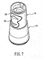
- the mounting segment (10a) of the secondary shell member 10 has a concaved keyway 125 which extends towards the lower end 122 to terminate at upper and lower limit regions.
- the primary shell member 40 has a key 43 which extends transversely to the axis (L) to be slidably engaged in the keyway 125, thereby guiding the bottom mounting wall 41 to move relative to the lower end 122 until the key 43 reaches one of the upper and lower limit regions.
- the retaining member 70 When the push-button operated extendable handle assembly of this invention is in the state shown in Figs. 2 to 4 , the retaining member 70 is in the engaging position, i.e. the retaining member 70 engages the retaining hole 222, so as to hold the rammed end 614 in the depressed position against a biasing action of the first biasing member 64, thereby placing the pushed ends 621 of the latch members 62 in the heavily pressed position.
- the primary shell member 40 is in the non-stretched position, and the lower pushing member 30 is retreated into the primary shell member 40 to prevent an undesired operation.
- the user pushes the lower push button 31 to release the runner 220 from the catch member 230 so as to permit the runner 220 to move to the lowermost position such that the tubular plunger 221 is moved into the upper chamber in the secondary shell member 10 to place the retaining member 70 in the retaining hole 222.
- the rammed end 614 is forced by the tubular plunging end 223 to the depressed position, and the latch ends 622 are moved to the retracted position, i.e. the latch ends 622 are inserted into the latching slots 422 so as to hold the primary shell member 40 in the non-stretched position.
- the leeways provided by the latching slots 422 facilitate insertion and engagement of the latch ends 622 therein.
- the primary shell member 40 when the runner 220 is in the lowermost position corresponding the closed position of the canopy of the umbrella 200, the primary shell member 40 is in the non-stretched position so that the assembly 100 has a relatively small length, thereby making the umbrella 200 more compact for carrying and storage. Moreover, the lower push button 31 can be retreated into the primary shell member 40 to prevent undesired operation thereof. When the runner 220 is in the uppermost position corresponding the opened position of the canopy of the umbrella 200, the primary shell member 40 is in the stretched position so that the assembly 100 has a relatively large length, thereby lengthening the umbrella 200 to facilitate gripping of the assembly 100.
Landscapes
- Walking Sticks, Umbrellas, And Fans (AREA)
Priority Applications (1)
| Application Number | Priority Date | Filing Date | Title |
|---|---|---|---|
| EP07012681A EP2008540A1 (fr) | 2007-06-28 | 2007-06-28 | Ensemble de poignée extensible fonctionnant avec un bouton-poussoir pour un parapluie |
Applications Claiming Priority (1)
| Application Number | Priority Date | Filing Date | Title |
|---|---|---|---|
| EP07012681A EP2008540A1 (fr) | 2007-06-28 | 2007-06-28 | Ensemble de poignée extensible fonctionnant avec un bouton-poussoir pour un parapluie |
Publications (1)
| Publication Number | Publication Date |
|---|---|
| EP2008540A1 true EP2008540A1 (fr) | 2008-12-31 |
Family
ID=39312974
Family Applications (1)
| Application Number | Title | Priority Date | Filing Date |
|---|---|---|---|
| EP07012681A Withdrawn EP2008540A1 (fr) | 2007-06-28 | 2007-06-28 | Ensemble de poignée extensible fonctionnant avec un bouton-poussoir pour un parapluie |
Country Status (1)
| Country | Link |
|---|---|
| EP (1) | EP2008540A1 (fr) |
Citations (3)
| Publication number | Priority date | Publication date | Assignee | Title |
|---|---|---|---|---|
| US5060684A (en) * | 1990-09-10 | 1991-10-29 | Wu Tsun Zong | Automatic umbrella foldably retained by tip cap |
| US20040025914A1 (en) * | 2002-08-12 | 2004-02-12 | Shih-Shin Kuo | Protecting structure for a button of an auto-umbrella |
| DE202006003362U1 (de) * | 2006-03-03 | 2006-06-08 | Kuo, Shih-Shin | Von Hand zu öffnender und selbstschließender Schirm |
-
2007
- 2007-06-28 EP EP07012681A patent/EP2008540A1/fr not_active Withdrawn
Patent Citations (3)
| Publication number | Priority date | Publication date | Assignee | Title |
|---|---|---|---|---|
| US5060684A (en) * | 1990-09-10 | 1991-10-29 | Wu Tsun Zong | Automatic umbrella foldably retained by tip cap |
| US20040025914A1 (en) * | 2002-08-12 | 2004-02-12 | Shih-Shin Kuo | Protecting structure for a button of an auto-umbrella |
| DE202006003362U1 (de) * | 2006-03-03 | 2006-06-08 | Kuo, Shih-Shin | Von Hand zu öffnender und selbstschließender Schirm |
Similar Documents
| Publication | Publication Date | Title |
|---|---|---|
| US8966771B2 (en) | Out of front knife with assisted opening mechanism | |
| US5384442A (en) | Control knob assembly for a cooking appliance | |
| US10458748B2 (en) | Holster | |
| US10080412B2 (en) | Telescopic handle for piece of luggage | |
| US6834432B1 (en) | Pocket knife with lock design | |
| US6122800A (en) | Expandable pull rod of luggage | |
| US5488756A (en) | Handle device | |
| US6148477A (en) | Expandable pull rod of luggage | |
| US5727898A (en) | Locating structure for luggage pull rod | |
| US6989503B2 (en) | Power tool trigger assembly | |
| US6812425B1 (en) | Locking trigger switch mechanism | |
| GB2553611A (en) | Adjustable kettlebell device | |
| KR100861617B1 (ko) | 회로 차단기 로크-아웃 어셈블리 | |
| US7134168B1 (en) | Door closer with pre-set stops | |
| US20080314425A1 (en) | Push-button operated extendable handle assembly for an umbrella | |
| EP2008540A1 (fr) | Ensemble de poignée extensible fonctionnant avec un bouton-poussoir pour un parapluie | |
| GB2441739A (en) | Push-button operated extendable handle assembly for an umbrella | |
| US20100132199A1 (en) | Cutting knife | |
| US5318067A (en) | Simplified fully automatic umbrella | |
| RU2343811C1 (ru) | Узел раздвижной ручки для зонта, управляемый кнопкой | |
| US20030041741A1 (en) | Separable handle for cooking vessel and cooking vessel | |
| US7168438B2 (en) | Control device for opening and closing automatic umbrella | |
| EP0518814A2 (fr) | Parapluie à ouverture et fermeture automatique | |
| KR101923684B1 (ko) | 푸쉬풀 도어락의 내부 강제잠금 해제를 위한 조립체 | |
| KR20090011692A (ko) | 푸시-버튼 작동 신장형 우산 손잡이 조립체 |
Legal Events
| Date | Code | Title | Description |
|---|---|---|---|
| PUAI | Public reference made under article 153(3) epc to a published international application that has entered the european phase |
Free format text: ORIGINAL CODE: 0009012 |
|
| 17P | Request for examination filed |
Effective date: 20070709 |
|
| AK | Designated contracting states |
Kind code of ref document: A1 Designated state(s): AT BE BG CH CY CZ DE DK EE ES FI FR GB GR HU IE IS IT LI LT LU LV MC MT NL PL PT RO SE SI SK TR |
|
| AX | Request for extension of the european patent |
Extension state: AL BA HR MK RS |
|
| STAA | Information on the status of an ep patent application or granted ep patent |
Free format text: STATUS: THE APPLICATION HAS BEEN WITHDRAWN |
|
| 18W | Application withdrawn |
Effective date: 20090120 |