EP2008548A1 - Élément coussin, siège et procédé de fabrication associé - Google Patents
Élément coussin, siège et procédé de fabrication associé Download PDFInfo
- Publication number
- EP2008548A1 EP2008548A1 EP07740266A EP07740266A EP2008548A1 EP 2008548 A1 EP2008548 A1 EP 2008548A1 EP 07740266 A EP07740266 A EP 07740266A EP 07740266 A EP07740266 A EP 07740266A EP 2008548 A1 EP2008548 A1 EP 2008548A1
- Authority
- EP
- European Patent Office
- Prior art keywords
- cushion body
- fibrous structure
- sheet
- load
- load receiving
- Prior art date
- Legal status (The legal status is an assumption and is not a legal conclusion. Google has not performed a legal analysis and makes no representation as to the accuracy of the status listed.)
- Granted
Links
Images


Classifications
-
- A—HUMAN NECESSITIES
- A47—FURNITURE; DOMESTIC ARTICLES OR APPLIANCES; COFFEE MILLS; SPICE MILLS; SUCTION CLEANERS IN GENERAL
- A47C—CHAIRS; SOFAS; BEDS
- A47C27/00—Spring, stuffed or fluid mattresses or cushions specially adapted for chairs, beds or sofas
- A47C27/12—Spring, stuffed or fluid mattresses or cushions specially adapted for chairs, beds or sofas with fibrous inlays, e.g. made of wool, of cotton
- A47C27/121—Spring, stuffed or fluid mattresses or cushions specially adapted for chairs, beds or sofas with fibrous inlays, e.g. made of wool, of cotton with different inlays
-
- A—HUMAN NECESSITIES
- A47—FURNITURE; DOMESTIC ARTICLES OR APPLIANCES; COFFEE MILLS; SPICE MILLS; SUCTION CLEANERS IN GENERAL
- A47C—CHAIRS; SOFAS; BEDS
- A47C7/00—Parts, details, or accessories of chairs or stools
- A47C7/02—Seat parts
- A47C7/029—Seat parts of non-adjustable shape adapted to a user contour or ergonomic seating positions
-
- B—PERFORMING OPERATIONS; TRANSPORTING
- B60—VEHICLES IN GENERAL
- B60N—SEATS SPECIALLY ADAPTED FOR VEHICLES; VEHICLE PASSENGER ACCOMMODATION NOT OTHERWISE PROVIDED FOR
- B60N2/00—Seats specially adapted for vehicles; Arrangement or mounting of seats in vehicles
- B60N2/68—Seat frames
-
- B—PERFORMING OPERATIONS; TRANSPORTING
- B60—VEHICLES IN GENERAL
- B60N—SEATS SPECIALLY ADAPTED FOR VEHICLES; VEHICLE PASSENGER ACCOMMODATION NOT OTHERWISE PROVIDED FOR
- B60N2/00—Seats specially adapted for vehicles; Arrangement or mounting of seats in vehicles
- B60N2/70—Upholstery springs ; Upholstery
- B60N2/7017—Upholstery springs ; Upholstery characterised by the manufacturing process; manufacturing upholstery or upholstery springs not otherwise provided for
-
- B—PERFORMING OPERATIONS; TRANSPORTING
- B68—SADDLERY; UPHOLSTERY
- B68G—METHODS, EQUIPMENT, OR MACHINES FOR USE IN UPHOLSTERING; UPHOLSTERY NOT OTHERWISE PROVIDED FOR
- B68G7/00—Making upholstery
- B68G7/02—Making upholstery from waddings, fleeces, mats, or the like
-
- D—TEXTILES; PAPER
- D04—BRAIDING; LACE-MAKING; KNITTING; TRIMMINGS; NON-WOVEN FABRICS
- D04H—MAKING TEXTILE FABRICS, e.g. FROM FIBRES OR FILAMENTARY MATERIAL; FABRICS MADE BY SUCH PROCESSES OR APPARATUS, e.g. FELTS, NON-WOVEN FABRICS; COTTON-WOOL; WADDING ; NON-WOVEN FABRICS FROM STAPLE FIBRES, FILAMENTS OR YARNS, BONDED WITH AT LEAST ONE WEB-LIKE MATERIAL DURING THEIR CONSOLIDATION
- D04H1/00—Non-woven fabrics formed wholly or mainly of staple fibres or like relatively short fibres
- D04H1/02—Cotton wool; Wadding
-
- D—TEXTILES; PAPER
- D04—BRAIDING; LACE-MAKING; KNITTING; TRIMMINGS; NON-WOVEN FABRICS
- D04H—MAKING TEXTILE FABRICS, e.g. FROM FIBRES OR FILAMENTARY MATERIAL; FABRICS MADE BY SUCH PROCESSES OR APPARATUS, e.g. FELTS, NON-WOVEN FABRICS; COTTON-WOOL; WADDING ; NON-WOVEN FABRICS FROM STAPLE FIBRES, FILAMENTS OR YARNS, BONDED WITH AT LEAST ONE WEB-LIKE MATERIAL DURING THEIR CONSOLIDATION
- D04H1/00—Non-woven fabrics formed wholly or mainly of staple fibres or like relatively short fibres
- D04H1/40—Non-woven fabrics formed wholly or mainly of staple fibres or like relatively short fibres from fleeces or layers composed of fibres without existing or potential cohesive properties
- D04H1/44—Non-woven fabrics formed wholly or mainly of staple fibres or like relatively short fibres from fleeces or layers composed of fibres without existing or potential cohesive properties the fleeces or layers being consolidated by mechanical means, e.g. by rolling
- D04H1/50—Non-woven fabrics formed wholly or mainly of staple fibres or like relatively short fibres from fleeces or layers composed of fibres without existing or potential cohesive properties the fleeces or layers being consolidated by mechanical means, e.g. by rolling by treatment to produce shrinking, swelling, crimping or curling of fibres
-
- D—TEXTILES; PAPER
- D04—BRAIDING; LACE-MAKING; KNITTING; TRIMMINGS; NON-WOVEN FABRICS
- D04H—MAKING TEXTILE FABRICS, e.g. FROM FIBRES OR FILAMENTARY MATERIAL; FABRICS MADE BY SUCH PROCESSES OR APPARATUS, e.g. FELTS, NON-WOVEN FABRICS; COTTON-WOOL; WADDING ; NON-WOVEN FABRICS FROM STAPLE FIBRES, FILAMENTS OR YARNS, BONDED WITH AT LEAST ONE WEB-LIKE MATERIAL DURING THEIR CONSOLIDATION
- D04H1/00—Non-woven fabrics formed wholly or mainly of staple fibres or like relatively short fibres
- D04H1/40—Non-woven fabrics formed wholly or mainly of staple fibres or like relatively short fibres from fleeces or layers composed of fibres without existing or potential cohesive properties
- D04H1/54—Non-woven fabrics formed wholly or mainly of staple fibres or like relatively short fibres from fleeces or layers composed of fibres without existing or potential cohesive properties by welding together the fibres, e.g. by partially melting or dissolving
- D04H1/558—Non-woven fabrics formed wholly or mainly of staple fibres or like relatively short fibres from fleeces or layers composed of fibres without existing or potential cohesive properties by welding together the fibres, e.g. by partially melting or dissolving in combination with mechanical or physical treatments other than embossing
-
- D—TEXTILES; PAPER
- D04—BRAIDING; LACE-MAKING; KNITTING; TRIMMINGS; NON-WOVEN FABRICS
- D04H—MAKING TEXTILE FABRICS, e.g. FROM FIBRES OR FILAMENTARY MATERIAL; FABRICS MADE BY SUCH PROCESSES OR APPARATUS, e.g. FELTS, NON-WOVEN FABRICS; COTTON-WOOL; WADDING ; NON-WOVEN FABRICS FROM STAPLE FIBRES, FILAMENTS OR YARNS, BONDED WITH AT LEAST ONE WEB-LIKE MATERIAL DURING THEIR CONSOLIDATION
- D04H1/00—Non-woven fabrics formed wholly or mainly of staple fibres or like relatively short fibres
- D04H1/40—Non-woven fabrics formed wholly or mainly of staple fibres or like relatively short fibres from fleeces or layers composed of fibres without existing or potential cohesive properties
- D04H1/58—Non-woven fabrics formed wholly or mainly of staple fibres or like relatively short fibres from fleeces or layers composed of fibres without existing or potential cohesive properties by applying, incorporating or activating chemical or thermoplastic bonding agents, e.g. adhesives
- D04H1/593—Non-woven fabrics formed wholly or mainly of staple fibres or like relatively short fibres from fleeces or layers composed of fibres without existing or potential cohesive properties by applying, incorporating or activating chemical or thermoplastic bonding agents, e.g. adhesives to layered webs
-
- D—TEXTILES; PAPER
- D04—BRAIDING; LACE-MAKING; KNITTING; TRIMMINGS; NON-WOVEN FABRICS
- D04H—MAKING TEXTILE FABRICS, e.g. FROM FIBRES OR FILAMENTARY MATERIAL; FABRICS MADE BY SUCH PROCESSES OR APPARATUS, e.g. FELTS, NON-WOVEN FABRICS; COTTON-WOOL; WADDING ; NON-WOVEN FABRICS FROM STAPLE FIBRES, FILAMENTS OR YARNS, BONDED WITH AT LEAST ONE WEB-LIKE MATERIAL DURING THEIR CONSOLIDATION
- D04H1/00—Non-woven fabrics formed wholly or mainly of staple fibres or like relatively short fibres
- D04H1/40—Non-woven fabrics formed wholly or mainly of staple fibres or like relatively short fibres from fleeces or layers composed of fibres without existing or potential cohesive properties
- D04H1/58—Non-woven fabrics formed wholly or mainly of staple fibres or like relatively short fibres from fleeces or layers composed of fibres without existing or potential cohesive properties by applying, incorporating or activating chemical or thermoplastic bonding agents, e.g. adhesives
- D04H1/60—Non-woven fabrics formed wholly or mainly of staple fibres or like relatively short fibres from fleeces or layers composed of fibres without existing or potential cohesive properties by applying, incorporating or activating chemical or thermoplastic bonding agents, e.g. adhesives the bonding agent being applied in dry state, e.g. thermo-activatable agents in solid or molten state, and heat being applied subsequently
-
- D—TEXTILES; PAPER
- D04—BRAIDING; LACE-MAKING; KNITTING; TRIMMINGS; NON-WOVEN FABRICS
- D04H—MAKING TEXTILE FABRICS, e.g. FROM FIBRES OR FILAMENTARY MATERIAL; FABRICS MADE BY SUCH PROCESSES OR APPARATUS, e.g. FELTS, NON-WOVEN FABRICS; COTTON-WOOL; WADDING ; NON-WOVEN FABRICS FROM STAPLE FIBRES, FILAMENTS OR YARNS, BONDED WITH AT LEAST ONE WEB-LIKE MATERIAL DURING THEIR CONSOLIDATION
- D04H1/00—Non-woven fabrics formed wholly or mainly of staple fibres or like relatively short fibres
- D04H1/40—Non-woven fabrics formed wholly or mainly of staple fibres or like relatively short fibres from fleeces or layers composed of fibres without existing or potential cohesive properties
- D04H1/58—Non-woven fabrics formed wholly or mainly of staple fibres or like relatively short fibres from fleeces or layers composed of fibres without existing or potential cohesive properties by applying, incorporating or activating chemical or thermoplastic bonding agents, e.g. adhesives
- D04H1/64—Non-woven fabrics formed wholly or mainly of staple fibres or like relatively short fibres from fleeces or layers composed of fibres without existing or potential cohesive properties by applying, incorporating or activating chemical or thermoplastic bonding agents, e.g. adhesives the bonding agent being applied in wet state, e.g. chemical agents in dispersions or solutions
-
- D—TEXTILES; PAPER
- D04—BRAIDING; LACE-MAKING; KNITTING; TRIMMINGS; NON-WOVEN FABRICS
- D04H—MAKING TEXTILE FABRICS, e.g. FROM FIBRES OR FILAMENTARY MATERIAL; FABRICS MADE BY SUCH PROCESSES OR APPARATUS, e.g. FELTS, NON-WOVEN FABRICS; COTTON-WOOL; WADDING ; NON-WOVEN FABRICS FROM STAPLE FIBRES, FILAMENTS OR YARNS, BONDED WITH AT LEAST ONE WEB-LIKE MATERIAL DURING THEIR CONSOLIDATION
- D04H1/00—Non-woven fabrics formed wholly or mainly of staple fibres or like relatively short fibres
- D04H1/70—Non-woven fabrics formed wholly or mainly of staple fibres or like relatively short fibres characterised by the method of forming fleeces or layers, e.g. reorientation of fibres
- D04H1/74—Non-woven fabrics formed wholly or mainly of staple fibres or like relatively short fibres characterised by the method of forming fleeces or layers, e.g. reorientation of fibres the fibres being orientated, e.g. in parallel (anisotropic fleeces)
-
- Y—GENERAL TAGGING OF NEW TECHNOLOGICAL DEVELOPMENTS; GENERAL TAGGING OF CROSS-SECTIONAL TECHNOLOGIES SPANNING OVER SEVERAL SECTIONS OF THE IPC; TECHNICAL SUBJECTS COVERED BY FORMER USPC CROSS-REFERENCE ART COLLECTIONS [XRACs] AND DIGESTS
- Y10—TECHNICAL SUBJECTS COVERED BY FORMER USPC
- Y10S—TECHNICAL SUBJECTS COVERED BY FORMER USPC CROSS-REFERENCE ART COLLECTIONS [XRACs] AND DIGESTS
- Y10S5/00—Beds
- Y10S5/948—Body support with unique, specific filler material
- Y10S5/952—Comprising artificial fiber
-
- Y—GENERAL TAGGING OF NEW TECHNOLOGICAL DEVELOPMENTS; GENERAL TAGGING OF CROSS-SECTIONAL TECHNOLOGIES SPANNING OVER SEVERAL SECTIONS OF THE IPC; TECHNICAL SUBJECTS COVERED BY FORMER USPC CROSS-REFERENCE ART COLLECTIONS [XRACs] AND DIGESTS
- Y10—TECHNICAL SUBJECTS COVERED BY FORMER USPC
- Y10T—TECHNICAL SUBJECTS COVERED BY FORMER US CLASSIFICATION
- Y10T156/00—Adhesive bonding and miscellaneous chemical manufacture
- Y10T156/10—Methods of surface bonding and/or assembly therefor
-
- Y—GENERAL TAGGING OF NEW TECHNOLOGICAL DEVELOPMENTS; GENERAL TAGGING OF CROSS-SECTIONAL TECHNOLOGIES SPANNING OVER SEVERAL SECTIONS OF THE IPC; TECHNICAL SUBJECTS COVERED BY FORMER USPC CROSS-REFERENCE ART COLLECTIONS [XRACs] AND DIGESTS
- Y10—TECHNICAL SUBJECTS COVERED BY FORMER USPC
- Y10T—TECHNICAL SUBJECTS COVERED BY FORMER US CLASSIFICATION
- Y10T29/00—Metal working
- Y10T29/49—Method of mechanical manufacture
- Y10T29/49826—Assembling or joining
Definitions
- the present invention relates to a cushion body, a seat, and a method of manufacturing the same, and in particular to a cushion body and a seat using a fibrous structure composed of polyester fibers or the like, and a method of manufacturing the same.
- a seat using a fibrous structure composed of polyester fibers or the like as a cushion body has been known (for example, see Patent Document 1).
- the fibrous structure used in the seat described in Patent Document 1 is formed by successively folding a web obtained by dispersing and incorporating thermally adhesive composite short fibers as adhesive component into matrix fibers composed of an inelastic polyester crimped short fiber assembly in a standing state along its longitudinal direction. That is, this fibrous structure is formed to have a predetermined thickness by folding the web in an accordion shape.
- each of a seat portion and a seat back portion is constituted by stacking a plurality of this fibrous structures to form a cushion body and coating this cushion body with a cover. Accordingly, in this seat, since the standing direction of the web (a thickness direction of the cushion body) is directed along a load direction during sitting of a seat occupant, excellent ventilation is, of course, secured, a proper hardness to a load direction is provided, and load can be dispersed. Therefore, this seat can provide soft touch feeling which cannot be obtained by urethane conventionally used in general.
- Patent Document 1 Japanese Patent Laid Open Publication No. 1996(H08)-318066
- the seat described in Patent Document 1 Since the seat described in Patent Document 1 has a structure that a longitudinal direction of fibers extends along a load direction, it can support a sufficient load while maintaining soft touch feeling.
- the seat described in Patent Document 1 since each of the seat portion and the seat back portion is formed by only stacking a plurality of accordion-shaped fibrous structures, soft touch feeling can be obtained but there is a problem that durability is poor as a seat.
- the number of stacks of fibrous structures is increased in order to improve the durability, hardness can be obtained to some extent, but such a drawback arises that unique soft touch feeling of the fibrous structures is lost from the fibrous structures.
- An object of the present invention is to provide a cushion body and a seat which can secure both soft touch feeling and durability by stacking a plurality of fibrous structures with a predetermined thickness folded in a standing state, a method of manufacturing the same.
- a cushion body of the present invention is a cushion body obtained by molding a fibrous structure obtained by mixing main fibers and binder fibers using a mold having a cavity with a predetermined shape, wherein the cushion body is formed by stacking a plurality of the fibrous structures, a load receiving member whose flexing degree to load in a thickness direction is smaller than that of the fibrous structure is disposed between the plurality of fibrous structures stacked.
- the cushion body of the present invention is formed by the fibrous structure in which the main fibers and the binder fibers are mixed, the cushion body flexes largely in a load direction when it is applied with external load due to sitting or the like. Therefore, soft touch feeling can be provided to a seat occupant during seating. Since the load receiving member whose flexing degree to load in the thickness direction is smaller than the fibrous structure is disposed between the plurality of fibrous structures, when the fibrous structure receives load in the thickness direction, the load receiving member can receive and disperse the load from the fibrous structure. Accordingly, fatigue in the load direction hardly occurs in the cushion body so that durability of the cushion body can be secured. Thus, according to the cushion body of the present invention, both soft touch feeling and durability can be realized.
- the load receiving member is formed from a fiber material or a resin material.
- the load receiving member is preferably formed from approximately the same fiber material as the fibrous structure and is formed to have a fiber density higher than that of the fibrous structure.
- the fibrous structure and the load receiving member are formed from approximately the same fiber material and they are made different in fiber density, so that both the structures can be constituted to have different flexing degrees. Since the fibrous structure and the load receiving member are formed from approximately the same fiber material, it is unnecessary to separate the fibrous structures into respective different fiber materials at disposal of the cushion body so that work for separation is omitted, which results in improvement of recycling easiness.
- the seat of the present invention is a seat including a cushion body and a seat frame supporting the cushion body, wherein the cushion body is any one of the cushion bodies described above.
- the seat of the present invention uses the cushion body provided with soft touch feeling and durability such as described above, it is provided with soft touch feeling during sitting on the seat and high durability to load due to sitting on the seat.
- the method of manufacturing a cushion body according to the present invention is a method of manufacturing a cushion body comprising a fibrous structure, comprising at least: a fibrous structure forming step of successively folding a web composed of main fibers and binder fibers for each predetermined length to form a fibrous structure as a stacked state; a fibrous structure disposing step of stacking a plurality of the fibrous structures and disposing the fibrous structure and the load receiving member in a mold having a cavity with a predetermined shape in a stacked and compressed state, where the load receiving member whose flexing degree to load in the thickness direction is smaller than that of the fibrous structure is disposed between the plurality of fibrous structures stacked; and a molding step of thermally molding the fibrous structure and the load receiving member in the mold to form a cushion body.
- the plurality of fibrous structures and the load receiving member are disposed in a state that they are stacked and compressed in the mold and be thermally molded, integral molding can be preformed in the mold. Therefore, a bonding step can be skipped unlike a case that the fibrous structure and load receiving member as well as the fibrous structures are bonded to each other using adhesive, so that tact time spent for cushion body manufacture can be reduced.
- the fibrous structures are disposed in the molding formed with steam holes in a compressed state thereof, and steam is blown to the fibrous structure under barometrical pressure higher than atmospheric pressure.
- steam blown to the mold can pass through the inside of the fibrous structures through the steam holes formed in the mold without causing adiabatic expansion while it is being kept at a molding temperature.
- steam has heat capacity larger than hot air
- the fibrous structure can be molded in a short time so that a molding time can be reduced largely in the present invention. Since the molding time is reduced, heating process time of the fibrous structure is reduced, so that texture of the cushion body after molded can be made good.
- the steam holes are formed to be more in a region corresponding to the side of a non-load receiving face which does not receive load from outside the cushion body than in a region corresponding to the load receiving face which receives the load from outside the cushion body in the mold, and steam is blown to the fibrous structure through the steam holes on the side of the non-load receiving face in the molding step.
- the number of the fibrous structures disposed between the load receiving face which receives the load from outside the cushion body and the load receiving member is adjusted in stacking according to touch feeling required for the cushion body after thermal molding.
- the touch feeling from the load receiving member received by the seat occupant when sitting can be made different according to the number of, that is, thickness of the fibrous structures between the load receiving face and the load receiving member. Accordingly, a cushion body provided with a desired touch feeling can be manufactured.
- a method of manufacturing a seat according to the present invention is a method of manufacturing a seat comprising a cushion body and a seat frame supporting the cushion body, comprising at least: a step of forming the cushion body according to the manufacturing method of the cushion body described above; and a step of attaching the cushion body to the seat frame.
- the method of manufacturing a seat according to the present invention can provide a seat having both soft touch feeling during sitting on the seat and durability to load applied during sitting on the seat.
- the cushion body is formed by the fibrous structure in which the main fibers and the binder fibers are mixed, the cushion body flexes largely in a load direction when it is applied with external load, and soft touch feeling can be provided. Also, since the load receiving member has a flexing degree to load in the thickness direction smaller than that of the fibrous structure and maintains harness to some extent, durability can be improved by dispersing the load received by the fibrous structure. Thus, according to the cushion body of the present invention, both soft touch feeling and durability can be realized.
- Fig. 1 to Fig. 8 show an embodiment of the present invention
- Fig. 1 being an explanatory diagram of a seat
- Fig. 2 being an explanatory diagram of a fiber direction in a web
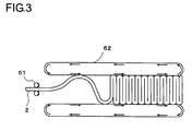
- Fig. 3 being an explanatory diagram of a manufacturing step of a sheet-like fibrous structure
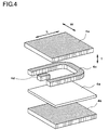
- Fig. 4 being an explanatory diagram of the sheet-like fibrous structure before stacked
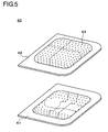
- Fig. 5 being an explanatory diagram of a mold
- Fig. 6 and Fig. 7 being explanatory diagrams of a manufacturing step of a cushion body
- Fig. 8 being a sectional explanatory diagram of the cushion body.
- a seat 1 of the embodiment can be applied to a seat for a vehicle, a train, an airplane or the like, and it may be also applied to various chairs such as a business chair or a care chair.
- the seat 1 of this embodiment is provided with a seat portion 10 and a seat back portion 20, as shown in Fig. 1 .
- the seat portion 10 and the seat back portion 20 are respectively constituted such that cushion bodies 11 and 21 are placed on seat frames 15 and 25 and the cushion bodies 11 and 21 are coated with covers 13 and 23.
- the cushion body 11 in this embodiment is formed by forming a sheet-like fibrous structure as a fibrous structure where a web 2 has been folded in a standing state (a fibrous structure forming step) described later, cutting this sheet-like fibrous structure into fibrous structure pieces with predetermined shapes to stack a plurality of cut fibrous structure pieces and disposing the plurality of cut fibrous structure pieces in a mold 40 formed with a plurality of steam holes 43 which are air holes on its mold face (a fibrous structure disposing step), and performing high pressure steam molding in high pressure steam molding machine 50 in a state the mold 40 has been clamped (a molding step).
- the web 2 for forming the cushion body 11 of this embodiment will be explained with reference to Fig. 2 and Fig. 3 .
- the web 2 is one obtained by dispersing and mixing, in matrix fibers composed of assemblies of inelastic crimped short fibers, thermally adhesive composite short fibers having a melting point lower than that of the inelastic crimped short fibers and having a melting point of at least 120°C as adhesive component.
- the web 2 in this embodiment is one obtained by performing cotton blending of inelastic polyester crimped short fibers as the inelastic crimped short fibers and the thermally adhesive composite short fibers composed of thermoplastic elastomer having a melting point lower than a melting point of polyester polymer constituting the inelastic polyester crimped short fibers by 40°C and inelastic polyester such that the fibers are mainly directed in a longitudinal direction of the web 2.
- the web 2 of this embodiment has a bulk property of at least 30 kg/m 3 and it is formed with cubic fiber crossing points between the thermally adhesive composite short fibers and between the thermally adhesive composite short fibers and the inelastic polyester crimped short fibers.
- hollow polyethylene terephthalate fiber with a single yarn fineness of 12 deniers and a fiber length of 64mm which have cubic crimp due to anisotropic cooling are used as the inelastic polyester crimped short fibers.
- the inelastic polyester crimped short fibers short fibers made from ordinary polyethylene terephthalate, polytrimethylene terephthalate, polybutylene terephthalate, polyhexamethylene terephthalate, polytetramethylene terephthalate, poly-1, 4-dimethylcyclohexane terephthalate, polypivalolactone, or copolymer ester thereof, cotton blended material of these fibers, composite fibers composed of two or more kinds of the above polymer components, or the like can be used.
- Short fibers of polyethylene terephtalate, polytrimethylene terephthalate, or polybutylene terephthalate of these short fibers are desirable. Further, potential crimped fibers composed of two kinds of polyethylene terephthalate and polytrimethylene terephthalate whose inherent viscosities are different from each other or a combination thereof, where crimps have micro-crimps due to heat treatment or the like can also be used.
- a sectional shape of the short fiber may be circular, oval, hyterotypic, or hollow.
- a thickness of this short fiber is in a range of 2 to 200 deniers, especially, preferably in a range of 6 to 100 deniers. Incidentally, when the thickness of the short fiber is small, softness increases, but elasticity of the cushion body often lowers.
- the thickness of the short fiber is excessively thick, handling easiness, especially, formability of the web 2 deteriorates. Furthermore, there is a possibility that the number of constituent fibers decreases excessively, the number of crossing points formed between the short fibers and the thermally adhesive composite short fibers also decreases so that elasticity of the cushion body is hard to develop and simultaneously durability lowers. Furthermore, texture becomes excessively rough and hard.
- the thermally adhesive composite short fibers are composed of thermoplastic elastomer and inelastic polyester. Then, it is preferable that the former occupies at least 1/2 of a fiber surface. Regarding a weight ratio, it is appropriate that the former and the latter are in a range of 30/70 to 70/30 in a composite ratio.
- the thermally adhesive composite short fibers may be of a side by side type or of a sheath-core type, but the latter is desirable.
- the inelastic polyester constitutes the core, but the core may be concentric or eccentric. Especially, the eccentric type is more desirable because coil-like elastic crimps are developed.
- thermoplastic elastomer polyurethane elastomer or polyester elastomer is desirable. Especially, the latter is appropriate.
- polyurethane elastomer polyol with a low melting point having a molar weight of about 500 to 6000, for example, dihydroxy polyether, dihydroxy polyester, dihydroxy polycarbonate, dihydroxy polyester amide, or the like, organic diisocyanate with a molar weight of 500 or less, for example, p, p-diphenylmethane diisocyanate, tolylene diisocyanate, isophorone diisocyanate, diphenylmethane diisocyanate hydride, xylylene diisocyanate, 2, 6-diisocyanate methyl caproate, hexamethylene diisocyanate, or the like, chain extender with a molar weight of 500 or less, for example, polymer obtained by reaction with glycol, amino alcohol, or triol are used.
- polytetramethylene glycol as polyol, or polyurethane using poly- ⁇ -caprolactone or polybutylene adipate.
- p, p'-diphenylmethane diisocynate is desirable as organic diisocyanate.
- p, p'-bidihydroxy-ethoxy benzene and 1, 4- butane diol are desirable as the chain extender.
- polyester elastomer polyether ester block copolymer obtained by performing copolymerization using thermoplastic polyester as hard segment and using poly (alkylene oxide) glycol as soft segment
- temary copolymer composed of at least one of dicarboxylic acids selected from aromatic dicarboxylic acid such as terephthalic acid, isophthalic acid, phthalic acid, naphthalene-2, 6-dicarboxylic acid, naphtalene-2, 7-dicarboxylic acid, diphenyl-4, 4'-dicarboxylic acid, diphenoxy-ethane dicarboxylic acid, or 3-sodium sulfoisophthalic acid, alicyclic dicarboxylic acid such as 1, 4-cyclohexane dicarboxylic acid, aliphatic dicarboxylic acid such as succinate, oxalic acid, adipic acid, sebacic acid dodecanedioic acid, dimer acid, esteramide
- the polyester component constituting the hard segment includes terephthalic acid as main acid component, and polybutylene terephthalate which is butylene glycol component as main diol component.
- terephthalic acid as main acid component
- polybutylene terephthalate which is butylene glycol component as main diol component.
- a portion (generally, 30 mol% or less) of this acid component may be replaced with other dicarboxylic acid component or oxycarboxylic acid component, and similarly a portion (generally, 30 mol% or less) of glycol component may be replaced with dioxy component other than butylene glycol component.
- polyether portion constituting the soft segment may be polyether replaced with dioxy component other than butylene glycol.
- various stabilizers, ultraviolet absorbent, thickening branching agent, delusterant, colorant, or other various improvers or the like may be blended in polymer according to necessity.
- the degree of polymerization of polyester elastomer is in a range of 0.8 to 1.7 dl/g, especially, in a range of 0.9 to 1.5 dl/g regarding inherent viscosity. If this inherent viscosity is excessively low, a heat adhesion spot formed by the inelastic polyester crimped short fibers constituting the matrix is made breakable. On the other hand, if the inherent viscosity is excessively high, a spindle-shaped node becomes hard to be formed at a heat adhesion time.
- a fracture elongation is preferably 500% or more, more preferably, 800% or more. If this elongation is excessively low, when the cushion body 11 is compressed and the deformation reaches the heat adhesion point, coupling at this portion becomes breakable.
- an elongation stress of 300% of the thermoplastic elastomer is preferably 0.8 kg/mm 2 or less, more preferably, 0.8 kg/mm 2 . If this stress is excessively large, it becomes hard for the heat-adhesion spot to disperse force applied on the cushion body 11, so that, when the cushion body 11 is compressed, the heat-adhesion spot may be broken by the force applied at that time, or even if it is not broken, the inelastic polyester crimped short fibers constituting the matrix may be also strained or crimps may fatigue.
- thermoplastic elastomer is preferably 60% or more, more preferably, 70% or more.
- this elongation recovery ratio is low, even if the cushion body 11 is compressed so that the heat-adhesion spot is deformed, recovery to its original state may become hard.
- these thermoplastic elastomers have melting points lower than polymer constituting the inelastic polyester crimped short fibers and they do not cause crimps of the crimped short fibers to thermally fatigue at a hot-melting processing time for forming the heat-adhesion spot. Therefore, the melting point is preferably lower than the melting point of the polymer constituting the short fibers by 40°C or more, more preferably, by 60°C or more.
- Such a melting point of the thermoplastic elastomer can be set to a temperature in a range of 120 to 220°C, for example.
- thermoplastic elastomer when its melting point can not be observed clearly, a softening point thereof is observed instead of the melting point.
- polyester polymers constituting the crimped short fibers forming the matrix such as described above, are adopted, but polyethylene terephthalate, polymethylene terephthalate, or polybutylene terephthalate is more preferably adopted among them.
- the above-described composite fibers are dispersed and blended in a range of 20 to 100%, preferably, 30 to 80% based upon weight of the web 2.
- the thermally adhesive composite short fibers as the binder fibers and the inelastic crimped short fibers as the main fibers are cotton-blended at a weight ratio of 60: 40.
- the inelastic polyester crimped short fibers and the thermally adhesive composite short fibers are cotton-blended at the weight ratio of 40: 60, and they are formed in the web 2 of coating weight 20 g/m 2 through a roller card.
- the web 2 in this embodiment is formed such that a ratio of fibers oriented in the lengthwise direction of the web is relatively higher than that of fibers oriented in a lateral direction. That is, the web 2 in this embodiment is formed so as to satisfy a relationship of C ⁇ 3D/2, preferably, C ⁇ 2D per unit volume.
- C: D 2: 1.
- the fibers oriented in the lengthwise direction of the web 2 are fibers satisfying such a condition that an angle ⁇ of the lengthwise direction of the fibers to the lengthwise direction of the web is in a range of 0° ⁇ 45°, while the fibers oriented in the lateral direction (the widthwise direction of the web) are fibers satisfying such a condition that the angle ⁇ is in a range of 45° ⁇ 90°.
- reference symbol a represents fibers constituting the web
- reference symbol b represents the lengthwise direction (extending direction) of the web
- reference symbol c represents the fiber direction constituting the web.
- a thickness direction of the sheet-like fibrous structure and a direction extending along a direction perpendicular to a thickness direction thereof means directions within a range of ⁇ 45° to these directions.
- a direction where each fiber directs can be observed by extracting random portions in a surface layer portion andean inner layer portion of the web 2 to observe them using a transmission type optical microscope.
- the thickness of the web 2 is 5mm or more, preferably, 10mm or more, further preferably 20 mm or more.
- the web 2 has a thickness of 5 to 150 mm.
- the web 2 formed such that fibers mainly extend along the lengthwise direction is folded like an accordion such that it has a predetermined density and a desired thickness as a structural body, so that cubic fiber crossing points are formed between the composite fibers and between the inelastic polyester crimped short fiber and the composite fibers, and heat treatment is then performed at a temperature (to 80°C) lower than the melting point of the polyester polymer and higher than the melting point (or a fluidization start point) of the thermoplastic elastomer, so that elastomer component are melt-adhered at the fiber crossing points and flexible heat-adhesion spots are formed.
- the web 2 is folded to an accordion shape by pushing the web 2 into a hot-air suction type heat treatment machine 62 (a length of a heat treatment zone is 5 m and a moving velocity is 1m/min) by a driving roller 61 with a roller surface velocity of 2.5 m/min and it is formed in a heat-adhered sheet-like fibrous structure with a thickness of 25mm by treating the web 2 at 190°C for 5 minutes using Struto equipment (a fibrous structure forming step).
- a hot-air suction type heat treatment machine 62 a length of a heat treatment zone is 5 m and a moving velocity is 1m/min
- a driving roller 61 with a roller surface velocity of 2.5 m/min and it is formed in a heat-adhered sheet-like fibrous structure with a thickness of 25mm by treating the web 2 at 190°C for 5 minutes using Struto equipment (a fibrous structure forming step).
- Adhesion spots thermally adhering in a state the thermally adhesive composite short fibers have crossed one another and adhesion spots thermally adhering in a state that the thermally adhesive composite short fibers and the inelastic crimped short fibers have crossed one another are dispersed in the sheet-like fibrous structure thus formed. It is appropriate for developing cushioning properties, ventilation properties, and elasticity that the density of the sheet-like fibrous structure is in a range of 5 to 200 kg/m 3 .
- the sheet-like fibrous structure is formed such that the number of fibers oriented in the thickness direction is larger than that of fibers oriented in a direction perpendicular to this thickness direction and a direction of the fibers mainly becomes parallel to the thickness direction. That is, the sheet-like fibrous structure in the embodiment is formed such that when the total number of fibers arranged along in the thickness direction is represented as A and the number of fibers arranged along the direction perpendicular to the thickness direction is represented as B regarding per unit volume, a relationship of A ⁇ 3B/2, preferably, A ⁇ 2B is satisfied.
- the sheet-like fibrous structure is cut in a predetermined shape, and cut pieces are stacked in a vertical direction (a thickness direction T), as shown in Fig. 4 .
- a widthwise direction of the cushion body 11 a lengthwise
- the first sheet-like fibrous structure 4a and the second sheet-like fibrous structure 4b having equivalent fiber material and fiber density to those of the first sheet-like fibrous structure 4a are stacked. It is preferable that the fiber density of the first sheet-like fibrous structure 4a and the second sheet-like fibrous structure 4b is in a range of 10 to 35 kg/m 3 before thermal molding. Incidentally, the first sheet-like fibrous structure 4a and the second sheet-like fibrous structure 4b correspond to the fibrous structure of the present invention.
- the first sheet-like fibrous structure 4a is formed of a sheet-like fibrous structure obtained by folding the web 2 obtained by blending the main fibers and the binder fibers in a standing state.
- the first sheet-like fibrous structure 4a is arranged on a side (an upper side on Fig. 4 ) of a sitting surface 10a of the seat 1, and it serves to receive load from a body of a seat occupant directly or indirectly via a cover.
- the second sheet-like fibrous structure 4b is formed of a sheet-like fibrous structure made from substantially the same fiber material as that of the first sheet-like fibrous structure 4a.
- the second sheet-like fibrous structure 4b is arranged on the side (a lower side on Fig. 4 ) of the seat frame 15 of the seat 1.
- the load receiving member 4e is a flat-plate state member and serves to support load to the thickness direction T generated by sitting of a seat occupant on the sitting surface 10a and dispersing it.
- the load receiving member 4e is formed by a material whose flexing degree to load in the thickness direction T is smaller than that of the first sheet-like fibrous structure 4a and the second sheet-like fibrous structure 4b.
- resins such as polyester elastomer may be cited.
- fibers durable to the thickness direction may be used as a form of the load receiving member 4e.
- potential crimped fibers fiber sheets obtained by machining a felt-like fiber manufactured by Struto equipment in a plate state, or a resin molded product obtained by molding the resin in a plate state may be used.
- the U-shaped sheet-like fibrous structure 4c is a fibrous structure for forming a bank portion of the cushion body 11, which will be described later
- the protrusion-shaped sheet-like fibrous structure 4d is a fibrous structure for forming a protrusion portion of the cushion body 11.
- sheet-like fibrous structures 4a to 4d and the load receiving member 4e are stacked in their thickness direction T. That is, stacking is performed such that a direction of fibers extends in a vertical direction. Further, holt-melt films, hot-melt unwoven cloths, hot-melt adhesives, or the like are arranged at portions where the sheet-like fibrous structures 4a to 4d abut on one another and portions where the sheet-like fibrous structures 4a to 4d and the load receiving member 4c abut on one another according to necessity.
- the sheet-like fibrous structures 4a to 4d and the load receiving member 4e thus stacked are arranged in a mold 40 such as shown in Fig. 5 and compressed (a fibrous structure arranging step).
- the mold 40 of this embodiment is composed of a first mold 41 and a second mold 42.
- the first mold 41 is a mold used to form a shape of the cushion body 11 positioned on the side of the sitting surface 10a (namely, a surface)
- the second mold 42 is a mold used to form a shape of the cushion body 11 positioned on the side of the seat frame 15, namely, on the side of a back surface 10b (a non-load receiving face).
- a cavity 40a having a desired undulation shape of the cushion body 11 is formed.
- steam holes 43 are formed on a portion or a whole of a mold face of the mold 40.
- the steam holes are hardly formed on the first mold 41 while a plurality of steam holes 43 are bored over a whole face of the second mold 42 in the second mold 42.
- the mold 40 can be formed using such metal as iron, steel, aluminum, glass fiber, or carbon fiber, or it may be formed of any synthetic resin.
- Fig. 6 is a sectional view of a state that the sheet-like fibrous structures 4a to 4d and the load receiving member 4e have been disposed in the mold 40 and the mold 40 has been fastened.
- the sheet-like fibrous structures 4a to 4d are formed to be larger than the cavity 40a of the mold 40 in a natural state by about 1.2 to 3.0 times in volume. Accordingly, the sheet-like fibrous structures 4a to 4d and the load receiving member 4e are changed to a state that they have been compressed to the shape of the cavity 40a at a mold fastening time.
- the first sheet-like fibrous structure 4a is received in the cavity 40a such that an upper face thereof abuts on an inner wall face of the first mold 41. Further, the second sheet-like fibrous structure 4b is arranged in the cavity 40a such that a lower face thereof abuts on an inner wall portion of the second mold 42.
- the load receiving member 4e is disposed between the first sheet-like fibrous structure 4a and the second sheet-like fibrous structure 4b.
- the U-shaped sheet-like fibrous structure 4c and the protrusion-shaped sheet-like fibrous structure 4d are disposed between the first sheet-like fibrous structure 4a and the load receiving member 4e.
- the mold 40 in which the sheet-like fibrous structures 4a to 4d and the load receiving member 4e have been disposed is entered into a high pressure steam molding machine 50.
- a steam introducing port (not shown) is formed on an upper portion of the high pressure steam molding machine 50, so that high pressure steam can be introduced from the outside of the high pressure steam molding machine 50 into the high pressure steam molding machine 50.
- the mold 40 is installed in the high pressure steam molding machine 50 such that the second mold 42 is directed vertically upwardly and the first mold 41 is directed vertically downwardly. After steam is blown to the mold 40, cooling and mold-releasing are performed to obtain a cushion body 11 (cooling and mold-releasing step).
- a temperature inside the high pressure steam molding machine 50 is controlled such that steam with a molding temperature can be blown to the molding 40.
- the molding temperature is a temperature higher than a melting point of the thermally adhesive composite short fibers serving as the binder fibers, namely, higher than a melting point of thermoplastic elastomer, and lower than a melting point of matrix fibers (the inelastic crimped short fibers) serving as the main fibers.
- a temperature inside the high pressure steam molding machine 50 is first raised to the molding temperature by a heater (not shown) and a pressure inside the high pressure steam molding machine 50 is raised from an ambient atmospheric pressure (about 1 atm) to at least saturated steam pressure of steam or higher in the molding temperature.
- the molding temperature is set to 161°C higher than the melting point.
- water vapor (H 2 O) serving as heat conduction material is blown to the mold 40, the temperature inside the high pressure steam molding machine 50 is raised up to the molding temperature of 161°C in about 30 seconds and the pressure inside the high pressure steam molding machine 50 is raised to atmospheric pressure of about 5.5 atm (about 0.557 MPa) which is a boiling point at the molding temperature of 161°C. That is, the saturated steam pressure at the molding temperature of 161°C is about 5.5 atm.
- the molding step water vapor with the molding temperature is blown to the mold 40 in a state that the temperature and the pressure inside the high pressure steam molding machine 50 have been kept in the molding temperature and a predetermined pressure.
- molding is performed by blowing steam to the mold 40 for about one minute and 10 seconds. Thereafter, the temperature inside the high pressure steam molding machine 50 is lowered to the molding temperature or lower in about one minute and the pressure inside the high pressure steam molding machine 50 is reduced to an ambient atmospheric pressure. Then, the mold 40 is taken out of the high pressure steam molding machine 50 to be cooled (a cooling step), and the cushion body 11 thermally molded is released from the mold 40 (a mold-releasing step).
- tact time for thermally molding the cushion body 11 in the high pressure steam molding machine 50 can be set to about 3 to 5 minutes.
- hot-melt films, hot-melt unwoven clothes, hot-melt adhesives, or the like disposed among the sheet-like fibrous structures 4a to 4d as well as the sheet-like fibrous structures 4a to 4d and the load receiving member 4e are melted due to steam heat and the sheet-like fibrous structures 4a to 4d as well as the sheet-like fibrous structures 4a to 4d and the load receiving member 4e are fixed to one another.
- fibers in the sheet-like fibrous structures 4a to 4d are caused to thermally adhere to one another due to steam and the sheet-like fibrous structures 4a to 4d as well as the sheet-like fibrous structures 4a to 4d and the load receiving member 4e are fixed to one another by the hot-melt film, a hot-melt unwoven cloth, hot-melt adhesive, or the like, so that a cushion body 11 with a predetermined shape is formed.
- dish cloth may be inserted on a surface according to necessity, or wires made from steel or the like may be inserted among the sheet-like fibrous structures 4a to 4d as well as the sheet-like fibrous structures 4a to 4d and the load receiving member 4e.
- the sheet-like fibrous structures 4a to 4d where the directions of fibers are oriented in the thickness direction T are stacked and the high pressure steam molding is performed. Accordingly, the fibers constituting the cushion body 11 are arranged along a direction in which load acts when a seat occupant sits on the seat 1. With such a constitution, the cushion body 11 in this embodiment has ventilation properties and can secure a proper hardness to a stress direction, and it provides dispersibility of stress and excellent durability.
- the cushion body 11 in this embodiment is molded in a state that it has been compressed by the mold 40, and it can take a three-dimensional and complicated undulation shape so as to conform with the shape of the cavity 40a of the mold 40. At this time, cushioning feeling can be adjusted partially according to a compression degree in the mold 40.
- the mold 40 in this embodiment is arranged such that the second mold 42 is oriented vertically upwardly, namely, to the side of the steam introducing port. Further, formation is made such that the steam holes 43 of the second mold 42 outnumbers the steam holes 43 of the first mold 41. Therefore, an amount of steam introduced from the steam holes 43 of the second mold 42 into the cavity 40a is more than the amount of steam introduced from the steam holes 43 of the first mold 41.
- the steam introduced from the steam holes 43 of the second mold 42 is exhausted from the inside of the cavity 40a through the steam holes formed on a side face of the second mold 42 or the steam holes formed on a side face of the first mold 41. A flow of this steam is indicated by dotted arrows in Fig. 7 .
- any steam hole is not formed in a region of the first mold 41 corresponding to the sitting surface 10a:
- a heat amount supplied to the second sheet-like fibrous structure 4b disposed on the side of the second mold 42 is more than a heat amount supplied to the first sheet-like fibrous structure 4a disposed on the side of the first mold 41.
- the heat amount to be supplied is much, fibers are melted in a short time by the thermal molding and many fibers are fixed due to heat adhesion so that hardness becomes high.
- steam holes are hardly formed in the first mold 41 at all, and the introduced steam amount is small. Especially, any steam hole is not formed on a region corresponding to the sitting surface.
- the heat amount supplied to the first sheet-like fibrous structure 4a is low, and especially, temperature rising in a region corresponding to the sitting surface becomes very slow.
- the number of fibers fixed by the heat adhesion is reduced in the first sheet-like fibrous structure 4a, hardness becomes low.
- the load receiving member 4e is disposed between the first sheet-like fibrous structure 4a and the second sheet-like fibrous structure 4b. Since this load receiving member 4e is formed by a fibrous structure with a high density or a resin molded product, its ventilation property is poorer than those of the first sheet-like fibrous structure 4a and the second sheet-like fibrous structure 4b. Thus, since flow of the steam introduced from the side of the second sheet-like fibrous structure 4b is blocked by the load receiving member 4e, the steam is hardly introduced to the first sheet-like fibrous structure 4a but exhausted from steam holes 43 formed on a side face of the second mold 42. Thus, the heat amount supplied to the first sheet-like fibrous structure 4a is smaller than that of the heat amount supplied to the second sheet-like fibrous structure 4b and thus, the number of fibers melted / fixed by thermal molding is small.
- the first sheet-like fibrous structure 4a disposed on the sitting face 10a becomes lower in hardness of the entire fibrous structure, particularly on surface layer hardness, than the second sheet-like fibrous structure 4b, and a flexing degree of the former in the thickness direction T to a load due to sitting of a seat occupant becomes large.
- the second sheet-like fibrous structure 4b becomes higher in hardness than the first sheet-like fibrous structure 4a, durability to weight in the thickness direction due to sitting can be improved.
- a cushion body 11 including both soft touch feeling during sitting and durability to load due to sitting can be provided.
- Fig. 8 is a sectional view of a cushion body 11 released from the mold.
- Fig. 8 shows a sectional shape obtained by cutting the cushion body 11 of the seat 1 shown in Fig. 1 along a direction of arrow line A-A'.
- the cushion body 11 in this embodiment is one thermally molded in a state that the first sheet-like fibrous structure 4a, the second sheet-like fibrous structure 4b, the U-shaped sheet-like fibrous structure 4c with a U shape for forming a bank portion of the cushion body 11, the protrusion-shaped sheet-like fibrous structure 4d for forming a protrusion portion to be slightly protruded between both thighs of a seat occupant, and the load receiving member 4e have been stacked in the thickness direction T.
- Each of the sheet-like fibrous structures 4a to 4d as well as the sheet-like fibrous structures 4a to 4d and the load receiving member 4e are bonded to each other by hot-melt.
- the fiber density of the first sheet-like fibrous structure 4a and the second sheet-like fibrous structure 4b after thermally molded is in a range of about 10 to 35 kg/m 3 . Since these sheet-like fibrous structures 4a, 4b have a structure where the number of gaps among fibers is large, they are compressed in the thickness direction T and largely flexed when applied with the load in the thickness direction T (arrow F1 in the figure). Thus, the cushion body 11 of this embodiment can give soft touch feeling to a seat occupant when sitting.
- the load receiving member 4e is arranged on the lower face of the first sheet-like fibrous structure 4a and supports the same. Also, the load receiving member 4e is formed by a member whose flexing degree to the load direction is smaller than those of the sheet-like fibrous structures 4a, 4b.
- the first sheet-like fibrous structure 4a is applied with the load in the thickness direction T due to sitting of a seat occupant, the member receives the load in the thickness direction T applied on the first sheet-like fibrous structure 4a and disperses it (arrow F2 in the figure).
- the cushion body 11 of this embodiment is hard to fatigue in the load direction and can secure high durability.
- the flexing degree is large means that a degree of deformation of the fibrous structure in a load direction to applied load is large, and specifically it includes both that a compression ratio of compression of the fibrous structure in the load direction to load is large and that a degree of bending of the fibrous structure in the load direction is large.
- the flexing degree is small means that the degree of deformation of the fibrous structure in the load direction to applied load is small, and specifically it includes both that the compression ratio of compression of the fibrous structure in the load direction to load is small and that the degree of bending of the fibrous structure in the load direction to load is small.
- the U-shaped sheet-like fibrous structure 4c is disposed between the first sheet-like fibrous structure 4a and the second sheet-like fibrous structure 4b.
- the U-shaped sheet-like fibrous structure 4c in this embodiment is formed from approximately the same material as that for the first sheet-like fibrous structure 4a or the second sheet-like fibrous structure 4b.
- the protrusion-shaped sheet-like fibrous structure 4d is similarly disposed between the first sheet-like fibrous structure 4a and the second sheet-like fibrous structure 4b.
- the protrusion-shaped sheet-like fibrous structure 4d is also formed from approximately the same material as that for the first sheet-like fibrous structure 4a or the second sheet-like fibrous structure 4b.
- the bank portion and the protrusion portion are formed using the U-shaped sheet-like fibrous structure 4c and the protrusion-shaped sheet-like fibrous structure 4d, but the bank portion or the protrusion portion may be formed utilizing the shape of the cavity 40a without using these sheet-like fibrous structures.
- first sheet-like fibrous structure 4a the second sheet-like fibrous structure 4b, the U-shaped sheet-like fibrous structure 4c, and the protrusion-shaped sheet-like fibrous structure 4d are formed from the same fiber material. Therefore, when the cushion body 11 is discarded due to damage of the cushion body 11 or duration of life, separation thereof can be saved, so that recycling efficiency is improved. Similarly, it is preferable that these sheet-like fibrous structures 4a to 4d and the load receiving member 4e are formed from the same fiber material. Thereby, recycling efficiency is improved.
- each or either of the fibrous structures may be stacked in plural.
- the number of fibrous structures to be stacked is adjusted according to feeling, durability, a size, or the like required for the cushion body 11.
- two or more first sheet-like fibrous structures 4a are stacked.
- two or more second sheet-like fibrous structures 4b are stacked.
- Figs. 9 and 10 are sectional explanatory diagrams of the cushion body according to another embodiment.
- the first sheet-like fibrous structure 4a is formed by stacking two sheet-like fibrous structures: an upper sheet-like fibrous structure 4a-1 and a lower sheet-like fibrous structure 4a-2.
- the load receiving member 4e is disposed between the lower sheet-like fibrous structure 4a-2 and the second sheet-like fibrous structure 4b. Since the first sheet-like fibrous structure 4a of this embodiment is formed by stacking the two sheet-like fibrous structures 4a-1, 4a-2, as compared with the cushion body 11 of the first embodiment shown in Fig.
- the thickness of the first sheet-like fibrous structure 4a between the sitting surface 10a and the load receiving member 4e is doubled.
- the cushion body flexes in the thickness direction T more largely than the cushion body 11 in the embodiment in Fig. 8 , and the cushion body can give softer touch feeling to the seat occupant when sitting.
- the first sheet-like fibrous structure 4a is a single piece
- the second sheet-like fibrous structure 4b is formed by stacking two sheet-like fibrous structures: an upper sheet-like fibrous structure 4b-1 and a lower sheet-like fibrous structure 4b-2.
- the load receiving member 4e is arranged between the first sheet-like fibrous structure 4a and the upper sheet-like fibrous structure 4b-1.
- the thickness of the fibrous structure between the sitting surface 10a and the load receiving member 4e is thinner as compared with the embodiment in Fig. 9 , and hard touch feeling of the load receiving member 4e can be felt more easily when the seat occupant is seated.
- the touch feeling received by the seat occupant when sitting can be made different.
- the thickness of the fibrous structure between the sitting surface 10a and the load receiving member 4e is large, soft touch feeling can be given to the seat occupant.
- the thickness of the fibrous structure between the sitting surface 10a and the load receiving member 4e is small, hard touch feeling can be given to the seat occupant.
- a cushion body 21 for the seat back portion may be similarly formed.
- a direction in which load acts when a seat occupant sits is a thickness direction of the cushion 21. Accordingly, in order to secure dispersibility of hardness or stress and durability in a stress direction, a three-dimensional shape can be achieved by stacking sheet-like fibrous structures in a direction in which stress acts and performing high pressure steam forming within the mold 40. Then, a seat 1 is formed by arranging the cushion bodies 11 and 21 thus formed on the sheet frames 15 and 25 and coating them with covers 13 and 23 (an assembling step).
- the cover 13 and the sheet-like fibrous structures 4a to 4d are stacked via hot-melt films, hot-melt unwoven clothes, hot-melt adhesives, or the like, and they are disposed in the mold 40, so that high pressure steam forming may be performed.
- the cover 13 can be formed integrally with the cushion body 11.
- the cover 23 may be similarly handled.
- the molding temperature may be set to be lower than the melting temperature of dye dyeing the cover 13.
- water vapor is blown to the mold 40, but the present invention is not limited to this treatment and heat conducting material which does not adversely affect fibers can be used. That is, steam of the selected heat conducting materials can be blown to the mold 40 by raising pressure in the high pressure steam molding machine 50 such that a desired temperature is a boiling point of the selected heat conducting material.
- the cushion body 11 is formed using the sheet-like fibrous structures 4a to 4d formed by folding the web 2 in an accordion shape as the fibrous structures, but the present invention is not limited to this constitution, and a fibrous structure obtained by stacking many webs 2 in the thickness direction can be used as the fibrous structure, or a raw fiber assembly obtained by dispersing and blending main fibers and binder fibers may be used.
- the cushion bodies 11 and 21 obtained by stacking the sheet-like fibrous structures 4a to 4d to perform the high pressure steam forming are used for the seat portion 10 and the seat back portion 20, but the present invention is not limited to this constitution, and a cushion body obtained by stacking sheet-like fibrous structures 4a to 4d to perform high pressure steam forming may be used at a portion on which load due to seat occupant sitting acts such as an arm rest or a head rest.
- Fig. 11 is sectional views showing a state that a seat portion of a seat has been cut in a widthwise direction, Fig. 11(a) being a view showing the whole of the seat portion, and Fig. 11(b) being a view showing a region circled in Fig. 11(a) in an enlarged manner.
- the seat portion 10 includes a cushion body 11, a cover 13, and a seat frame 15. A surface of the cushion body 11 is coated with the cover 13, and as shown in Fig. 11(b) , a trim cord 17 made from resin is sewn to an end portion of the cover 13.
- the trim cord 17 is formed to have an about J shape in section, and a member such as a string can be hooked on a bent portion formed at a distal end of the trim cord 17.
- an engagement portion 19 is provided inside the seat frame 15 in a projecting manner.
- a wire is provided on the side of a distal end of the engagement portion 19. The cover 13 can be fixed to the seat frame 15 by hooking the bent portion of the trim cord 17 on the wire of the engagement portion 19.
- a method for manufacturing a seat portion 10 of a seat for a vehicle will be explained in detail.
- a hot-melt film is caused to adhere to a surface of the cushion body 11 before the high pressure steam forming, and the surface is coated with the cover 13.
- the cushion body 11 whose surface is coated with the cover 13 is introduced into a high pressure steam molding machine, wherein high pressure steam molding is performed so that the cushion body 11 and the cover 13 are formed integrally.
- the molded cushion body 11 is taken out of the high pressure steam molding machine, and it is left for a while to be dried. After dried, the trim cord 17 made from resin is sewn on the end portion of the cover 13. Next, winkles of a surface of the seat portion 10 are removed by pulling the end portion of the cover 13 and the trim cord 17 is hooked to the engagement portion 19.
- the above is directed to explanation about the seat portion 10 of the seat 1, but the seat back portion 20 can also be manufactured according to similar steps.
Landscapes
- Engineering & Computer Science (AREA)
- Textile Engineering (AREA)
- Mechanical Engineering (AREA)
- Aviation & Aerospace Engineering (AREA)
- Transportation (AREA)
- Manufacturing & Machinery (AREA)
- Chemical & Material Sciences (AREA)
- Chemical Kinetics & Catalysis (AREA)
- Dispersion Chemistry (AREA)
- General Chemical & Material Sciences (AREA)
- Nonwoven Fabrics (AREA)
- Mattresses And Other Support Structures For Chairs And Beds (AREA)
Applications Claiming Priority (4)
| Application Number | Priority Date | Filing Date | Title |
|---|---|---|---|
| JP2006099628 | 2006-03-31 | ||
| JP2006099442 | 2006-03-31 | ||
| JP2006099495 | 2006-03-31 | ||
| PCT/JP2007/056828 WO2007114231A1 (fr) | 2006-03-31 | 2007-03-29 | Élément coussin, siège et procédé de fabrication associé |
Publications (3)
| Publication Number | Publication Date |
|---|---|
| EP2008548A1 true EP2008548A1 (fr) | 2008-12-31 |
| EP2008548A4 EP2008548A4 (fr) | 2011-03-09 |
| EP2008548B1 EP2008548B1 (fr) | 2012-01-11 |
Family
ID=43332614
Family Applications (3)
| Application Number | Title | Priority Date | Filing Date |
|---|---|---|---|
| EP07740264A Expired - Fee Related EP2002760B1 (fr) | 2006-03-31 | 2007-03-29 | Corps de coussin, siège d'assise et leur processus de fabrication |
| EP07740266A Not-in-force EP2008548B1 (fr) | 2006-03-31 | 2007-03-29 | Élément coussin, siège et procédé de fabrication associé |
| EP07740275A Withdrawn EP2008962A4 (fr) | 2006-03-31 | 2007-03-29 | Élément coussin, siège et procédé de fabrication associé |
Family Applications Before (1)
| Application Number | Title | Priority Date | Filing Date |
|---|---|---|---|
| EP07740264A Expired - Fee Related EP2002760B1 (fr) | 2006-03-31 | 2007-03-29 | Corps de coussin, siège d'assise et leur processus de fabrication |
Family Applications After (1)
| Application Number | Title | Priority Date | Filing Date |
|---|---|---|---|
| EP07740275A Withdrawn EP2008962A4 (fr) | 2006-03-31 | 2007-03-29 | Élément coussin, siège et procédé de fabrication associé |
Country Status (4)
| Country | Link |
|---|---|
| US (4) | US7874624B2 (fr) |
| EP (3) | EP2002760B1 (fr) |
| CN (3) | CN101415354B (fr) |
| WO (3) | WO2007114229A1 (fr) |
Cited By (1)
| Publication number | Priority date | Publication date | Assignee | Title |
|---|---|---|---|---|
| US12420497B2 (en) | 2016-11-30 | 2025-09-23 | Inter Ikea Systems B.V. | Molding of fiber blanks into three-dimensional fiber block articles |
Families Citing this family (34)
| Publication number | Priority date | Publication date | Assignee | Title |
|---|---|---|---|---|
| EP2002760B1 (fr) * | 2006-03-31 | 2012-08-15 | TS Tech Co., Ltd. | Corps de coussin, siège d'assise et leur processus de fabrication |
| BR112012019263A2 (pt) * | 2010-02-26 | 2019-09-24 | Lear Corp | "estrutura deformável, laminado de acabamento e elemento amortecedor dos componentes interiores automotivos" |
| EP2417876B1 (fr) | 2010-08-10 | 2013-04-24 | Schukra Gerätebau GmbH | Corps de coussin de siège et procédé de production d'un corps de coussin de siège |
| CN201870161U (zh) * | 2010-11-18 | 2011-06-22 | 傅建华 | 一种不对称的坐具柔性靠背结合件 |
| EP2532502B1 (fr) | 2011-06-10 | 2019-05-22 | Schukra Gerätebau GmbH | Procédé de traitement d'un corps de coussin en fibres |
| JP2013067263A (ja) * | 2011-09-22 | 2013-04-18 | Ts Tech Co Ltd | クッション体、車両用シート及びクッション体の製造方法 |
| US10694874B2 (en) * | 2013-03-08 | 2020-06-30 | Sealy Technology, Llc | Latex foam pillow |
| PL226831B1 (pl) * | 2013-10-28 | 2017-09-29 | Maciej Szymański | Sposób wytwarzania pokrycia tapicerskiego, zwłaszcza foteli pojazdów komunikacji zbiorowej ipokrycie tapicerskie, zwłaszcza foteli pojazdów komunikacji zbiorowej |
| JP2015198877A (ja) * | 2014-04-10 | 2015-11-12 | 帝人株式会社 | クッション体および座席シート |
| EP2962604B1 (fr) | 2014-07-04 | 2017-09-06 | Schukra Gerätebau GmbH | Dispositif et procédé de production d'un corps de coussin de siège |
| JP6675822B2 (ja) * | 2014-07-24 | 2020-04-08 | 株式会社東洋クオリティワン | クッションパッドの製造方法 |
| JP6308905B2 (ja) | 2014-08-05 | 2018-04-11 | 東洋ゴム工業株式会社 | クッションパッド |
| JP6408355B2 (ja) * | 2014-11-19 | 2018-10-17 | 帝人フロンティア株式会社 | クッション体および座席シートおよびクッション体の製造方法 |
| JP6425988B2 (ja) * | 2014-12-15 | 2018-11-21 | 株式会社タチエス | シートパッドおよびシートパッドの製造方法 |
| US10806272B2 (en) | 2016-06-30 | 2020-10-20 | Airweave Inc. | Mattress core material and bed mattress |
| DE102016121568A1 (de) * | 2016-11-09 | 2018-05-09 | De Werth Group Ag | Matratze |
| EP3591108B1 (fr) * | 2017-03-03 | 2021-01-20 | Teijin Frontier Co., Ltd. | Structure fibreuse et procédé de production d'une telle structure fibreuse |
| JP2020141784A (ja) * | 2019-03-05 | 2020-09-10 | 株式会社エアウィーヴ | クッション部材およびその製造方法 |
| CN113335160A (zh) * | 2020-03-03 | 2021-09-03 | 喜恩吉股份有限公司 | 车辆用座位 |
| CN112356457A (zh) * | 2020-09-30 | 2021-02-12 | 上海晋飞碳纤科技股份有限公司 | 一种复合材料椅背的模压加袋压一体成型工艺 |
| JP7630326B2 (ja) | 2021-03-25 | 2025-02-17 | ヤマハ発動機株式会社 | 鞍乗り型の乗り物の座席に用いられる、エッジ部を有するシートクッション、及びその製造方法 |
| US12269384B2 (en) | 2021-03-31 | 2025-04-08 | Lear Corporation | Seat support |
| US12319183B2 (en) * | 2021-03-31 | 2025-06-03 | Lear Corporation | Seat support |
| US11807143B2 (en) | 2021-12-02 | 2023-11-07 | Lear Corporation | Vehicle seating system and method for producing same |
| US12479143B2 (en) | 2021-12-20 | 2025-11-25 | Lear Corporation | System and method of making a mesh cushion |
| US12325168B2 (en) | 2021-12-20 | 2025-06-10 | Lear Corporation | System and method of making a mesh cushion |
| US12384094B2 (en) | 2022-03-08 | 2025-08-12 | Lear Corporation | Method for producing a vehicle interior component |
| CN114622365B (zh) * | 2022-03-18 | 2025-01-21 | 惠州市众畅汽车部件有限公司 | 无纺布在制备交通工具座椅发泡绵用内衬无纺布的应用 |
| US12454111B2 (en) | 2022-05-11 | 2025-10-28 | Lear Corporation | Tool to manufacture a cushion |
| CN118266716A (zh) * | 2022-12-29 | 2024-07-02 | 延锋国际座椅系统有限公司 | 一种多层舒适性空气纤维结构和制备方法及制备的坐垫、靠背和座椅 |
| CN115819715B (zh) * | 2023-02-14 | 2023-05-02 | 旭川化学(苏州)有限公司 | 一种凝胶冰垫聚氨酯原液及其制备方法和凝胶冰垫 |
| US12509343B2 (en) | 2023-02-28 | 2025-12-30 | Lear Corporation | Automated trench manufacturing and assembly for attaching trim covers to a cushion assembly |
| US12325624B2 (en) | 2023-03-06 | 2025-06-10 | Lear Corporation | Seat assembly, cushion, and tool and method of forming |
| US12286044B2 (en) | 2023-05-12 | 2025-04-29 | Lear Corporation | Method and apparatus for producing a vehicle interior component |
Family Cites Families (35)
| Publication number | Priority date | Publication date | Assignee | Title |
|---|---|---|---|---|
| US3148389A (en) * | 1963-01-09 | 1964-09-15 | Purofied Down Products Corp | Pillow |
| US3670348A (en) * | 1968-05-13 | 1972-06-20 | Ppg Industries Inc | Resilient, fire-resistant article |
| US3772137A (en) * | 1968-09-30 | 1973-11-13 | Du Pont | Polyester pillow batt |
| US3616171A (en) * | 1968-10-03 | 1971-10-26 | Goodyear Tire & Rubber | Method of making a foamed article and said article |
| US3742526A (en) * | 1972-02-07 | 1973-07-03 | Parsons D | Combination chair and chaise lounge |
| US3740774A (en) * | 1972-02-09 | 1973-06-26 | Burris Industries | Sofa bed |
| US4131705A (en) * | 1977-09-06 | 1978-12-26 | International Telephone And Telegraph Corporation | Structural laminate |
| US5108691A (en) * | 1986-09-03 | 1992-04-28 | Astechnologies, Inc. | Compressing and shaping thermoformable mats using superheated steam |
| JPH0793990B2 (ja) * | 1988-04-14 | 1995-10-11 | 日本発条株式会社 | クッション体 |
| US5082720A (en) * | 1988-05-06 | 1992-01-21 | Minnesota Mining And Manufacturing Company | Melt-bondable fibers for use in nonwoven web |
| US4914772A (en) * | 1988-10-17 | 1990-04-10 | Difloe Donna M | Drainable cushion and furniture seating |
| US5004089A (en) * | 1988-11-22 | 1991-04-02 | Hitachi Chemical Company, Ltd. | Clutch driven plates and method of producing the same |
| DE69127162T2 (de) * | 1990-05-28 | 1998-02-12 | Teijin Ltd | Polsterungsmaterial und seine herstellung |
| US5134740A (en) * | 1991-11-20 | 1992-08-04 | Summer Brian C S | Meditation support |
| JP2882179B2 (ja) * | 1992-04-24 | 1999-04-12 | トヨタ自動車株式会社 | クッション材の製造方法 |
| JP2960820B2 (ja) * | 1992-07-16 | 1999-10-12 | 帝人株式会社 | 繊維集合体の型詰め方法、成型クッション体の製造方法、およびそれらのための装置 |
| ATA20593A (de) * | 1993-02-05 | 1998-08-15 | Greiner & Soehne C A | Fahrzeugsitz, insbesondere für flugzeuge |
| US5398354A (en) * | 1993-07-07 | 1995-03-21 | B. G. Industries, Inc. | Heel pillow mattress |
| JPH07303546A (ja) | 1994-05-16 | 1995-11-21 | Unitika Ltd | 多層構造クツシヨン材 |
| US5494627A (en) * | 1994-10-17 | 1996-02-27 | Kargol; James A. | Method for making a vehicle seat component with improved resistance to permanent deformation |
| JPH08318066A (ja) | 1995-03-22 | 1996-12-03 | Teijin Ltd | クッション構造体 |
| CN2228740Y (zh) * | 1995-08-21 | 1996-06-12 | 深圳日宝来福磁性健康用品有限公司 | 床褥 |
| JPH10280265A (ja) * | 1997-04-10 | 1998-10-20 | Teijin Ltd | 繊維集合体によるクッション成形品 |
| JP3697474B2 (ja) * | 1997-07-30 | 2005-09-21 | 帝人ファイバー株式会社 | 繊維集合体の型詰め方法 |
| JP2000107470A (ja) * | 1998-10-07 | 2000-04-18 | Nissan Motor Co Ltd | クッション材の成形方法ならびにクッション体および車両用シート |
| US6425637B1 (en) * | 1999-04-19 | 2002-07-30 | Steelcase Development Corporation | Cushion construction for furniture |
| JP2001054690A (ja) * | 1999-08-17 | 2001-02-27 | Teijin Ltd | 繊維集合体から成るクッション材 |
| JP2003139198A (ja) * | 2001-01-26 | 2003-05-14 | Mitsuboshi Belting Ltd | 短繊維の接着処理方法及びゴム組成物並びに動力伝動用ベルト |
| JP4299110B2 (ja) * | 2002-12-26 | 2009-07-22 | 三ツ星ベルト株式会社 | 伝動ベルトの製造方法 |
| US7238630B2 (en) * | 2003-02-05 | 2007-07-03 | L&P Property Management Company | Cushion having plural zones with discrete compressibility characteristics |
| JP4809599B2 (ja) * | 2004-10-25 | 2011-11-09 | テイ・エス テック株式会社 | 座席シート及びその製造方法並びに該座席シートのへたり回復処理方法 |
| JP5189486B2 (ja) * | 2006-03-31 | 2013-04-24 | テイ・エス テック株式会社 | クッション体および座席シートならびにこれらの製造方法 |
| WO2007114232A1 (fr) * | 2006-03-31 | 2007-10-11 | Ts Tech Co., Ltd. | Siège |
| EP2002760B1 (fr) * | 2006-03-31 | 2012-08-15 | TS Tech Co., Ltd. | Corps de coussin, siège d'assise et leur processus de fabrication |
| US7585030B2 (en) * | 2006-07-20 | 2009-09-08 | Galbreath Ashford A | Environmentally friendly layered seating assembly |
-
2007
- 2007-03-29 EP EP07740264A patent/EP2002760B1/fr not_active Expired - Fee Related
- 2007-03-29 WO PCT/JP2007/056826 patent/WO2007114229A1/fr not_active Ceased
- 2007-03-29 EP EP07740266A patent/EP2008548B1/fr not_active Not-in-force
- 2007-03-29 CN CN2007800119108A patent/CN101415354B/zh not_active Expired - Fee Related
- 2007-03-29 US US12/295,406 patent/US7874624B2/en not_active Expired - Fee Related
- 2007-03-29 WO PCT/JP2007/056837 patent/WO2007114237A1/fr not_active Ceased
- 2007-03-29 CN CN200780011804XA patent/CN101415639B/zh not_active Expired - Fee Related
- 2007-03-29 US US12/295,368 patent/US8029067B2/en not_active Expired - Fee Related
- 2007-03-29 WO PCT/JP2007/056828 patent/WO2007114231A1/fr not_active Ceased
- 2007-03-29 US US12/295,624 patent/US20090273222A1/en not_active Abandoned
- 2007-03-29 EP EP07740275A patent/EP2008962A4/fr not_active Withdrawn
- 2007-03-29 CN CN2007800118143A patent/CN101415353B/zh not_active Expired - Fee Related
-
2010
- 2010-12-01 US US12/957,463 patent/US20110068498A1/en not_active Abandoned
Cited By (1)
| Publication number | Priority date | Publication date | Assignee | Title |
|---|---|---|---|---|
| US12420497B2 (en) | 2016-11-30 | 2025-09-23 | Inter Ikea Systems B.V. | Molding of fiber blanks into three-dimensional fiber block articles |
Also Published As
| Publication number | Publication date |
|---|---|
| EP2002760B1 (fr) | 2012-08-15 |
| EP2008962A4 (fr) | 2012-02-01 |
| US20090108494A1 (en) | 2009-04-30 |
| EP2008548B1 (fr) | 2012-01-11 |
| CN101415354B (zh) | 2011-05-11 |
| EP2008962A1 (fr) | 2008-12-31 |
| EP2008548A4 (fr) | 2011-03-09 |
| WO2007114231A1 (fr) | 2007-10-11 |
| WO2007114229A1 (fr) | 2007-10-11 |
| CN101415354A (zh) | 2009-04-22 |
| WO2007114237A1 (fr) | 2007-10-11 |
| US8029067B2 (en) | 2011-10-04 |
| US20090273222A1 (en) | 2009-11-05 |
| EP2002760A4 (fr) | 2011-03-16 |
| CN101415353A (zh) | 2009-04-22 |
| US7874624B2 (en) | 2011-01-25 |
| US20110068498A1 (en) | 2011-03-24 |
| CN101415639A (zh) | 2009-04-22 |
| CN101415353B (zh) | 2012-12-19 |
| CN101415639B (zh) | 2011-11-09 |
| EP2002760A2 (fr) | 2008-12-17 |
| US20090250992A1 (en) | 2009-10-08 |
Similar Documents
| Publication | Publication Date | Title |
|---|---|---|
| EP2008548B1 (fr) | Élément coussin, siège et procédé de fabrication associé | |
| EP2008549B1 (fr) | Élément coussin, siège et procédé de fabrication associé | |
| US8162403B2 (en) | Seat having a web stacked in a widthwise direction of the seat | |
| EP1810597B1 (fr) | Siège, procédé de fabrication idoine et procédé de traitement de récupération à partir de prise permanent du siège | |
| JP6807650B2 (ja) | クッション体 | |
| JP6408355B2 (ja) | クッション体および座席シートおよびクッション体の製造方法 | |
| JP2015198877A (ja) | クッション体および座席シート | |
| JP5308152B2 (ja) | クッション体の製造方法および座席シートの製造方法 | |
| JP5319277B2 (ja) | クッション体の製造方法および座席シートの製造方法 | |
| JP2013067263A (ja) | クッション体、車両用シート及びクッション体の製造方法 | |
| JP2007268115A (ja) | 座席シートおよびその製造方法 | |
| JPWO2007114237A1 (ja) | クッション体及び座席シート並びにこれらの製造方法 |
Legal Events
| Date | Code | Title | Description |
|---|---|---|---|
| PUAI | Public reference made under article 153(3) epc to a published international application that has entered the european phase |
Free format text: ORIGINAL CODE: 0009012 |
|
| 17P | Request for examination filed |
Effective date: 20081030 |
|
| AK | Designated contracting states |
Kind code of ref document: A1 Designated state(s): AT BE BG CH CY CZ DE DK EE ES FI FR GB GR HU IE IS IT LI LT LU LV MC MT NL PL PT RO SE SI SK TR |
|
| AX | Request for extension of the european patent |
Extension state: AL BA HR MK RS |
|
| A4 | Supplementary search report drawn up and despatched |
Effective date: 20110203 |
|
| GRAP | Despatch of communication of intention to grant a patent |
Free format text: ORIGINAL CODE: EPIDOSNIGR1 |
|
| DAX | Request for extension of the european patent (deleted) | ||
| RIC1 | Information provided on ipc code assigned before grant |
Ipc: D04H 1/54 20060101ALI20110729BHEP Ipc: A47C 27/12 20060101AFI20110729BHEP |
|
| RIN1 | Information on inventor provided before grant (corrected) |
Inventor name: SUGIYAMA, SHINJI Inventor name: ITO, MIKA |
|
| GRAS | Grant fee paid |
Free format text: ORIGINAL CODE: EPIDOSNIGR3 |
|
| GRAA | (expected) grant |
Free format text: ORIGINAL CODE: 0009210 |
|
| AK | Designated contracting states |
Kind code of ref document: B1 Designated state(s): AT BE BG CH CY CZ DE DK EE ES FI FR GB GR HU IE IS IT LI LT LU LV MC MT NL PL PT RO SE SI SK TR |
|
| REG | Reference to a national code |
Ref country code: GB Ref legal event code: FG4D |
|
| REG | Reference to a national code |
Ref country code: CH Ref legal event code: EP |
|
| REG | Reference to a national code |
Ref country code: AT Ref legal event code: REF Ref document number: 540599 Country of ref document: AT Kind code of ref document: T Effective date: 20120115 |
|
| REG | Reference to a national code |
Ref country code: IE Ref legal event code: FG4D |
|
| REG | Reference to a national code |
Ref country code: DE Ref legal event code: R096 Ref document number: 602007019982 Country of ref document: DE Effective date: 20120315 |
|
| REG | Reference to a national code |
Ref country code: NL Ref legal event code: VDEP Effective date: 20120111 |
|
| PG25 | Lapsed in a contracting state [announced via postgrant information from national office to epo] |
Ref country code: SI Free format text: LAPSE BECAUSE OF FAILURE TO SUBMIT A TRANSLATION OF THE DESCRIPTION OR TO PAY THE FEE WITHIN THE PRESCRIBED TIME-LIMIT Effective date: 20120111 |
|
| LTIE | Lt: invalidation of european patent or patent extension |
Effective date: 20120111 |
|
| PG25 | Lapsed in a contracting state [announced via postgrant information from national office to epo] |
Ref country code: NL Free format text: LAPSE BECAUSE OF FAILURE TO SUBMIT A TRANSLATION OF THE DESCRIPTION OR TO PAY THE FEE WITHIN THE PRESCRIBED TIME-LIMIT Effective date: 20120111 Ref country code: BG Free format text: LAPSE BECAUSE OF FAILURE TO SUBMIT A TRANSLATION OF THE DESCRIPTION OR TO PAY THE FEE WITHIN THE PRESCRIBED TIME-LIMIT Effective date: 20120411 Ref country code: LT Free format text: LAPSE BECAUSE OF FAILURE TO SUBMIT A TRANSLATION OF THE DESCRIPTION OR TO PAY THE FEE WITHIN THE PRESCRIBED TIME-LIMIT Effective date: 20120111 Ref country code: IS Free format text: LAPSE BECAUSE OF FAILURE TO SUBMIT A TRANSLATION OF THE DESCRIPTION OR TO PAY THE FEE WITHIN THE PRESCRIBED TIME-LIMIT Effective date: 20120511 Ref country code: BE Free format text: LAPSE BECAUSE OF FAILURE TO SUBMIT A TRANSLATION OF THE DESCRIPTION OR TO PAY THE FEE WITHIN THE PRESCRIBED TIME-LIMIT Effective date: 20120111 |
|
| PG25 | Lapsed in a contracting state [announced via postgrant information from national office to epo] |
Ref country code: PT Free format text: LAPSE BECAUSE OF FAILURE TO SUBMIT A TRANSLATION OF THE DESCRIPTION OR TO PAY THE FEE WITHIN THE PRESCRIBED TIME-LIMIT Effective date: 20120511 Ref country code: PL Free format text: LAPSE BECAUSE OF FAILURE TO SUBMIT A TRANSLATION OF THE DESCRIPTION OR TO PAY THE FEE WITHIN THE PRESCRIBED TIME-LIMIT Effective date: 20120111 Ref country code: FI Free format text: LAPSE BECAUSE OF FAILURE TO SUBMIT A TRANSLATION OF THE DESCRIPTION OR TO PAY THE FEE WITHIN THE PRESCRIBED TIME-LIMIT Effective date: 20120111 Ref country code: GR Free format text: LAPSE BECAUSE OF FAILURE TO SUBMIT A TRANSLATION OF THE DESCRIPTION OR TO PAY THE FEE WITHIN THE PRESCRIBED TIME-LIMIT Effective date: 20120412 Ref country code: LV Free format text: LAPSE BECAUSE OF FAILURE TO SUBMIT A TRANSLATION OF THE DESCRIPTION OR TO PAY THE FEE WITHIN THE PRESCRIBED TIME-LIMIT Effective date: 20120111 |
|
| REG | Reference to a national code |
Ref country code: AT Ref legal event code: MK05 Ref document number: 540599 Country of ref document: AT Kind code of ref document: T Effective date: 20120111 |
|
| PG25 | Lapsed in a contracting state [announced via postgrant information from national office to epo] |
Ref country code: CY Free format text: LAPSE BECAUSE OF FAILURE TO SUBMIT A TRANSLATION OF THE DESCRIPTION OR TO PAY THE FEE WITHIN THE PRESCRIBED TIME-LIMIT Effective date: 20120111 |
|
| PG25 | Lapsed in a contracting state [announced via postgrant information from national office to epo] |
Ref country code: DK Free format text: LAPSE BECAUSE OF FAILURE TO SUBMIT A TRANSLATION OF THE DESCRIPTION OR TO PAY THE FEE WITHIN THE PRESCRIBED TIME-LIMIT Effective date: 20120111 Ref country code: SE Free format text: LAPSE BECAUSE OF FAILURE TO SUBMIT A TRANSLATION OF THE DESCRIPTION OR TO PAY THE FEE WITHIN THE PRESCRIBED TIME-LIMIT Effective date: 20120111 Ref country code: RO Free format text: LAPSE BECAUSE OF FAILURE TO SUBMIT A TRANSLATION OF THE DESCRIPTION OR TO PAY THE FEE WITHIN THE PRESCRIBED TIME-LIMIT Effective date: 20120111 Ref country code: CZ Free format text: LAPSE BECAUSE OF FAILURE TO SUBMIT A TRANSLATION OF THE DESCRIPTION OR TO PAY THE FEE WITHIN THE PRESCRIBED TIME-LIMIT Effective date: 20120111 Ref country code: EE Free format text: LAPSE BECAUSE OF FAILURE TO SUBMIT A TRANSLATION OF THE DESCRIPTION OR TO PAY THE FEE WITHIN THE PRESCRIBED TIME-LIMIT Effective date: 20120111 Ref country code: MC Free format text: LAPSE BECAUSE OF NON-PAYMENT OF DUE FEES Effective date: 20120331 |
|
| REG | Reference to a national code |
Ref country code: CH Ref legal event code: PL |
|
| PLBE | No opposition filed within time limit |
Free format text: ORIGINAL CODE: 0009261 |
|
| STAA | Information on the status of an ep patent application or granted ep patent |
Free format text: STATUS: NO OPPOSITION FILED WITHIN TIME LIMIT |
|
| PG25 | Lapsed in a contracting state [announced via postgrant information from national office to epo] |
Ref country code: SK Free format text: LAPSE BECAUSE OF FAILURE TO SUBMIT A TRANSLATION OF THE DESCRIPTION OR TO PAY THE FEE WITHIN THE PRESCRIBED TIME-LIMIT Effective date: 20120111 Ref country code: IT Free format text: LAPSE BECAUSE OF FAILURE TO SUBMIT A TRANSLATION OF THE DESCRIPTION OR TO PAY THE FEE WITHIN THE PRESCRIBED TIME-LIMIT Effective date: 20120111 |
|
| 26N | No opposition filed |
Effective date: 20121012 |
|
| REG | Reference to a national code |
Ref country code: FR Ref legal event code: ST Effective date: 20121130 |
|
| REG | Reference to a national code |
Ref country code: IE Ref legal event code: MM4A |
|
| PG25 | Lapsed in a contracting state [announced via postgrant information from national office to epo] |
Ref country code: AT Free format text: LAPSE BECAUSE OF FAILURE TO SUBMIT A TRANSLATION OF THE DESCRIPTION OR TO PAY THE FEE WITHIN THE PRESCRIBED TIME-LIMIT Effective date: 20120111 Ref country code: CH Free format text: LAPSE BECAUSE OF NON-PAYMENT OF DUE FEES Effective date: 20120331 Ref country code: FR Free format text: LAPSE BECAUSE OF NON-PAYMENT OF DUE FEES Effective date: 20120402 Ref country code: IE Free format text: LAPSE BECAUSE OF NON-PAYMENT OF DUE FEES Effective date: 20120329 Ref country code: LI Free format text: LAPSE BECAUSE OF NON-PAYMENT OF DUE FEES Effective date: 20120331 |
|
| REG | Reference to a national code |
Ref country code: DE Ref legal event code: R097 Ref document number: 602007019982 Country of ref document: DE Effective date: 20121012 |
|
| PG25 | Lapsed in a contracting state [announced via postgrant information from national office to epo] |
Ref country code: ES Free format text: LAPSE BECAUSE OF FAILURE TO SUBMIT A TRANSLATION OF THE DESCRIPTION OR TO PAY THE FEE WITHIN THE PRESCRIBED TIME-LIMIT Effective date: 20120422 |
|
| PG25 | Lapsed in a contracting state [announced via postgrant information from national office to epo] |
Ref country code: MT Free format text: LAPSE BECAUSE OF FAILURE TO SUBMIT A TRANSLATION OF THE DESCRIPTION OR TO PAY THE FEE WITHIN THE PRESCRIBED TIME-LIMIT Effective date: 20120111 |
|
| PG25 | Lapsed in a contracting state [announced via postgrant information from national office to epo] |
Ref country code: TR Free format text: LAPSE BECAUSE OF FAILURE TO SUBMIT A TRANSLATION OF THE DESCRIPTION OR TO PAY THE FEE WITHIN THE PRESCRIBED TIME-LIMIT Effective date: 20120111 |
|
| PG25 | Lapsed in a contracting state [announced via postgrant information from national office to epo] |
Ref country code: LU Free format text: LAPSE BECAUSE OF NON-PAYMENT OF DUE FEES Effective date: 20120329 |
|
| PG25 | Lapsed in a contracting state [announced via postgrant information from national office to epo] |
Ref country code: HU Free format text: LAPSE BECAUSE OF FAILURE TO SUBMIT A TRANSLATION OF THE DESCRIPTION OR TO PAY THE FEE WITHIN THE PRESCRIBED TIME-LIMIT Effective date: 20070329 |
|
| PGFP | Annual fee paid to national office [announced via postgrant information from national office to epo] |
Ref country code: DE Payment date: 20150324 Year of fee payment: 9 |
|
| PGFP | Annual fee paid to national office [announced via postgrant information from national office to epo] |
Ref country code: GB Payment date: 20150325 Year of fee payment: 9 |
|
| REG | Reference to a national code |
Ref country code: DE Ref legal event code: R119 Ref document number: 602007019982 Country of ref document: DE |
|
| GBPC | Gb: european patent ceased through non-payment of renewal fee |
Effective date: 20160329 |
|
| PG25 | Lapsed in a contracting state [announced via postgrant information from national office to epo] |
Ref country code: DE Free format text: LAPSE BECAUSE OF NON-PAYMENT OF DUE FEES Effective date: 20161001 Ref country code: GB Free format text: LAPSE BECAUSE OF NON-PAYMENT OF DUE FEES Effective date: 20160329 |