EP2008560B1 - Schüssel- und Korbanordnung sowie Salatschleuder mit einer solchen Korbanordnung - Google Patents
Schüssel- und Korbanordnung sowie Salatschleuder mit einer solchen Korbanordnung Download PDFInfo
- Publication number
- EP2008560B1 EP2008560B1 EP07252615A EP07252615A EP2008560B1 EP 2008560 B1 EP2008560 B1 EP 2008560B1 EP 07252615 A EP07252615 A EP 07252615A EP 07252615 A EP07252615 A EP 07252615A EP 2008560 B1 EP2008560 B1 EP 2008560B1
- Authority
- EP
- European Patent Office
- Prior art keywords
- further characterized
- bowl
- body member
- assembly according
- configuration
- Prior art date
- Legal status (The legal status is an assumption and is not a legal conclusion. Google has not performed a legal analysis and makes no representation as to the accuracy of the status listed.)
- Not-in-force
Links
- 240000008415 Lactuca sativa Species 0.000 title claims description 28
- 235000012045 salad Nutrition 0.000 title claims description 28
- 230000007246 mechanism Effects 0.000 claims description 8
- 238000001035 drying Methods 0.000 description 4
- 230000000712 assembly Effects 0.000 description 3
- 238000000429 assembly Methods 0.000 description 3
- 238000007789 sealing Methods 0.000 description 2
- 229920002379 silicone rubber Polymers 0.000 description 2
- 239000004945 silicone rubber Substances 0.000 description 2
- 230000004075 alteration Effects 0.000 description 1
- 230000005540 biological transmission Effects 0.000 description 1
- 230000004048 modification Effects 0.000 description 1
- 238000012986 modification Methods 0.000 description 1
- 238000004806 packaging method and process Methods 0.000 description 1
- 239000004033 plastic Substances 0.000 description 1
- 229920003023 plastic Polymers 0.000 description 1
- 239000012858 resilient material Substances 0.000 description 1
- 235000013311 vegetables Nutrition 0.000 description 1
- XLYOFNOQVPJJNP-UHFFFAOYSA-N water Substances O XLYOFNOQVPJJNP-UHFFFAOYSA-N 0.000 description 1
Images









Classifications
-
- A—HUMAN NECESSITIES
- A47—FURNITURE; DOMESTIC ARTICLES OR APPLIANCES; COFFEE MILLS; SPICE MILLS; SUCTION CLEANERS IN GENERAL
- A47J—KITCHEN EQUIPMENT; COFFEE MILLS; SPICE MILLS; APPARATUS FOR MAKING BEVERAGES
- A47J43/00—Implements for preparing or holding food, not provided for in other groups of this subclass
- A47J43/24—Devices for washing vegetables or the like
Definitions
- This invention relates to a bowl and basket assembly, in particular such an assembly suitable for use in a salad spinner, and a salad spinner incorporating such an assembly.
- a conventional bowl and basket assembly includes at an outer bowl 12 and an inner perforated basket 14 for holding foodstuffs, e.g. vegetables.
- the basket 14 is receivable within the outer bowl 12 for draining purposes.
- This assembly 10 may also form part of a salad spinner in which the basket 14 is rotatable relative to the outer bowl 12 about a common longitudinal axis L-L. During the rotational movement, the foodstuffs held by the basket 14 is dried as water attached to it is spun off and collected by the outer bowl 12.
- a cover may be provided for covering the bowl 12 and basket 14.
- mechanisms are provided for driving the basket 14 to rotate relative to the bowl 12 to dry the foodstuffs held by the basket 14.
- the bowl and basket assembly 10 when the bowl and basket assembly 10 is packaged, for example, for transport purposes, it occupies a space with a height Y which is no less than the height of the outer bowl 12. In addition, the assembly 10 so packaged has an empty space 16 which is not utilized.
- EP 0 384 179 discloses a drying device for domestic use.
- the drying device includes a receptacle the bottom of which comprises an internal central pivot on which a cylindrical perforated basket is rotatably mounted.
- the bottom of the basket comprises a central housing for receiving the pivot and the upper edge of which co-operates with an entraining device.
- a lid for closing the receptacle comprises an external cranking handle which turns in a horizontal plane and which, by means of a set of gears, entrains the entraining device in rotation.
- the drying device may occupy two different volumes. When the drying device is in an operating volume, the lid is held on the upper part of the receptacle.
- the basket comprises two concentric elements, namely a crown and a trough.
- the crown and the trough When in the operating volume, the crown and the trough are held superposed by means of temporary fixation.
- the lid and the receptacle on the one hand, the crown and the trough on the other hand are nested inside one another receptively.
- a bowl and basket assembly including a perforated basket; and a bowl for receiving said basket; wherein said basket includes a first body member and a second body member connected with each other via at least one link member, and wherein said body members are movable relative to each other between a first configuration in which said first body member sits on said second body member, and a second configuration in which said second body member is within said first body member; characterized in that said basket includes at least a third body member connected with said first and second body member via said link member.
- a salad spinner including a bowl and basket assembly, said bowl and basket assembly including a perforated basket; and a bowl for receiving said basket; wherein said basket includes a first body member and a second body member connected with each other via at least one link member, and wherein said body members are movable relative to each other between a first configuration in which said first body member sits on said second body member, and a second configuration in which said second body member is within said first body member; characterized in that said basket includes at least a third body member connected with said first and second body member via said link member.
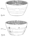
- Fig. 2A shows a bowl and basket assembly according to a first embodiment of the present invention, generally designated as 100
- Fig. 2B shows a bowl and basket assembly according to a second embodiment of the present invention, generally designated as 200.
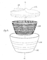
- the basket and bowl assembly 100 includes an outer bowl 102 receiving a perforated inner basket 104.
- the bowl 102 has a generally upstanding wall 106 and a bottom 108 (see Fig. 8 ) from which a protrusion 110 extends upwardly (see Fig. 7 ).
- the bottom of the basket 104 sits on the protrusion 110 such that the basket 104 may be caused to rotate relative to the bowl 102 about a common longitudinal axis M-M.
- a cover 112 (shown in dotted lines) may be provided for covering the upper open end of the bowl 102 and that of the basket 104 for forming a salad spinner.
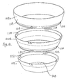
- the bowl 102 includes a top body part 102a, a middle body part 102b, and a bottom body part 102c.
- the top body part 102a has an annular upstanding wall 114 along an outer surface of a lower end of which are provided four rectangular protrusions 116 (of which only two are shown in Fig. 4 ).
- As to the middle body part 102b along an inner surface of an upper edge of which are provided four generally L-shaped recesses 118 each for receiving one of the protrusions 116.
- four rectangular protrusions 120 (of which only two are shown in Fig. 4 ).
- For the bottom body part 102c along an inner surface of an upper edge of which are provided four generally L-shaped recesses 122 each for receiving one of the protrusions 120.
- the middle body part 102b is first releasably engaged with and on the bottom body part 102c, and the bop body part 102a is then releasably engaged with and on the middle body part 102b.
- the top body part 102a is shown as being about to be engaged with the middle body part 102b, and the middle body part 102b is shown as being engaged with the bottom body part 102c.
- the top body part 102a carries an O-ring 124a, which may be made of silicone rubber, for providing water-proof sealing between the top body part 102a and the middle body part 102b when they are engaged with each other.
- the middle body part 102b also carries a silicone rubber O-ring 124b for providing water-proof sealing between the middle body part 102b and the bottom body part 120c when they are engaged with each other.
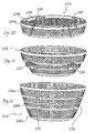
- Figs. 10 to 12 show various configurations in which the basket 104 of the bowl and basket assembly 100 may assume.
- Fig. 10 shows a fully collapsed configuration
- Fig. 11 shows a partially expanded configuration
- Fig. 12 shows a fully expanded configuration.
- a top body part 104a sits on a middle body part 104b, which in turn sits on a bottom body part 104c.
- the three body parts 104a, 104b, 104c are on the same level and generally concentric with one another.
- the middle body part 104b is within the top body part 104a
- the bottom body part 104c is in the innermost position, i.e. it is within the middle body part 104b.
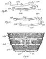
- the body parts 104a, 104b, 104c are always connected with one another by four links 126. As shown in Figs. 13 to 16 , during movement of the body parts 104a, 104b, 104c between the fully collapsed configuration (as shown in Fig. 13 ) to the fully expanded configuration (as shown in Fig. 16 ), the links 126 slide and rotate relative to the top body part 104a and the bottom body part 104c, and the links 126 only rotate relative to the middle body part 104b.
- each of the links 126 has two parallel slots 128a, 128b and a through-hole 130.
- the slot 128a receives a pin 132a carried by the top body part 104a for relative sliding and rotational movement;
- the slot 128b receives a pin 132b carried by the bottom body part 104c for relative sliding and rotational movement;
- the through-hole 130 receives a pin 132c for relative rotational movement.
- the body parts 104a, 104b, 104c may be manipulated to move between the fully collapsed configuration and the fully expanded configuration.
- the links 126 are kept at the positions as shown in Fig.
- the basket 104 may thus remain in the fully expanded configuration as shown in Fig. 12 .
- the links 126 may be manually displaced from the positions as shown in Fig. 16 so as to move the body parts 104a, 104b, 104c to the fully collapsed configuration as shown in Fig. 10 .
- Fig. 19 shows an exploded bottom perspective view of the cover and driving mechanism assembly 112 shown in Fig. 3 , forming part of a salad spinner.
- the assembly 112 includes a cover 136 for releasably engaging with and covering the bowl 102.
- the cover 136 has a housing 140 containing a transmission mechanism with an output spindle 142 for engagement with a hole 144 of a top 138. Upon rotational of the output spindle 142 about its longitudinal axis, the top 138 will be brought into simultaneous rotational movement about the same axis.
- a manually operable lever 146 which may be pivoted to and fro to cause the spindle 142 to rotate about its longitudinal axis in one direction, thus causing the top 138 to exhibit rotational movement in like manner.
- the top 138 has three hingedly engaged wings 148 which may be pivoted about a respective axis (all being perpendicular to the longitudinal axis of the top 138) between the extended position as shown in Fig. 19 and the folded position as shown in Fig. 20 .
- the assembly 112 When in the extended position as shown in Fig. 19 , the assembly 112 may be placed on the bowl and basket assembly 100 and operated to impart rotational movement to the basket 104 relative to the bowl 102 about the axis M-M.
- each wing 148 has a toe 150 which, when the assembly 112 is placed on the bowl and basket assembly 100, engages with a respective perforation in the basket 104 for bringing the basket 104 into simultaneous rotational movement.
- the components forming a salad spinner including the bowl and basket assembly 100 may form a kit, as shown in Fig. 21 , and be further packaged as shown in Figs. 22 and 23 , with a height of X. It can be clearly seen in Fig. 24 that, while the volume of the bowl and basket assembly 100, when assembled, is no less than that of the conventional bowl and basket assembly 10 of Figs.
- a salad spinner including the conventional bowl and basket assembly 10 and a cover 20, when packaged, will be of a height of Y + Z
- a salad spinner including the bowl and basket assembly 100 according to a first embodiment of the present invention and including the cover and driving mechanism assembly 112, when packaged, will be of a height of X, which is significantly smaller than Y + Z.
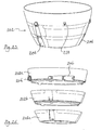
- Fig. 25 shows a bowl 202 of the bowl and basket assembly 200 of Fig. 2B .
- the bowl 202 is made up of a top body part 202a, a middle body part 202b and a bottom body part 202c.
- the top body part 202a carries three clasps 206, of which only two are shown in Figs. 25 and 26 .
- the clasps 206 span from the top body part 202a, and across the middle body part 202b and the bottom body part 202c.
- each clasp 206 has an ear 208 pivotally engaged with an inner arm 210, which is in turn pivotally engaged with an outer arm 212.
- the ear 208 is engaged, via a bolt 214, with the top body part 202a for rotational movement relative to the top body part 202a about the axis T-T.
- the clasps 206 may be extended across the body parts 202a, 202b, 202c, and be releasably engaged with the body parts 202b, 202c for assembling the bowl 202.
- a perforated basket 204 of the bowl and basket assembly 200 is shown in Fig. 32 in its fully expanded configuration.
- the basket 204 has three body parts, namely a top body part 204a, a middle body part 204b, and a bottom body part 204c.
- the top body part 204a sits on the middle body part 204b, which in turn sits on the bottom body part 204c.
- the middle body part 204b is shown in Fig. 33 .
- the structure of the basket 204 is basically the same as that of the basket 104 of the bowl and basket assembly 100 discussed above.
- the body parts 204a, 204b, 204c are also always connected with one another by a number of links 205.
- the main difference resides in a number of locks 220a, 220b carried by the middle body part 204b of the basket 204.
- the locks 220a, 220b are made of a resilient material, e.g. plastics, which allows the locks 220a, 220b to deform to perform the locking and unlocking functions, to be discussed below.
- the lock 220a has a hand-operable portion 222 from which a pair of curved and parallel arms 224a, 224b extend. At the free end of each of the arms 224a, 224b is a protrusion 226a, 226b, and the protrusions 226a, 226b extend towards opposite directions.
- the lock 220b has a hand-operable portion 228 from which a pair of curved and parallel arms 230a, 230b extend. At the free end of each of the arms 230a, 230b is a protrusion 232a, 232b, and the protrusions 232a, 232b extend towards opposite directions.
- Figs. 37 to 40 it can be seen that when at the fully expanded configuration, the protrusion 226a of the arm 224a of the lock 220a abuts a lower edge of the top body part 204a, and the protrusion 226b of the arm 224b abuts an upper edge of the bottom body part 204c.
- the lock 220b is similarly positioned relative to the top body part 204a, the middle body part 204b, and the bottom body part 204c.
- the hand-operable portion 228 of the lock 220a may be moved in the direction indicated by the arrow G in Fig. 38 to deform the lock 220a, against a fixed rib 250 of the middle body part 204b.
- the protrusion 226a is moved out of abutment with the lower edge of the top body part 204a, as shown in Fig. 39 , until it is below a recess 252 of the top body part 204a, whereupon the top body part 204a may move downwardly relative to the middle body part 204b.
- the protrusion 226b is also moved out of abutment with the upper edge of the bottom body part 204c, thus allowing the middle body part 204b to move downwardly relative to the bottom body part 204c.
- the lock 220a will return, by reason of its own resilience, from its deformed contracted configuration to its stable extended configuration.
- the bowl 102 and the basket 204 may form a bowl and basket assembly, which may form part of a salad spinner.
- the bowl 202 and the basket 104 may form a bowl and basket assembly, which may form part of a salad spinner. It can also be seen that as the parts of the bowl and basket assemblies 100, 200 are easily assembled and disassembled, these may be provided and sold in a kit form, allowing users to assemble and disassemble the assemblies 100, 200 themselves.
Landscapes
- Engineering & Computer Science (AREA)
- Mechanical Engineering (AREA)
- Food Science & Technology (AREA)
- Food-Manufacturing Devices (AREA)
- Centrifugal Separators (AREA)
- Preparation Of Fruits And Vegetables (AREA)
Claims (30)
- Schüssel- und Korbanordnung (100, 200), die umfasst:einen perforierten Korb (104, 204); undeine Schüssel (102, 202) für das Aufnehmen des Korbes;wobei der Korb ein erstes Körperelement (104a, 204a) und ein zweites Körperelement (104b, 204b) umfasst, die miteinander mittels mindestens eines Verbindungselementes (126, 205) verbunden sind,und wobei die Körperelemente relativ zueinander zwischen einer ersten Konfiguration, in der das erste Körperelement auf dem zweiten Körperelement aufliegt, und einer zweiten Konfiguration beweglich sind, in der sich das zweite Körperelement innerhalb des ersten Körperelementes befindet;dadurch gekennzeichnet, dass der Korb mindestens ein drittes Körperelement (104c, 204c) umfasst, das mittels des Verbindungselementes mit dem ersten und zweiten Körperelement verbunden ist.
- Anordnung nach Anspruch 1, außerdem dadurch gekennzeichnet, dass das erste und zweite Körperelement mittels einer Vielzahl von Verbindungselementen miteinander verbunden sind.
- Anordnung nach Anspruch 1, außerdem dadurch gekennzeichnet, dass das erste, zweite und dritte Körperelement mittels einer Vielzahl von Verbindungselementen miteinander verbunden sind.
- Anordnung nach Anspruch 1, außerdem dadurch gekennzeichnet, dass das erste, zweite und dritte Körperelement relativ zueinander zwischen einer ersten Konfiguration, in der das erste Körperelement auf dem zweiten Körperelement aufliegt, und das zweite Körperelement auf dem dritten Körperelement aufliegt, und einer zweiten Konfiguration beweglich sind, in der sich das zweite Körperelement innerhalb des ersten Körperelementes befindet und sich das dritte Körperelement innerhalb des zweiten Körperelementes befindet.
- Anordnung nach Anspruch 4, außerdem dadurch gekennzeichnet, dass das Verbindungselement relativ zum ersten und dritten Körperelement während der Bewegung des ersten, zweiten und dritten Körperelementes zwischen der ersten und zweiten Konfiguration verschiebbar und drehbar ist.
- Anordnung nach Anspruch 5, außerdem dadurch gekennzeichnet, dass das Verbindungselement einen ersten Schlitz (128a) und einen zweiten Schlitz (128b) aufweist, die parallel zueinander sind, wobei der erste Schlitz mit mindestens einem Stift (132a) des ersten Körperelementes für eine relative Verschiebe- und Drehbewegung in Eingriff kommt, und wobei der zweite Schlitz mit mindestens einem Stift (132b) des dritten Körperelementes für eine relative Verschiebe- und Drehbewegung in Eingriff kommt.
- Anordnung nach Anspruch 4, außerdem dadurch gekennzeichnet, dass das Verbindungselement relativ zum zweiten Körperelement während der Bewegung des ersten, zweiten und dritten Körperelementes zwischen der ersten und zweiten Konfiguration drehbar ist.
- Anordnung nach Anspruch 7, außerdem dadurch gekennzeichnet, dass das Verbindungselement ein Loch (130) für das Aufnehmen von mindestens einem Stift (132c) des zweiten Körperelementes für eine relative Drehbewegung aufweist.
- Anordnung nach Anspruch 1, außerdem dadurch gekennzeichnet, dass sie eine Verriegelungseinrichtung (220a, 220b) umfasst, die zwischen einer ersten Konfiguration, bei der die Bewegung der Körperelemente aus der ersten Konfiguration in die zweite Konfiguration verhindert wird, und einer zweiten Konfiguration beweglich ist, in der die Bewegung der Körperelemente aus der ersten Konfiguration in die zweite Konfiguration gestattet wird.
- Anordnung nach Anspruch 9, außerdem dadurch gekennzeichnet, dass die Verriegelungseinrichtung in Richtung der ersten Konfiguration vorgespannt wird.
- Anordnung nach Anspruch 9, außerdem dadurch gekennzeichnet, dass die Verriegelungseinrichtung elastisch ist.
- Anordnung nach Anspruch 4, außerdem dadurch gekennzeichnet, dass sie eine Verriegelungseinrichtung umfasst, die zwischen einer ersten Konfiguration, bei der die Bewegung des ersten, zweiten und dritten Körperelementes aus der ersten Konfiguration in die zweite Konfiguration verhindert wird, und einer zweiten Konfiguration beweglich ist, in der die Bewegung des ersten, zweiten und dritten Körperelementes aus der ersten Konfiguration in die zweite Konfiguration gestattet wird.
- Anordnung nach Anspruch 12, außerdem dadurch gekennzeichnet, dass die Verriegelungseinrichtung mindestens ein Paar Verriegelungselemente (220a, 220b) umfasst, die vom zweiten Körperelement getragen werden.
- Anordnung nach Anspruch 13, außerdem dadurch gekennzeichnet, dass das zweite Körperelement mindestens zwei Paar der Verriegelungselemente trägt.
- Anordnung nach Anspruch 13, außerdem dadurch gekennzeichnet, dass jedes Verriegelungselement erste und zweite Armelemente (224a, 224b, 230a, 230b) umfasst, die parallel zueinander sind.
- Anordnung nach Anspruch 15, außerdem dadurch gekennzeichnet, dass das erste Armelement ein Anschlagelement (226a, 232a) trägt, das, wenn sich die Verriegelungseinrichtung in der ersten Konfiguration befindet, an einen unteren Rand eines Wandelementes des ersten Körperelementes anstößt.
- Anordnung nach Anspruch 16, außerdem dadurch gekennzeichnet, dass, wenn sich die Verriegelungseinrichtung in der zweiten Konfiguration befindet, das Anschlagelement des ersten Armelementes nicht an den unteren Rand des Wandelementes des ersten Körperelementes anstößt.
- Anordnung nach Anspruch 15, außerdem dadurch gekennzeichnet, dass das zweite Armelement ein Anschlagelement (226b 232b trägt, das, wenn sich die Verriegelungseinrichtung in der ersten Konfiguration befindet, an einen oberen Rand eines Wandelementes des dritten Körperelementes anstößt.
- Anordnung nach Anspruch 18, außerdem dadurch gekennzeichnet, dass, wenn sich die Verriegelungseinrichtung in der zweiten Konfiguration befindet, das Anschlagelement des zweiten Armelementes nicht an den oberen Rand des Wandelementes des dritten Körperelementes anstößt.
- Anordnung nach Anspruch 1, außerdem dadurch gekennzeichnet, dass die Schüssel mindestens ein erstes Körperelement (102b, 202b) und ein zweites Körperelement (102c, 202c) umfasst, die lösbar miteinander in Eingriff sind.
- Anordnung nach Anspruch 20, außerdem dadurch gekennzeichnet, dass das erste Körperelement der Schüssel mindestens ein drehbar bewegliches Klammerelement (210) trägt.
- Anordnung nach Anspruch 21, außerdem dadurch gekennzeichnet, dass das Klammerelement lösbar mit dem zweiten Körperelement der Schüssel für einen lösbaren Eingriff des ersten Körperelementes der Schüssel mit dem zweiten Körperelement der Schüssel in Eingriff kommt.
- Anordnung nach Anspruch 20, außerdem dadurch gekennzeichnet, dass die Schüssel mindestens ein erstes Körperelement (102a, 202a), ein zweites Körperelement (102b, 202b) und ein drittes Körperelement (102c, 202c) umfasst, die lösbar miteinander in Eingriff kommen.
- Anordnung nach Anspruch 23, außerdem dadurch gekennzeichnet, dass das erste Körperelement der Schüssel mindestens ein drehbar bewegliches Klammerelement trägt, und dass das Klammerelement lösbar mit dem zweiten und dritten Körperelement der Schüssel für einen lösbaren Eingriff des ersten Körperelementes der Schüssel mit dem zweiten und dritten Körperelement der Schüssel in Eingriff kommt.
- Anordnung nach Anspruch 20, außerdem dadurch gekennzeichnet, dass am oder benachbart einem freien Ende der Klammer ein Eingriffselement für das lösbare Eingreifen eines Wandelementes des ersten Körperelementes der Schüssel vorhanden ist.
- Salatschleuder, die eine Schüssel- und Korbanordnung nach Anspruch 1 umfasst.
- Salatschleuder nach Anspruch 26, außerdem dadurch gekennzeichnet, dass sie ein Deckelelement für das lösbare Abdecken eines offenen Endes des Korbes und eines offenen Endes der Schüssel umfasst.
- Salatschleuder nach Anspruch 27, außerdem dadurch gekennzeichnet, dass das Deckelelement einen Antriebsmechanismus umfasst, der ausgebildet ist, um den Korb in einer Drehbewegung relativ zur Schüssel um eine im Wesentlichen gemeinsame Längsachse anzutreiben.
- Salatschleuder nach Anspruch 28, außerdem dadurch gekennzeichnet, dass der Antriebsmechanismus eine Einrichtung für das lösbare Eingreifen in mindestens eine Perforation des Korbes für die gleichzeitige Drehbewegung relativ zur Schüssel umfasst.
- Salatschleuder nach Anspruch 29, außerdem dadurch gekennzeichnet, dass die lösbare Eingriffseinrichtung durch mindestens ein Flügelelement getragen wird, das drehbar zwischen einer ausgezogenen Position und einer zusammengeklappten Position beweglich ist.
Priority Applications (7)
| Application Number | Priority Date | Filing Date | Title |
|---|---|---|---|
| AT07252615T ATE550978T1 (de) | 2007-06-28 | 2007-06-28 | Schüssel- und korbanordnung sowie salatschleuder mit einer solchen korbanordnung |
| EP07252615A EP2008560B1 (de) | 2007-06-28 | 2007-06-28 | Schüssel- und Korbanordnung sowie Salatschleuder mit einer solchen Korbanordnung |
| CA2602253A CA2602253C (en) | 2007-06-28 | 2007-09-17 | Bowl and basket assembly and salad spinner incorporating such an assembly |
| US11/857,230 US7921769B2 (en) | 2007-06-28 | 2007-09-18 | Bowl and basket and salad spinner incorporating such an assembly |
| JP2007270904A JP2009006115A (ja) | 2007-06-28 | 2007-10-18 | ボウル・バスケット組立体およびそのような組立体を組み入れるサラダスピナー |
| CNA2007101653700A CN101332053A (zh) | 2007-06-28 | 2007-10-26 | 碗篮组件以及结合有该组件的蔬菜脱水器 |
| HK09105829.7A HK1127908B (en) | 2009-06-29 | Bowl and basket assembly and salad spinner incorporating such an assembly |
Applications Claiming Priority (1)
| Application Number | Priority Date | Filing Date | Title |
|---|---|---|---|
| EP07252615A EP2008560B1 (de) | 2007-06-28 | 2007-06-28 | Schüssel- und Korbanordnung sowie Salatschleuder mit einer solchen Korbanordnung |
Publications (2)
| Publication Number | Publication Date |
|---|---|
| EP2008560A1 EP2008560A1 (de) | 2008-12-31 |
| EP2008560B1 true EP2008560B1 (de) | 2012-03-28 |
Family
ID=38983321
Family Applications (1)
| Application Number | Title | Priority Date | Filing Date |
|---|---|---|---|
| EP07252615A Not-in-force EP2008560B1 (de) | 2007-06-28 | 2007-06-28 | Schüssel- und Korbanordnung sowie Salatschleuder mit einer solchen Korbanordnung |
Country Status (6)
| Country | Link |
|---|---|
| US (1) | US7921769B2 (de) |
| EP (1) | EP2008560B1 (de) |
| JP (1) | JP2009006115A (de) |
| CN (1) | CN101332053A (de) |
| AT (1) | ATE550978T1 (de) |
| CA (1) | CA2602253C (de) |
Cited By (1)
| Publication number | Priority date | Publication date | Assignee | Title |
|---|---|---|---|---|
| USD706075S1 (en) | 2013-01-29 | 2014-06-03 | Progressive International Corporation | Salad spinner lid |
Families Citing this family (26)
| Publication number | Priority date | Publication date | Assignee | Title |
|---|---|---|---|---|
| AU2007336481B2 (en) * | 2006-12-21 | 2014-06-05 | Chef'n Corporation | Food processing system |
| AU2007357858B2 (en) * | 2007-08-17 | 2014-05-22 | Sea To Summit Pty Ltd | Collapsible container |
| US20100083847A1 (en) * | 2008-10-06 | 2010-04-08 | Phillip Kirschbaum | Salad Spinning Assembly |
| US8215230B2 (en) | 2008-12-05 | 2012-07-10 | Progressive International Corporation | Collapsible salad spinner |
| USD629264S1 (en) | 2008-12-31 | 2010-12-21 | Progressive International Corporation | Collapsible salad spinner bowl |
| US9345363B2 (en) * | 2009-04-02 | 2016-05-24 | Timothy C. Repp | Salad spinner with angled blade fan |
| US9259014B2 (en) | 2010-02-11 | 2016-02-16 | Brinee Home Solution Ltd. | Food products serving and preserving device |
| MX2013000557A (es) | 2010-07-16 | 2013-05-30 | Amcor Ltd | Rebaba de base controlada que forma un anillo de pie. |
| USD651476S1 (en) | 2011-02-05 | 2012-01-03 | Progressive International Corporation | Collapsible produce keeper |
| USD669318S1 (en) | 2012-01-26 | 2012-10-23 | Progressive International Corporation | Collapsible container |
| CN104116425B (zh) * | 2013-04-24 | 2016-08-10 | 曾世贞 | 旋动式清洗沥水篮组 |
| USD731862S1 (en) | 2014-01-30 | 2015-06-16 | Progessive International Corporation | Collapsible colander |
| USD731260S1 (en) | 2014-01-30 | 2015-06-09 | Progressive International Corporation | Collapsible colander |
| USD732354S1 (en) | 2014-01-30 | 2015-06-23 | Progressive International Corporation | Collapsible colander |
| USD746640S1 (en) | 2014-01-31 | 2016-01-05 | Progressive International Corporation | Collapsible storage bowl |
| USD731261S1 (en) | 2014-02-03 | 2015-06-09 | Progressive International Corporation | Collapsible over the sink colander |
| US9427136B2 (en) | 2014-04-22 | 2016-08-30 | Progressive International Corporation | Collapsible dish drainer |
| USD754495S1 (en) | 2014-09-25 | 2016-04-26 | Progressive International Corporation | Colander |
| USD766530S1 (en) | 2015-02-04 | 2016-09-13 | Progressive International Corporation | Collapsible dish drainer |
| US11051646B2 (en) * | 2016-01-14 | 2021-07-06 | Jmm Visionary, Llc | Cooking apparatus |
| JP6412668B1 (ja) * | 2017-06-12 | 2018-10-24 | 収美 野村 | 水切り容器および水切り容器用台座 |
| CN109276168A (zh) * | 2018-10-15 | 2019-01-29 | 齐双莲 | 一种厨房用沥水器 |
| CN110448209A (zh) * | 2019-08-06 | 2019-11-15 | 浙江机电职业技术学院 | 一种沥水时可自立的砧板 |
| US12060195B2 (en) | 2021-07-01 | 2024-08-13 | Instant Brands Holdings Inc. | Containers |
| KR20240023436A (ko) | 2021-09-27 | 2024-02-21 | 인스턴트 브랜즈 홀딩스 인크. | 용기 |
| USD1035397S1 (en) * | 2023-05-13 | 2024-07-16 | Congqiang Lu | Salad spinner |
Family Cites Families (11)
| Publication number | Priority date | Publication date | Assignee | Title |
|---|---|---|---|---|
| FR384179A (fr) | 1906-11-27 | 1908-03-31 | Johannes Piat | Carburateur pour moteurs à explosion |
| FR829700A (fr) | 1937-11-22 | 1938-07-04 | Perfectionnement apporté dans l'établissement des paniers à secouer la salade, essorer les légumes ou autres produits | |
| US4040460A (en) * | 1975-12-23 | 1977-08-09 | Sidney Thornton | Collapsible bucket |
| FR2643553B1 (fr) | 1989-02-24 | 1993-04-09 | Moulinex Sa | Essoreuse |
| US5064535A (en) | 1990-10-25 | 1991-11-12 | Hsu Chun Feng | Strainer for washed vegetables |
| US5662026A (en) * | 1995-06-01 | 1997-09-02 | P.T. Maspion | Clip system for cookware |
| ITMI20020663A1 (it) * | 2002-03-29 | 2003-09-29 | Dms Distrib Marketing Service | Scolapasta ad ingombro ridotto |
| US7654402B2 (en) * | 2003-12-16 | 2010-02-02 | Dart Industries Inc. | Collapsible container |
| US7080463B1 (en) | 2004-08-04 | 2006-07-25 | Robert A Johnson | Food drying, mixing and serving apparatus |
| ES2299973T3 (es) * | 2005-12-08 | 2008-06-01 | Clever Edge, Inc. | Filtro. |
| US20080164264A1 (en) * | 2006-10-31 | 2008-07-10 | Fung Duncan C | Foldable stovetop cookware and method of production |
-
2007
- 2007-06-28 EP EP07252615A patent/EP2008560B1/de not_active Not-in-force
- 2007-06-28 AT AT07252615T patent/ATE550978T1/de active
- 2007-09-17 CA CA2602253A patent/CA2602253C/en not_active Expired - Fee Related
- 2007-09-18 US US11/857,230 patent/US7921769B2/en not_active Expired - Fee Related
- 2007-10-18 JP JP2007270904A patent/JP2009006115A/ja not_active Withdrawn
- 2007-10-26 CN CNA2007101653700A patent/CN101332053A/zh active Pending
Cited By (1)
| Publication number | Priority date | Publication date | Assignee | Title |
|---|---|---|---|---|
| USD706075S1 (en) | 2013-01-29 | 2014-06-03 | Progressive International Corporation | Salad spinner lid |
Also Published As
| Publication number | Publication date |
|---|---|
| CA2602253C (en) | 2014-04-15 |
| US20090000981A1 (en) | 2009-01-01 |
| US7921769B2 (en) | 2011-04-12 |
| EP2008560A1 (de) | 2008-12-31 |
| HK1127908A1 (en) | 2009-10-09 |
| ATE550978T1 (de) | 2012-04-15 |
| CN101332053A (zh) | 2008-12-31 |
| JP2009006115A (ja) | 2009-01-15 |
| CA2602253A1 (en) | 2008-12-28 |
Similar Documents
| Publication | Publication Date | Title |
|---|---|---|
| CA2602253C (en) | Bowl and basket assembly and salad spinner incorporating such an assembly | |
| KR101527427B1 (ko) | 삼중 절첩식 유모차 | |
| US8746794B2 (en) | Infant bouncer | |
| US5865109A (en) | Drive mechanism | |
| ES2692330T3 (es) | Contenedor plegable | |
| CN209346665U (zh) | 一种烹饪器具 | |
| US20090127298A1 (en) | Collapsible Garment Hanger | |
| EP1442681A1 (de) | Zusammenklappbarer Kinderlaufstall mit Verriegelungssvorrichtung | |
| JP5564103B2 (ja) | 畳んで引き込み可能な翼を持った玩具 | |
| US6477732B1 (en) | Folding bristle hairbrush | |
| KR101794448B1 (ko) | 소프트박스용 원터치 폴딩 스피드링 | |
| HK1005424A1 (en) | A collapsible mop pad holder, a combination comprising a collapsible mop pad holder and a mop pad mounted thereto, and a mop pad holder and a mop pad for use in the combination | |
| EP2062515B1 (de) | Schüssel- und Korbanordnung sowie Salatschleuder mit einer solchen Korbanordnung | |
| JP2016527008A (ja) | 調理容器用着脱式両手取っ手 | |
| HK1127908B (en) | Bowl and basket assembly and salad spinner incorporating such an assembly | |
| GB1575183A (en) | Chopping device for comminuting foodstuffs | |
| CN212744684U (zh) | 具有二道锁的折叠结构及婴儿床 | |
| KR200447313Y1 (ko) | 절첩식 포켓용 뜰채 | |
| US6539847B2 (en) | Food processing device | |
| CN214710984U (zh) | 一种电热饭盒 | |
| KR20200057412A (ko) | 접이용 뚜껑 손잡이 | |
| CN217039898U (zh) | 一种折叠式足浴器 | |
| KR200334318Y1 (ko) | 걸림수단이 장착된 양면 후라이팬 | |
| CN107788830B (zh) | 烹饪锅具 | |
| CN215820642U (zh) | 用于烹饪器具的门体结构和烹饪器具 |
Legal Events
| Date | Code | Title | Description |
|---|---|---|---|
| PUAI | Public reference made under article 153(3) epc to a published international application that has entered the european phase |
Free format text: ORIGINAL CODE: 0009012 |
|
| AK | Designated contracting states |
Kind code of ref document: A1 Designated state(s): AT BE BG CH CY CZ DE DK EE ES FI FR GB GR HU IE IS IT LI LT LU LV MC MT NL PL PT RO SE SI SK TR |
|
| AX | Request for extension of the european patent |
Extension state: AL BA HR MK RS |
|
| 17P | Request for examination filed |
Effective date: 20090616 |
|
| AKX | Designation fees paid |
Designated state(s): AT BE BG CH CY CZ DE DK EE ES FI FR GB GR HU IE IS IT LI LT LU LV MC MT NL PL PT RO SE SI SK TR |
|
| REG | Reference to a national code |
Ref country code: HK Ref legal event code: DE Ref document number: 1127908 Country of ref document: HK |
|
| GRAP | Despatch of communication of intention to grant a patent |
Free format text: ORIGINAL CODE: EPIDOSNIGR1 |
|
| GRAS | Grant fee paid |
Free format text: ORIGINAL CODE: EPIDOSNIGR3 |
|
| GRAA | (expected) grant |
Free format text: ORIGINAL CODE: 0009210 |
|
| RIN1 | Information on inventor provided before grant (corrected) |
Inventor name: SO, KWOK KUEN Inventor name: WAN, YIU CHUNG |
|
| AK | Designated contracting states |
Kind code of ref document: B1 Designated state(s): AT BE BG CH CY CZ DE DK EE ES FI FR GB GR HU IE IS IT LI LT LU LV MC MT NL PL PT RO SE SI SK TR |
|
| REG | Reference to a national code |
Ref country code: GB Ref legal event code: FG4D |
|
| REG | Reference to a national code |
Ref country code: CH Ref legal event code: EP |
|
| REG | Reference to a national code |
Ref country code: AT Ref legal event code: REF Ref document number: 550978 Country of ref document: AT Kind code of ref document: T Effective date: 20120415 |
|
| REG | Reference to a national code |
Ref country code: IE Ref legal event code: FG4D |
|
| REG | Reference to a national code |
Ref country code: DE Ref legal event code: R096 Ref document number: 602007021586 Country of ref document: DE Effective date: 20120524 |
|
| REG | Reference to a national code |
Ref country code: NL Ref legal event code: VDEP Effective date: 20120328 |
|
| PG25 | Lapsed in a contracting state [announced via postgrant information from national office to epo] |
Ref country code: LT Free format text: LAPSE BECAUSE OF FAILURE TO SUBMIT A TRANSLATION OF THE DESCRIPTION OR TO PAY THE FEE WITHIN THE PRESCRIBED TIME-LIMIT Effective date: 20120328 |
|
| LTIE | Lt: invalidation of european patent or patent extension |
Effective date: 20120328 |
|
| PG25 | Lapsed in a contracting state [announced via postgrant information from national office to epo] |
Ref country code: FI Free format text: LAPSE BECAUSE OF FAILURE TO SUBMIT A TRANSLATION OF THE DESCRIPTION OR TO PAY THE FEE WITHIN THE PRESCRIBED TIME-LIMIT Effective date: 20120328 Ref country code: LV Free format text: LAPSE BECAUSE OF FAILURE TO SUBMIT A TRANSLATION OF THE DESCRIPTION OR TO PAY THE FEE WITHIN THE PRESCRIBED TIME-LIMIT Effective date: 20120328 Ref country code: GR Free format text: LAPSE BECAUSE OF FAILURE TO SUBMIT A TRANSLATION OF THE DESCRIPTION OR TO PAY THE FEE WITHIN THE PRESCRIBED TIME-LIMIT Effective date: 20120629 |
|
| PGFP | Annual fee paid to national office [announced via postgrant information from national office to epo] |
Ref country code: GB Payment date: 20120619 Year of fee payment: 6 |
|
| REG | Reference to a national code |
Ref country code: AT Ref legal event code: MK05 Ref document number: 550978 Country of ref document: AT Kind code of ref document: T Effective date: 20120328 |
|
| PG25 | Lapsed in a contracting state [announced via postgrant information from national office to epo] |
Ref country code: CY Free format text: LAPSE BECAUSE OF FAILURE TO SUBMIT A TRANSLATION OF THE DESCRIPTION OR TO PAY THE FEE WITHIN THE PRESCRIBED TIME-LIMIT Effective date: 20120328 |
|
| REG | Reference to a national code |
Ref country code: HK Ref legal event code: GR Ref document number: 1127908 Country of ref document: HK |
|
| PG25 | Lapsed in a contracting state [announced via postgrant information from national office to epo] |
Ref country code: SI Free format text: LAPSE BECAUSE OF FAILURE TO SUBMIT A TRANSLATION OF THE DESCRIPTION OR TO PAY THE FEE WITHIN THE PRESCRIBED TIME-LIMIT Effective date: 20120328 Ref country code: IS Free format text: LAPSE BECAUSE OF FAILURE TO SUBMIT A TRANSLATION OF THE DESCRIPTION OR TO PAY THE FEE WITHIN THE PRESCRIBED TIME-LIMIT Effective date: 20120728 Ref country code: CZ Free format text: LAPSE BECAUSE OF FAILURE TO SUBMIT A TRANSLATION OF THE DESCRIPTION OR TO PAY THE FEE WITHIN THE PRESCRIBED TIME-LIMIT Effective date: 20120328 Ref country code: BE Free format text: LAPSE BECAUSE OF FAILURE TO SUBMIT A TRANSLATION OF THE DESCRIPTION OR TO PAY THE FEE WITHIN THE PRESCRIBED TIME-LIMIT Effective date: 20120328 Ref country code: SE Free format text: LAPSE BECAUSE OF FAILURE TO SUBMIT A TRANSLATION OF THE DESCRIPTION OR TO PAY THE FEE WITHIN THE PRESCRIBED TIME-LIMIT Effective date: 20120328 Ref country code: EE Free format text: LAPSE BECAUSE OF FAILURE TO SUBMIT A TRANSLATION OF THE DESCRIPTION OR TO PAY THE FEE WITHIN THE PRESCRIBED TIME-LIMIT Effective date: 20120328 Ref country code: RO Free format text: LAPSE BECAUSE OF FAILURE TO SUBMIT A TRANSLATION OF THE DESCRIPTION OR TO PAY THE FEE WITHIN THE PRESCRIBED TIME-LIMIT Effective date: 20120328 Ref country code: PL Free format text: LAPSE BECAUSE OF FAILURE TO SUBMIT A TRANSLATION OF THE DESCRIPTION OR TO PAY THE FEE WITHIN THE PRESCRIBED TIME-LIMIT Effective date: 20120328 |
|
| PG25 | Lapsed in a contracting state [announced via postgrant information from national office to epo] |
Ref country code: PT Free format text: LAPSE BECAUSE OF FAILURE TO SUBMIT A TRANSLATION OF THE DESCRIPTION OR TO PAY THE FEE WITHIN THE PRESCRIBED TIME-LIMIT Effective date: 20120730 Ref country code: SK Free format text: LAPSE BECAUSE OF FAILURE TO SUBMIT A TRANSLATION OF THE DESCRIPTION OR TO PAY THE FEE WITHIN THE PRESCRIBED TIME-LIMIT Effective date: 20120328 |
|
| PGFP | Annual fee paid to national office [announced via postgrant information from national office to epo] |
Ref country code: DE Payment date: 20120625 Year of fee payment: 6 Ref country code: FR Payment date: 20120718 Year of fee payment: 6 |
|
| PG25 | Lapsed in a contracting state [announced via postgrant information from national office to epo] |
Ref country code: DK Free format text: LAPSE BECAUSE OF FAILURE TO SUBMIT A TRANSLATION OF THE DESCRIPTION OR TO PAY THE FEE WITHIN THE PRESCRIBED TIME-LIMIT Effective date: 20120328 Ref country code: NL Free format text: LAPSE BECAUSE OF FAILURE TO SUBMIT A TRANSLATION OF THE DESCRIPTION OR TO PAY THE FEE WITHIN THE PRESCRIBED TIME-LIMIT Effective date: 20120328 Ref country code: AT Free format text: LAPSE BECAUSE OF FAILURE TO SUBMIT A TRANSLATION OF THE DESCRIPTION OR TO PAY THE FEE WITHIN THE PRESCRIBED TIME-LIMIT Effective date: 20120328 Ref country code: MC Free format text: LAPSE BECAUSE OF NON-PAYMENT OF DUE FEES Effective date: 20120630 |
|
| REG | Reference to a national code |
Ref country code: CH Ref legal event code: PL |
|
| PLBE | No opposition filed within time limit |
Free format text: ORIGINAL CODE: 0009261 |
|
| STAA | Information on the status of an ep patent application or granted ep patent |
Free format text: STATUS: NO OPPOSITION FILED WITHIN TIME LIMIT |
|
| REG | Reference to a national code |
Ref country code: CH Ref legal event code: PL |
|
| PG25 | Lapsed in a contracting state [announced via postgrant information from national office to epo] |
Ref country code: IT Free format text: LAPSE BECAUSE OF FAILURE TO SUBMIT A TRANSLATION OF THE DESCRIPTION OR TO PAY THE FEE WITHIN THE PRESCRIBED TIME-LIMIT Effective date: 20120328 |
|
| 26N | No opposition filed |
Effective date: 20130103 |
|
| REG | Reference to a national code |
Ref country code: IE Ref legal event code: MM4A |
|
| REG | Reference to a national code |
Ref country code: DE Ref legal event code: R097 Ref document number: 602007021586 Country of ref document: DE Effective date: 20130103 |
|
| PG25 | Lapsed in a contracting state [announced via postgrant information from national office to epo] |
Ref country code: IE Free format text: LAPSE BECAUSE OF NON-PAYMENT OF DUE FEES Effective date: 20120628 Ref country code: CH Free format text: LAPSE BECAUSE OF NON-PAYMENT OF DUE FEES Effective date: 20120630 Ref country code: LI Free format text: LAPSE BECAUSE OF NON-PAYMENT OF DUE FEES Effective date: 20120630 Ref country code: ES Free format text: LAPSE BECAUSE OF FAILURE TO SUBMIT A TRANSLATION OF THE DESCRIPTION OR TO PAY THE FEE WITHIN THE PRESCRIBED TIME-LIMIT Effective date: 20120709 |
|
| PG25 | Lapsed in a contracting state [announced via postgrant information from national office to epo] |
Ref country code: MT Free format text: LAPSE BECAUSE OF FAILURE TO SUBMIT A TRANSLATION OF THE DESCRIPTION OR TO PAY THE FEE WITHIN THE PRESCRIBED TIME-LIMIT Effective date: 20120328 Ref country code: BG Free format text: LAPSE BECAUSE OF FAILURE TO SUBMIT A TRANSLATION OF THE DESCRIPTION OR TO PAY THE FEE WITHIN THE PRESCRIBED TIME-LIMIT Effective date: 20120628 |
|
| GBPC | Gb: european patent ceased through non-payment of renewal fee |
Effective date: 20130628 |
|
| REG | Reference to a national code |
Ref country code: DE Ref legal event code: R119 Ref document number: 602007021586 Country of ref document: DE Effective date: 20140101 |
|
| REG | Reference to a national code |
Ref country code: FR Ref legal event code: ST Effective date: 20140228 |
|
| PG25 | Lapsed in a contracting state [announced via postgrant information from national office to epo] |
Ref country code: GB Free format text: LAPSE BECAUSE OF NON-PAYMENT OF DUE FEES Effective date: 20130628 Ref country code: TR Free format text: LAPSE BECAUSE OF FAILURE TO SUBMIT A TRANSLATION OF THE DESCRIPTION OR TO PAY THE FEE WITHIN THE PRESCRIBED TIME-LIMIT Effective date: 20120328 Ref country code: DE Free format text: LAPSE BECAUSE OF NON-PAYMENT OF DUE FEES Effective date: 20140101 |
|
| PG25 | Lapsed in a contracting state [announced via postgrant information from national office to epo] |
Ref country code: LU Free format text: LAPSE BECAUSE OF NON-PAYMENT OF DUE FEES Effective date: 20120628 Ref country code: FR Free format text: LAPSE BECAUSE OF NON-PAYMENT OF DUE FEES Effective date: 20130701 |
|
| PG25 | Lapsed in a contracting state [announced via postgrant information from national office to epo] |
Ref country code: HU Free format text: LAPSE BECAUSE OF FAILURE TO SUBMIT A TRANSLATION OF THE DESCRIPTION OR TO PAY THE FEE WITHIN THE PRESCRIBED TIME-LIMIT Effective date: 20070628 |