EP2008681A1 - Dispositif pour éviter l'écoulement libre d'un liquide dans un cathéter - Google Patents
Dispositif pour éviter l'écoulement libre d'un liquide dans un cathéter Download PDFInfo
- Publication number
- EP2008681A1 EP2008681A1 EP07111423A EP07111423A EP2008681A1 EP 2008681 A1 EP2008681 A1 EP 2008681A1 EP 07111423 A EP07111423 A EP 07111423A EP 07111423 A EP07111423 A EP 07111423A EP 2008681 A1 EP2008681 A1 EP 2008681A1
- Authority
- EP
- European Patent Office
- Prior art keywords
- catheter
- pressure
- flow
- wall
- medium
- Prior art date
- Legal status (The legal status is an assumption and is not a legal conclusion. Google has not performed a legal analysis and makes no representation as to the accuracy of the status listed.)
- Granted
Links
Images

Classifications
-
- A—HUMAN NECESSITIES
- A61—MEDICAL OR VETERINARY SCIENCE; HYGIENE
- A61M—DEVICES FOR INTRODUCING MEDIA INTO, OR ONTO, THE BODY; DEVICES FOR TRANSDUCING BODY MEDIA OR FOR TAKING MEDIA FROM THE BODY; DEVICES FOR PRODUCING OR ENDING SLEEP OR STUPOR
- A61M39/00—Tubes, tube connectors, tube couplings, valves, access sites or the like, specially adapted for medical use
- A61M39/08—Tubes; Storage means specially adapted therefor
-
- A—HUMAN NECESSITIES
- A61—MEDICAL OR VETERINARY SCIENCE; HYGIENE
- A61M—DEVICES FOR INTRODUCING MEDIA INTO, OR ONTO, THE BODY; DEVICES FOR TRANSDUCING BODY MEDIA OR FOR TAKING MEDIA FROM THE BODY; DEVICES FOR PRODUCING OR ENDING SLEEP OR STUPOR
- A61M25/00—Catheters; Hollow probes
- A61M25/0067—Catheters; Hollow probes characterised by the distal end, e.g. tips
- A61M25/0074—Dynamic characteristics of the catheter tip, e.g. openable, closable, expandable or deformable
- A61M25/0075—Valve means
-
- A—HUMAN NECESSITIES
- A61—MEDICAL OR VETERINARY SCIENCE; HYGIENE
- A61M—DEVICES FOR INTRODUCING MEDIA INTO, OR ONTO, THE BODY; DEVICES FOR TRANSDUCING BODY MEDIA OR FOR TAKING MEDIA FROM THE BODY; DEVICES FOR PRODUCING OR ENDING SLEEP OR STUPOR
- A61M39/00—Tubes, tube connectors, tube couplings, valves, access sites or the like, specially adapted for medical use
- A61M39/22—Valves or arrangement of valves
- A61M39/28—Clamping means for squeezing flexible tubes, e.g. roller clamps
Definitions
- the present invention relates to a device for preventing free flow prevention, and more particularly to a catheter which is adapted to prevent free flow of fluid through the catheter due to hydrostatic pressure of the fluid being delivered in the catheter.
- the invention broadly relates to a system with such a catheter and an administration device, in particular an infusion pump.
- a carrier liquid with the medicament dissolved therein-referred to below simply as medicament fluid-is located between a movable plug and a container outlet.
- a catheter is connected with its rear end.
- a needle which is inserted into the human or animal body for administering the medicament fluid and usually remains there for a period of several days of administration. If the container with the medicament liquid is located at a greater height than the front catheter end or the needle, there is a risk, with sufficient height difference between the container and the front catheter end, that the container will gradually empty itself due to the force of the liquid column.
- the catheters used may be more than 1 meter in length. If the device with the container arranged vertically above the user, for example, at night or while showering, the result is a hydrostatic bottom pressure of about 0. 1 bar, if in addition to the purely static pressure due to the weight of the drug fluid no further effects, for example Friction losses, leakage effects or capillary effects are taken into account and for the drug liquid, the density of water is assumed.
- the international application WO 97/02059 relates to an infusion pump with a pump housing and a safety valve, which is intended to prevent solely by gravity caused drug release.
- the connection housing of the pump is detachably fastened to the pump housing. Further, it is connected to its upstream end via a catheter and an inlet connector to a bag-shaped drug reservoir.
- the International Patent Application WO 95/16480 discloses an infusion device comprising a medicament container, a catheter extending therefrom, a clamp disposed on the catheter, a pump connected to the catheter, a further catheter leading from the pump to the patient, and a safety valve disposed in the further catheter.
- the EP 0 882 466 A2 discloses a device for metered administration, in particular infusion, of a medicament fluid, with a container from which the medicament liquid is metered out when feeding a plug for its administration through an outlet, and a catheter connected to the outlet at the outlet, its front side facing away from the outlet End connected to an administration needle or connectable wherein a valve is disposed between the outlet and the administration needle in a flow cross-section of the medicament fluid and the self-evacuation valve permits flow to the front end of the catheter only when the fluid pressure acting in that direction is greater than one on the catheter Valve-loaded pressure due to the dead weight of a liquid column in the device.
- a catheter according to the invention for connection of an administration device, such as e.g. a per se known infusion pump, with an administration needle, which e.g. may be contained in a so-called infusion set has a catheter wall, which preferably as a continuous one-piece wall of a preferably tubular or tubular catheter, for. is provided of an elastic material.
- the inside (s) of the catheter wall define or define the flow-through area of the catheter, through which e.g. delivered from an infusion pump medication fluid or substance is conveyed to a site of administration and in particular to a delivery needle.
- the catheter has at least one catheter section on which at least one section of the catheter inner wall rests or rests on at least one other section of the catheter inner wall in order to block or hinder the flow through the catheter automatically, whereby the flow again becomes possible and the catheter is opened when the guided in the catheter fluid is a pressure above a predetermined minimum pressure of eg has more than 0.1 or more than 0.2 bar.
- a catheter section with a catheter inner wall which in the normal state without applying a predetermined minimum pressure of the liquid guided in front of the catheter independently, for example by appropriate shaping of the catheter wall and / or Use of special eg elastic materials, or by external force, such as attaching one or more clamps, so deformed that a flow through the catheter until a predeterminable minimum pressure of eg more than 0.1 bar is possible, has the advantage that No additional valves must be provided at the catheter end or in the catheter to prevent free flow.
- a self-locking catheter according to the invention can be easily constructed and also prevents incorrect operation, since no additional valves must be connected and thus can not be forgotten even when using the catheter.
- the catheter may have two or more catheter sections which may be e.g. in the longitudinal or flow direction of the catheter are spaced apart to form two or more zones to prevent free flow through the catheter when a pressure below the predetermined minimum pressure.
- two or more zones can be formed immediately after one another, within which the catheter inner walls abut one another.
- the prevention of free passage at a pressure below the predetermined minimum pressure e.g. by a single zone, in particular by a contiguousness of the catheter inner walls, or a self-closing within a single area or a single zone, or by an interaction of several e.g. arranged in succession zones in which the catheter walls in the longitudinal direction of the catheter spaced from each other at several sections abut each other and thus form a plurality of locking or securing elements in the longitudinal direction can be realized.
- the minimum pressure which must be present in order to reopen the self-locking or self-closing of the catheter at least 0.1 bar and preferably above, ie in the range above 0.15 or 0.2 or above 0.3 bar or 0.7 bar.
- the ampoule is preloaded, ie a minimum impact force is applied to the plug, it may be that the fluid pressure at the outlet region of the ampoule is at a higher pressure of, for example, 0.5 bar. Consequently, the opening pressure of the catheter should be at this higher pressure plus a safety pressure of, for example, 0.1 or 0.2 bar.
- the catheter is preferably designed so that it only permits the flow in the direction of the front end of the catheter when the fluid pressure in this direction reaches the maximum possible pressure of the catheter Liquid column, preferably multiplied by a safety factor, exceeds. Since this case is an application of the valve in the medical field, this safety factor particularly preferably corresponds to the value 3. With a maximum catheter length of about 1 m and negligible fluid column in the container, the maximum fluid pressure at the free end of the catheter is about 0, 1 bar, so that the catheter in this case is designed so that it opens only when the fluid pressure exceeds 0.3 bar. This is also the dimensioning case for the preferred use in a portable infusion pump.
- the catheter is preferably self-locking or self-locking below the above-mentioned barrier or minimum pressure and thus can effectively prevent inadvertent flow of a substance or drug fluid therethrough due to the pressure of the fluid column within the catheter.
- the catheter has areas or sections in which the tube walls are biased against each other. This can be done, for example, by prestressing only one section in the circumferential direction of the catheter in the direction of another, for example, opposite catheter inner wall, or by biasing two, for example, opposing catheter wall sections in the direction of one another, in order to avoid the pressure of the medium guided in the catheter preferably abut each other, so that a blocking of the flow is realized below the mentioned one flow permitting minimum pressure.
- the bias of a catheter section or portion of the catheter wall can be realized, for example, by the use of an elastic material provided on or in the catheter or as part of the catheter wall so as to bias one or more catheter walls in a direction which defines the flow area , ie an opening within the catheter, reduce and preferably completely occlude.
- an external element such as e.g. a clamp or clamping device, which e.g. As a U-shaped spring element is formed, an external force can be generated, which acts on the catheter outer wall or catheter outer walls to compress the catheter between or by the clamp or spring element.
- a liquid passing through the catheter may be applied when the predeterminable minimum pressure, e.g. generated by an infusion pump, the external element so far apart that a limited depending on the applied pressure or unhindered flow through the catheter is made possible.
- the catheter may also be delivered by a manufacturing process or by an external element, such as a catheter. a clamping element, so that the catheter in the cross section is not annular, as known catheter, but has another shape, which is advantageous for the realization of a flow restriction, such. the shape of a flat tube, in which the wall halves abut each other and thus can prevent flow at a low pressure.
- a catheter it is also possible for a catheter to be bent or kinked, and this arcuate or kinked shape to be realized either by the catheter materials or catheter geometry used and / or by an external element, e.g. a clamp holding the catheter in a bent or kinked form.
- the invention relates to a system comprising a catheter as described above and an administration device, in particular an infusion pump for the metered administration of a medicament fluid, in which the medicament fluid is contained in a container from which it can be moved by advancing a container movably received in the container Stuff is displaced to a container outlet in a metered manner for their administration.
- an administration device in particular an infusion pump for the metered administration of a medicament fluid, in which the medicament fluid is contained in a container from which it can be moved by advancing a container movably received in the container Stuff is displaced to a container outlet in a metered manner for their administration.
- a catheter as described above can be connected with its rear end. It is usually a tubular catheter. However, the use of a rigid catheter with elastic sections would also be possible.
- the front, free end of the catheter is with a Needle connected to the administration of the drug or connectable with such a needle.
- administration is meant both an infusion and an injection and also a combination of both modes
- the self-locking member or portion of the catheter is disposed between the container outlet and the needle for administering the medicament in a flow area of the medicament fluid.
- the catheter is dimensioned to permit flow to the front end of the catheter to prevent self-draining only when the fluid pressure acting in that direction is greater than a pressure applied to the normally-closed portion due to the inherent weight of the fluid column in the device. If it is a mass-produced device for which a whole range of catheters of different lengths are available, then the self-locking section is for the use of the longest catheter, i. in the case of the maximum possible liquid column, dimensioned.
- the self-locking portion or portions of the catheter may in principle sit anywhere between the container outlet and the delivery needle, this portion or area preferably becomes as close as possible to the outlet of the container or as close to the infusion pump as possible arranged.
- the invention in another aspect, relates to a method of preventing free flow through a catheter wherein at least a portion of the catheter or catheter wall prevents flow of a medium below a predetermined minimum pressure and wherein the catheter is pressurized to facilitate flow when the medium exceeds the minimum pressure.
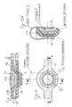
- FIG. 1 1 shows a first embodiment of a stop valve 2 formed on a catheter 1, which is formed directly on or in the catheter tube, preferably in the vicinity of the point of departure of the pump (not shown).
- the check valve 2 is designed such that it blocks at a hose internal pressure or pressure of the guided in the tube 1 medium of 0.1 bar or less and opens at higher pressures and allows flow through the flow area 1b of the catheter 1.
- the first embodiment of the catheter 1 shown can be obtained, for example, by means of a catheter or tube forming in the region of the valve 2 by means of a heat-forming method.
- the annular or tubular cross-section of the catheter 1 is thereby converted in the region of the valve 2 into a flat tube, as in the sectional view in FIG Figure 1A shown, so that the wall halves 1a of the catheter 1 abut each other and thus a Can prevent flow at a low applied internal pressure. If the pressure of the medium guided in the catheter 1 rises above the predetermined minimum pressure of, for example, 0.1 bar, the catheter inner wall 1c is pushed open and the valve 2 is opened so that a flow through the catheter 1 is possible.
- the valve 2 can be equipped with a clamp 3, which is designed as a U-shaped spring element, with An horrin 3a and 3b.
- the clamp 3 is arranged around the catheter 1 around and can bias the catheter halves and thus the catheter inner walls 1c against each other via their clamping force.
- a defined blocking force or a defined barrier pressure can be set. The greater the force with which the clamp 3 presses the catheter walls 1c together, the greater the minimum pressure of the medium which must be present in order to allow a flow through the catheter 1.
- a catheter 1 is provided with one or more e.g. Connected in the longitudinal direction of the catheter 1 in succession valves 2 to an administration device, such as z, B, an infusion pump, the catheter 1 is connected to a reservoir 4 for a substance to be administered or a medium.
- an administration device such as z, B, an infusion pump
- the catheter 1 is connected to a reservoir 4 for a substance to be administered or a medium.
- a stopper 5 is inserted from an infusion pump into the reservoir 4 or an ampoule 4, so that an increase in the internal pressure occurs in the ampoule 4 and a substance contained in the ampoule 4 is dispensed from a delivery opening 4a of the ampoule 4.
- Insulin can be delivered to a patient. Once the desired amount of the substance is administered and e.g. the plug 5 of the reservoir 4 is again at rest, the valve 2 closes by itself due to the force of the clamp 3, which compresses the catheter 1 again, About the biasing force of the clip 3, the opening pressure for the valve 2 is thus set or defined ,
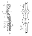
- FIG. 2 shows a second embodiment of a catheter 1 according to the invention with two valves 2.
- the two valves 2 are arranged in two spaced-apart in the longitudinal direction of the catheter 1 zones and each have mutually prestressed catheter walls 1a on. It is an in FIG. 2A
- the catheter wall 1a shown on the left is biased towards the second side (downwards) in such a way that the catheter inner walls 1a abut one another and prevent a flow of a medium, unless a predetermined minimum pressure is applied.
- the bias voltage is reversed relative to the first valve, that is, the opposite second side is biased toward the first side so that the desired valve locking effect occurs.
- Each bias of a catheter wall 1 a can be regarded as a diaphragm, in a series connection of multiple diaphragms, the total pressure difference is divided into step pressure differences, so that the pressure drop per valve zone can be reduced.
- a reduction of the total pressure difference is advantageous because it can reduce the closing force per valve zone and thus the reliability of the overall valve formed from a plurality of valve zones can be increased.
- a valve function with a catheter 1 can be achieved in that the catheter 1 is brought into a bending region with a defined travel force element (spring). With increasing pressure, e.g. between 0.5 and 0.8 bar, the catheter 1 frees itself from the kink area and thus releases the flow,
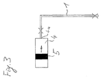
- FIG. 3 schematically shows an ampoule 4 with a displaceable therein in the arrow direction plug 5, with which a substance contained in the ampoule 4 can be discharged from a discharge opening 4a to the connected to the ampoule 4 catheter 1.
- the height difference between the lower and the upper end of the catheter for example, be one meter, so would be at the upper end of the catheter 1, a negative pressure of 0.1 bar, which could lead to inadvertently from the ampoule 4 solely due to the hydrostatic Pressure, which is generated by the liquid column in the catheter 1, a substance is discharged from the ampoule 4 uncontrolled.
- a valve in the upper catheter area, since a negative pressure of 0.1 bar with respect to a relative external pressure of 0 bar leads to an independent compression of the catheter walls 1a.
- the negative pressure in the upper catheter section can therefore be used in elastic catheter walls 1a such that in the case of a hydrostatic pressure distribution in the catheter, an automatic closure of the valve takes place.
- the catheter 1 according to the invention described above can be prevented that a substance is inadvertently released from the ampule 4 through the catheter 1.
- a plurality of bending regions 1d can also be arranged one behind the other, as in FIG FIG. 4 shown.
- a catheter or tube 1 is accommodated in a clamping piece or a clip 3, which may consist of a clamping piece upper part 3c and a clamping piece lower part 3d, which may be interconnected.
- the catheter 1 is inserted into the catheter guides formed eg by a plurality of preferably mutually parallel partitions 3e that the catheter 1, for example, tortuous or snake-shaped or wound in the clamping piece 3 is held, straight areas of the catheter 1 are parallel to each other through the wall pieces 3e separated, wherein in each case in the region of the transition of the catheter 1 from a guide formed by two adjacent wall sections 3e to the next guide a kink region 1d is present.
- FIG. 4 shows the state with open catheter 1, in which the buckling portions 1d are open due to an applied pressure of eg greater than 0.7 bar and thus allow a flow of a medium through the catheter 1 therethrough. If a pressure below 0.7 bar, so the catheter 1 is deformed in the region of the creases 1 d so that a passage of a medium through the catheter 1 is prevented.
- the clamping piece 3 may for example be rigid, so that results in a pressure increase of the guided in the catheter 1 medium to more than 0.7 bar solely by the deformation of the catheter 1, a flow possibility.
- the clamping piece 3 may also be elastic or resilient, so that the clamping piece 3 deforms or expands at a pressure increase of the guided in the catheter 1 medium and thus releases the flow for the sensed in the catheter 1 liquid.
- clamping piece 3 could in principle be formed in one piece, it is preferred for easier insertion of the catheter 1, that the clamping piece 3 of two sections 3 c and 3d is formed, which can be placed on each other or connected to each other, after the catheter 1 in the clamping piece 3 d in the FIG. 4 shown type has been inserted so that the catheter 1 has a plurality of successive kink areas 1d preferably on two opposite sides of the clamping piece 3.
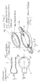
- FIG. 5A shows a further embodiment of a locking mechanism for a catheter 1
- a catheter-blocking valve can be integrated into both the catheter 1 and be integrated, as well as formed as a separate valve piece, which can be used between two catheter pieces 1.
- a valve base body 4 made of a thermoplastic elastomer (TBE) is shown, which disc-shaped or plate-shaped and preferably formed flat and was inserted between two catheter pieces 1, wherein the valve body 4 attached to the catheter pieces 1 in the region of a weld zone 4a and connected or welded to the catheter pieces 1 so as to be an integral part of the catheter.
- TBE thermoplastic elastomer
- a closure or cover 4b is placed in the form of a likewise molded from a thermoplastic elastomer film which may be double coated and formed of a different material than the valve body 4.
- the film 4b is connected to the valve Basic body 4 connected in the region of a weld zone 4c.
- FIG. 5C is a top view of the in FIG. 5B Clamp 3 shown in a side view.
- the foil 4b is thus pressed into the valve base 4 by the clamp 3 or compressed together with the foil 4b such that no flow of a medium can take place. If the pressure of the medium rises above 0.7 bar, the Clamp 3 pressed apart by the pressure of the medium, ie the pressure surfaces 3f and 3g are pushed away from each other to allow a flow of a medium.
- the barrier pressure of in FIG. 5 shown valve, so that the valve opens even at a lower pressure of eg 0.1 or 0.2 bar or at a higher pressure of eg 1 bar or above.
Landscapes
- Health & Medical Sciences (AREA)
- Heart & Thoracic Surgery (AREA)
- Life Sciences & Earth Sciences (AREA)
- Hematology (AREA)
- Anesthesiology (AREA)
- Biomedical Technology (AREA)
- Engineering & Computer Science (AREA)
- Pulmonology (AREA)
- Animal Behavior & Ethology (AREA)
- General Health & Medical Sciences (AREA)
- Public Health (AREA)
- Veterinary Medicine (AREA)
- Biophysics (AREA)
- Infusion, Injection, And Reservoir Apparatuses (AREA)
Priority Applications (6)
| Application Number | Priority Date | Filing Date | Title |
|---|---|---|---|
| AT07111423T ATE491492T1 (de) | 2007-06-29 | 2007-06-29 | Vorrichtung zur verhinderung eines freien katheterdurchflusses |
| EP07111423A EP2008681B1 (fr) | 2007-06-29 | 2007-06-29 | Dispositif pour éviter l'écoulement libre d'un liquide dans un cathéter |
| DE502007005954T DE502007005954D1 (de) | 2007-06-29 | 2007-06-29 | Vorrichtung zur Verhinderung eines freien Katheterdurchflusses |
| PCT/EP2008/004281 WO2009003560A1 (fr) | 2007-06-29 | 2008-05-29 | Dispositif pour empêcher l'écoulement libre d'un cathéter |
| US12/644,446 US8114056B2 (en) | 2007-06-29 | 2009-12-22 | Device for preventing a free catheter flow |
| US13/349,936 US8382720B2 (en) | 2007-06-29 | 2012-01-13 | Device for preventing a free catheter flow |
Applications Claiming Priority (1)
| Application Number | Priority Date | Filing Date | Title |
|---|---|---|---|
| EP07111423A EP2008681B1 (fr) | 2007-06-29 | 2007-06-29 | Dispositif pour éviter l'écoulement libre d'un liquide dans un cathéter |
Publications (2)
| Publication Number | Publication Date |
|---|---|
| EP2008681A1 true EP2008681A1 (fr) | 2008-12-31 |
| EP2008681B1 EP2008681B1 (fr) | 2010-12-15 |
Family
ID=38626728
Family Applications (1)
| Application Number | Title | Priority Date | Filing Date |
|---|---|---|---|
| EP07111423A Active EP2008681B1 (fr) | 2007-06-29 | 2007-06-29 | Dispositif pour éviter l'écoulement libre d'un liquide dans un cathéter |
Country Status (5)
| Country | Link |
|---|---|
| US (2) | US8114056B2 (fr) |
| EP (1) | EP2008681B1 (fr) |
| AT (1) | ATE491492T1 (fr) |
| DE (1) | DE502007005954D1 (fr) |
| WO (1) | WO2009003560A1 (fr) |
Cited By (1)
| Publication number | Priority date | Publication date | Assignee | Title |
|---|---|---|---|---|
| WO2012019726A1 (fr) | 2010-08-07 | 2012-02-16 | Roche Diagnostics Gmbh | Valve pour système de perfusion ambulatoire, et système de perfusion ambulatoire comportant une valve |
Families Citing this family (7)
| Publication number | Priority date | Publication date | Assignee | Title |
|---|---|---|---|---|
| EP2238998A1 (fr) | 2009-04-02 | 2010-10-13 | F. Hoffmann-La Roche AG | Canule pour percer le septum d'une cartouche et valvule pour la canule |
| US8926561B2 (en) | 2009-07-30 | 2015-01-06 | Tandem Diabetes Care, Inc. | Infusion pump system with disposable cartridge having pressure venting and pressure feedback |
| US9180242B2 (en) | 2012-05-17 | 2015-11-10 | Tandem Diabetes Care, Inc. | Methods and devices for multiple fluid transfer |
| US9173998B2 (en) | 2013-03-14 | 2015-11-03 | Tandem Diabetes Care, Inc. | System and method for detecting occlusions in an infusion pump |
| US20170120039A1 (en) * | 2015-11-04 | 2017-05-04 | Depuy Mitek, Llc | Anti-Clogging Fluid Management System |
| US11213460B2 (en) | 2018-09-19 | 2022-01-04 | Vesco Medical Llc | Connectors for infusion pump feeding sets |
| KR102869870B1 (ko) * | 2023-06-12 | 2025-10-16 | 주식회사 진우기술개발 | 과열 방지가 가능한 휴대용 가스버너 |
Citations (10)
| Publication number | Priority date | Publication date | Assignee | Title |
|---|---|---|---|---|
| DE36527C (de) | J. RIEDEL in Berlin N., Borsigstr. 24 | Quetschverschlufs für Schläuche durch Umknicken derselben | ||
| US939324A (en) | 1909-05-29 | 1909-11-09 | William C Robinson | Metal-punch. |
| US3103335A (en) | 1961-03-28 | 1963-09-10 | Resiflex Lab Inc | Unitary clamp means for flexible tubes |
| US4453696A (en) | 1978-12-06 | 1984-06-12 | Witt John E | Device for attachment of a resilient and/or flexible tube onto a nipple, nozzle or like connection |
| US4515589A (en) | 1981-03-23 | 1985-05-07 | Austin Jon W | Peristaltic pumping method and apparatus |
| EP0273714A2 (fr) | 1986-12-31 | 1988-07-06 | Minnesota Mining And Manufacturing Company | Ensemble de pompe péristaltique |
| US5232193A (en) | 1989-09-20 | 1993-08-03 | Baxter International Inc. | Clamp for intravenous tubing |
| US6454742B1 (en) | 2000-03-01 | 2002-09-24 | Sherwood Services, Ag | Valve cuff for a fluid administration system |
| US20040087911A1 (en) * | 2002-10-31 | 2004-05-06 | Feliciano Ari J. | Quick flow control for flexible tubing |
| EP1466646A1 (fr) | 2003-04-10 | 2004-10-13 | Nutricia Healthcare S.A. | Dispositif de sécurité contre l'écoulement libre |
Family Cites Families (11)
| Publication number | Priority date | Publication date | Assignee | Title |
|---|---|---|---|---|
| FR78023E (fr) * | 1960-07-04 | 1962-05-26 | Bruneau & Cie Lab | Dispositif de réglage de débit dans un tube déformable |
| US5186431A (en) * | 1989-09-22 | 1993-02-16 | Yehuda Tamari | Pressure sensitive valves for extracorporeal circuits |
| US6039078A (en) * | 1989-09-22 | 2000-03-21 | Tamari; Yehuda | Inline extracorporeal reservoir and pressure isolator |
| US5814004A (en) * | 1989-09-22 | 1998-09-29 | Tamari; Yehuda | System for regulating pressure within an extracorporeal circuit |
| US5250034A (en) * | 1990-09-17 | 1993-10-05 | E-Z-Em, Inc. | Pressure responsive valve catheter |
| DE59304812D1 (de) * | 1992-06-02 | 1997-01-30 | Profiform Ag | Selbstschliessendes katheterventil |
| DE69432107T2 (de) | 1993-12-13 | 2003-10-23 | Migada Inc., Englewood Cliffs | Medizinische infusionsvorrichtung mit sicherheitsventil |
| US5396925A (en) * | 1993-12-16 | 1995-03-14 | Abbott Laboratories | Anti-free flow valve, enabling fluid flow as a function of pressure and selectively opened to enable free flow |
| ATE188132T1 (de) | 1995-07-06 | 2000-01-15 | Disetronic Licensing Ag | Einweg-kassette zum anschliessen an eine infusionspumpe für ein flüssiges arzneimittel |
| DE19723648C1 (de) | 1997-06-05 | 1998-08-27 | Disetronic Licensing Ag | Vorrichtung zur dosierten Verabreichung einer Medikamentflüssigkeit |
| EP1009944A4 (fr) * | 1997-07-03 | 2004-06-30 | Prec Dispensing Systems Ltd | Mecanisme de pincement de tube souple |
-
2007
- 2007-06-29 DE DE502007005954T patent/DE502007005954D1/de active Active
- 2007-06-29 EP EP07111423A patent/EP2008681B1/fr active Active
- 2007-06-29 AT AT07111423T patent/ATE491492T1/de active
-
2008
- 2008-05-29 WO PCT/EP2008/004281 patent/WO2009003560A1/fr not_active Ceased
-
2009
- 2009-12-22 US US12/644,446 patent/US8114056B2/en active Active
-
2012
- 2012-01-13 US US13/349,936 patent/US8382720B2/en active Active
Patent Citations (10)
| Publication number | Priority date | Publication date | Assignee | Title |
|---|---|---|---|---|
| DE36527C (de) | J. RIEDEL in Berlin N., Borsigstr. 24 | Quetschverschlufs für Schläuche durch Umknicken derselben | ||
| US939324A (en) | 1909-05-29 | 1909-11-09 | William C Robinson | Metal-punch. |
| US3103335A (en) | 1961-03-28 | 1963-09-10 | Resiflex Lab Inc | Unitary clamp means for flexible tubes |
| US4453696A (en) | 1978-12-06 | 1984-06-12 | Witt John E | Device for attachment of a resilient and/or flexible tube onto a nipple, nozzle or like connection |
| US4515589A (en) | 1981-03-23 | 1985-05-07 | Austin Jon W | Peristaltic pumping method and apparatus |
| EP0273714A2 (fr) | 1986-12-31 | 1988-07-06 | Minnesota Mining And Manufacturing Company | Ensemble de pompe péristaltique |
| US5232193A (en) | 1989-09-20 | 1993-08-03 | Baxter International Inc. | Clamp for intravenous tubing |
| US6454742B1 (en) | 2000-03-01 | 2002-09-24 | Sherwood Services, Ag | Valve cuff for a fluid administration system |
| US20040087911A1 (en) * | 2002-10-31 | 2004-05-06 | Feliciano Ari J. | Quick flow control for flexible tubing |
| EP1466646A1 (fr) | 2003-04-10 | 2004-10-13 | Nutricia Healthcare S.A. | Dispositif de sécurité contre l'écoulement libre |
Cited By (1)
| Publication number | Priority date | Publication date | Assignee | Title |
|---|---|---|---|---|
| WO2012019726A1 (fr) | 2010-08-07 | 2012-02-16 | Roche Diagnostics Gmbh | Valve pour système de perfusion ambulatoire, et système de perfusion ambulatoire comportant une valve |
Also Published As
| Publication number | Publication date |
|---|---|
| WO2009003560A1 (fr) | 2009-01-08 |
| US20120179116A1 (en) | 2012-07-12 |
| US8382720B2 (en) | 2013-02-26 |
| US8114056B2 (en) | 2012-02-14 |
| DE502007005954D1 (de) | 2011-01-27 |
| US20100185151A1 (en) | 2010-07-22 |
| ATE491492T1 (de) | 2011-01-15 |
| EP2008681B1 (fr) | 2010-12-15 |
Similar Documents
| Publication | Publication Date | Title |
|---|---|---|
| DE19723648C1 (de) | Vorrichtung zur dosierten Verabreichung einer Medikamentflüssigkeit | |
| DE3390255C3 (de) | Infusions-Vorrichtung | |
| DE69323739T2 (de) | Arzneimittel infusionsvorrichtung | |
| DE3915251C2 (fr) | ||
| EP2008681B1 (fr) | Dispositif pour éviter l'écoulement libre d'un liquide dans un cathéter | |
| DE69409587T2 (de) | Verfahren zum Spülen eines Katheters und Katheter | |
| EP0412191B1 (fr) | Dispositif de perfusion implantable | |
| DE69328271T2 (de) | Flüssigkeitssteuervorrichtung mit automatischen Ventil | |
| DE102009060533B4 (de) | Implantierbares Shuntsystem | |
| DE2906076A1 (de) | Verfahren und vorrichtung zur dosierten abgabe einer fluessigkeit | |
| DE2123131A1 (de) | Klemme für flexible Rohre, insbesondere Rohre von Infusionsbestecken und Verfahren zur Steuerung des Stromes in derartigen Rohren | |
| EP0233986B1 (fr) | Cathéter intrapéritonéal pour l'administration de médicaments liquides, en particulier de l'insuline | |
| CH699723B1 (de) | Vorrichtung zur Verabreichung eines fluiden Produkts. | |
| EP3088019B1 (fr) | Dispositif destine a transmettre un fluide | |
| DE602004003168T2 (de) | Impantierbares Gerät zur Verabreichung von Medikamenten mit einer Kapillaröffnung für geringe Durchflussraten | |
| DE2654655A1 (de) | Infusionsvorrichtung | |
| DE4436540A1 (de) | Infusionssystem zur kontinuierlichen Abgabe eines flüssigen Medikaments unter Druck | |
| DE69805888T2 (de) | Vorrichtung zur Selbstverabreichung flüssiger Medikamente | |
| DE69910323T2 (de) | Flüssigkeitsabgabevorrichtung | |
| DE2942801A1 (de) | Regler fuer eine fluessigkeits-dosiervorrichtung | |
| DE69408765T2 (de) | Infusionsvorrichtung | |
| DE602004000626T2 (de) | Medizinische Abgabevorrichtung für Fluide mit niedriger Fluiddurchflussrate | |
| CH660973A5 (de) | Infusionseinrichtung. | |
| DE2509485A1 (de) | Mehrwegeventil fuer mit schlaeuchen ausgeruestete medizinischen geraete, chemische geraete o.dgl. | |
| EP3325045A1 (fr) | Dispositif d'actionnement pour l'administration d'un bolus |
Legal Events
| Date | Code | Title | Description |
|---|---|---|---|
| PUAI | Public reference made under article 153(3) epc to a published international application that has entered the european phase |
Free format text: ORIGINAL CODE: 0009012 |
|
| AK | Designated contracting states |
Kind code of ref document: A1 Designated state(s): AT BE BG CH CY CZ DE DK EE ES FI FR GB GR HU IE IS IT LI LT LU LV MC MT NL PL PT RO SE SI SK TR |
|
| AX | Request for extension of the european patent |
Extension state: AL BA HR MK RS |
|
| 17P | Request for examination filed |
Effective date: 20090630 |
|
| RAP1 | Party data changed (applicant data changed or rights of an application transferred) |
Owner name: F.HOFFMANN-LA ROCHE AG Owner name: ROCHE DIAGNOSTICS GMBH |
|
| 17Q | First examination report despatched |
Effective date: 20090731 |
|
| AKX | Designation fees paid |
Designated state(s): AT BE BG CH CY CZ DE DK EE ES FI FR GB GR HU IE IS IT LI LT LU LV MC MT NL PL PT RO SE SI SK TR |
|
| GRAP | Despatch of communication of intention to grant a patent |
Free format text: ORIGINAL CODE: EPIDOSNIGR1 |
|
| GRAS | Grant fee paid |
Free format text: ORIGINAL CODE: EPIDOSNIGR3 |
|
| GRAA | (expected) grant |
Free format text: ORIGINAL CODE: 0009210 |
|
| AK | Designated contracting states |
Kind code of ref document: B1 Designated state(s): AT BE BG CH CY CZ DE DK EE ES FI FR GB GR HU IE IS IT LI LT LU LV MC MT NL PL PT RO SE SI SK TR |
|
| REG | Reference to a national code |
Ref country code: CH Ref legal event code: EP Ref country code: GB Ref legal event code: FG4D Free format text: NOT ENGLISH |
|
| REG | Reference to a national code |
Ref country code: CH Ref legal event code: NV Representative=s name: RIEDERER HASLER & PARTNER PATENTANWAELTE AG |
|
| REG | Reference to a national code |
Ref country code: IE Ref legal event code: FG4D |
|
| REF | Corresponds to: |
Ref document number: 502007005954 Country of ref document: DE Date of ref document: 20110127 Kind code of ref document: P |
|
| REG | Reference to a national code |
Ref country code: NL Ref legal event code: VDEP Effective date: 20101215 |
|
| PG25 | Lapsed in a contracting state [announced via postgrant information from national office to epo] |
Ref country code: LT Free format text: LAPSE BECAUSE OF FAILURE TO SUBMIT A TRANSLATION OF THE DESCRIPTION OR TO PAY THE FEE WITHIN THE PRESCRIBED TIME-LIMIT Effective date: 20101215 |
|
| LTIE | Lt: invalidation of european patent or patent extension |
Effective date: 20101215 |
|
| PG25 | Lapsed in a contracting state [announced via postgrant information from national office to epo] |
Ref country code: BG Free format text: LAPSE BECAUSE OF FAILURE TO SUBMIT A TRANSLATION OF THE DESCRIPTION OR TO PAY THE FEE WITHIN THE PRESCRIBED TIME-LIMIT Effective date: 20110315 Ref country code: SE Free format text: LAPSE BECAUSE OF FAILURE TO SUBMIT A TRANSLATION OF THE DESCRIPTION OR TO PAY THE FEE WITHIN THE PRESCRIBED TIME-LIMIT Effective date: 20101215 Ref country code: CY Free format text: LAPSE BECAUSE OF FAILURE TO SUBMIT A TRANSLATION OF THE DESCRIPTION OR TO PAY THE FEE WITHIN THE PRESCRIBED TIME-LIMIT Effective date: 20101215 Ref country code: SI Free format text: LAPSE BECAUSE OF FAILURE TO SUBMIT A TRANSLATION OF THE DESCRIPTION OR TO PAY THE FEE WITHIN THE PRESCRIBED TIME-LIMIT Effective date: 20101215 Ref country code: LV Free format text: LAPSE BECAUSE OF FAILURE TO SUBMIT A TRANSLATION OF THE DESCRIPTION OR TO PAY THE FEE WITHIN THE PRESCRIBED TIME-LIMIT Effective date: 20101215 Ref country code: FI Free format text: LAPSE BECAUSE OF FAILURE TO SUBMIT A TRANSLATION OF THE DESCRIPTION OR TO PAY THE FEE WITHIN THE PRESCRIBED TIME-LIMIT Effective date: 20101215 Ref country code: NL Free format text: LAPSE BECAUSE OF FAILURE TO SUBMIT A TRANSLATION OF THE DESCRIPTION OR TO PAY THE FEE WITHIN THE PRESCRIBED TIME-LIMIT Effective date: 20101215 |
|
| REG | Reference to a national code |
Ref country code: IE Ref legal event code: FD4D |
|
| PG25 | Lapsed in a contracting state [announced via postgrant information from national office to epo] |
Ref country code: GR Free format text: LAPSE BECAUSE OF FAILURE TO SUBMIT A TRANSLATION OF THE DESCRIPTION OR TO PAY THE FEE WITHIN THE PRESCRIBED TIME-LIMIT Effective date: 20110316 Ref country code: PT Free format text: LAPSE BECAUSE OF FAILURE TO SUBMIT A TRANSLATION OF THE DESCRIPTION OR TO PAY THE FEE WITHIN THE PRESCRIBED TIME-LIMIT Effective date: 20110415 Ref country code: CZ Free format text: LAPSE BECAUSE OF FAILURE TO SUBMIT A TRANSLATION OF THE DESCRIPTION OR TO PAY THE FEE WITHIN THE PRESCRIBED TIME-LIMIT Effective date: 20101215 Ref country code: EE Free format text: LAPSE BECAUSE OF FAILURE TO SUBMIT A TRANSLATION OF THE DESCRIPTION OR TO PAY THE FEE WITHIN THE PRESCRIBED TIME-LIMIT Effective date: 20101215 Ref country code: IE Free format text: LAPSE BECAUSE OF FAILURE TO SUBMIT A TRANSLATION OF THE DESCRIPTION OR TO PAY THE FEE WITHIN THE PRESCRIBED TIME-LIMIT Effective date: 20101215 Ref country code: IS Free format text: LAPSE BECAUSE OF FAILURE TO SUBMIT A TRANSLATION OF THE DESCRIPTION OR TO PAY THE FEE WITHIN THE PRESCRIBED TIME-LIMIT Effective date: 20110415 Ref country code: ES Free format text: LAPSE BECAUSE OF FAILURE TO SUBMIT A TRANSLATION OF THE DESCRIPTION OR TO PAY THE FEE WITHIN THE PRESCRIBED TIME-LIMIT Effective date: 20110326 |
|
| PG25 | Lapsed in a contracting state [announced via postgrant information from national office to epo] |
Ref country code: PL Free format text: LAPSE BECAUSE OF FAILURE TO SUBMIT A TRANSLATION OF THE DESCRIPTION OR TO PAY THE FEE WITHIN THE PRESCRIBED TIME-LIMIT Effective date: 20101215 Ref country code: SK Free format text: LAPSE BECAUSE OF FAILURE TO SUBMIT A TRANSLATION OF THE DESCRIPTION OR TO PAY THE FEE WITHIN THE PRESCRIBED TIME-LIMIT Effective date: 20101215 Ref country code: RO Free format text: LAPSE BECAUSE OF FAILURE TO SUBMIT A TRANSLATION OF THE DESCRIPTION OR TO PAY THE FEE WITHIN THE PRESCRIBED TIME-LIMIT Effective date: 20101215 |
|
| PLBE | No opposition filed within time limit |
Free format text: ORIGINAL CODE: 0009261 |
|
| STAA | Information on the status of an ep patent application or granted ep patent |
Free format text: STATUS: NO OPPOSITION FILED WITHIN TIME LIMIT |
|
| PG25 | Lapsed in a contracting state [announced via postgrant information from national office to epo] |
Ref country code: DK Free format text: LAPSE BECAUSE OF FAILURE TO SUBMIT A TRANSLATION OF THE DESCRIPTION OR TO PAY THE FEE WITHIN THE PRESCRIBED TIME-LIMIT Effective date: 20101215 |
|
| 26N | No opposition filed |
Effective date: 20110916 |
|
| PG25 | Lapsed in a contracting state [announced via postgrant information from national office to epo] |
Ref country code: MT Free format text: LAPSE BECAUSE OF FAILURE TO SUBMIT A TRANSLATION OF THE DESCRIPTION OR TO PAY THE FEE WITHIN THE PRESCRIBED TIME-LIMIT Effective date: 20101215 Ref country code: IT Free format text: LAPSE BECAUSE OF FAILURE TO SUBMIT A TRANSLATION OF THE DESCRIPTION OR TO PAY THE FEE WITHIN THE PRESCRIBED TIME-LIMIT Effective date: 20101215 |
|
| BERE | Be: lapsed |
Owner name: ROCHE DIAGNOSTICS G.M.B.H. Effective date: 20110630 Owner name: F.HOFFMANN-LA ROCHE A.G. Effective date: 20110630 |
|
| REG | Reference to a national code |
Ref country code: DE Ref legal event code: R097 Ref document number: 502007005954 Country of ref document: DE Effective date: 20110916 |
|
| GBPC | Gb: european patent ceased through non-payment of renewal fee |
Effective date: 20110629 |
|
| PG25 | Lapsed in a contracting state [announced via postgrant information from national office to epo] |
Ref country code: BE Free format text: LAPSE BECAUSE OF NON-PAYMENT OF DUE FEES Effective date: 20110630 |
|
| PG25 | Lapsed in a contracting state [announced via postgrant information from national office to epo] |
Ref country code: GB Free format text: LAPSE BECAUSE OF NON-PAYMENT OF DUE FEES Effective date: 20110629 |
|
| PG25 | Lapsed in a contracting state [announced via postgrant information from national office to epo] |
Ref country code: MC Free format text: LAPSE BECAUSE OF NON-PAYMENT OF DUE FEES Effective date: 20110630 |
|
| PG25 | Lapsed in a contracting state [announced via postgrant information from national office to epo] |
Ref country code: LU Free format text: LAPSE BECAUSE OF NON-PAYMENT OF DUE FEES Effective date: 20110629 |
|
| REG | Reference to a national code |
Ref country code: AT Ref legal event code: MM01 Ref document number: 491492 Country of ref document: AT Kind code of ref document: T Effective date: 20120629 |
|
| PG25 | Lapsed in a contracting state [announced via postgrant information from national office to epo] |
Ref country code: TR Free format text: LAPSE BECAUSE OF FAILURE TO SUBMIT A TRANSLATION OF THE DESCRIPTION OR TO PAY THE FEE WITHIN THE PRESCRIBED TIME-LIMIT Effective date: 20101215 |
|
| PG25 | Lapsed in a contracting state [announced via postgrant information from national office to epo] |
Ref country code: AT Free format text: LAPSE BECAUSE OF NON-PAYMENT OF DUE FEES Effective date: 20120629 Ref country code: HU Free format text: LAPSE BECAUSE OF FAILURE TO SUBMIT A TRANSLATION OF THE DESCRIPTION OR TO PAY THE FEE WITHIN THE PRESCRIBED TIME-LIMIT Effective date: 20101215 |
|
| REG | Reference to a national code |
Ref country code: FR Ref legal event code: PLFP Year of fee payment: 10 |
|
| REG | Reference to a national code |
Ref country code: FR Ref legal event code: PLFP Year of fee payment: 11 |
|
| REG | Reference to a national code |
Ref country code: FR Ref legal event code: PLFP Year of fee payment: 12 |
|
| REG | Reference to a national code |
Ref country code: DE Ref legal event code: R082 Ref document number: 502007005954 Country of ref document: DE Ref country code: DE Ref legal event code: R081 Ref document number: 502007005954 Country of ref document: DE Owner name: ROCHE DIABETES CARE GMBH, DE Free format text: FORMER OWNER: ROCHE DIAGNOSTICS GMBH, 82377 PENZBERG, DE |
|
| PGFP | Annual fee paid to national office [announced via postgrant information from national office to epo] |
Ref country code: DE Payment date: 20240521 Year of fee payment: 18 |
|
| PGFP | Annual fee paid to national office [announced via postgrant information from national office to epo] |
Ref country code: FR Payment date: 20240522 Year of fee payment: 18 |
|
| PGFP | Annual fee paid to national office [announced via postgrant information from national office to epo] |
Ref country code: CH Payment date: 20240701 Year of fee payment: 18 |
|
| REG | Reference to a national code |
Ref country code: DE Ref legal event code: R119 Ref document number: 502007005954 Country of ref document: DE |
|
| REG | Reference to a national code |
Ref country code: CH Ref legal event code: H13 Free format text: ST27 STATUS EVENT CODE: U-0-0-H10-H13 (AS PROVIDED BY THE NATIONAL OFFICE) Effective date: 20260127 |
|
| PG25 | Lapsed in a contracting state [announced via postgrant information from national office to epo] |
Ref country code: DE Free format text: LAPSE BECAUSE OF NON-PAYMENT OF DUE FEES Effective date: 20260101 |
|
| PG25 | Lapsed in a contracting state [announced via postgrant information from national office to epo] |
Ref country code: FR Free format text: LAPSE BECAUSE OF NON-PAYMENT OF DUE FEES Effective date: 20250630 |
|
| PG25 | Lapsed in a contracting state [announced via postgrant information from national office to epo] |
Ref country code: CH Free format text: LAPSE BECAUSE OF NON-PAYMENT OF DUE FEES Effective date: 20250630 |