EP2008687B1 - Werkzeug zur befestigung eines transkranialen magnetischen stimulationskopfes und transkranialer magnetischer stimulator - Google Patents
Werkzeug zur befestigung eines transkranialen magnetischen stimulationskopfes und transkranialer magnetischer stimulator Download PDFInfo
- Publication number
- EP2008687B1 EP2008687B1 EP07741847.3A EP07741847A EP2008687B1 EP 2008687 B1 EP2008687 B1 EP 2008687B1 EP 07741847 A EP07741847 A EP 07741847A EP 2008687 B1 EP2008687 B1 EP 2008687B1
- Authority
- EP
- European Patent Office
- Prior art keywords
- magnetic field
- head
- generating means
- field generating
- examinee
- Prior art date
- Legal status (The legal status is an assumption and is not a legal conclusion. Google has not performed a legal analysis and makes no representation as to the accuracy of the status listed.)
- Active
Links
Images





Classifications
-
- A—HUMAN NECESSITIES
- A61—MEDICAL OR VETERINARY SCIENCE; HYGIENE
- A61N—ELECTROTHERAPY; MAGNETOTHERAPY; RADIATION THERAPY; ULTRASOUND THERAPY
- A61N2/00—Magnetotherapy
- A61N2/02—Magnetotherapy using magnetic fields produced by coils, including single turn loops or electromagnets
-
- A—HUMAN NECESSITIES
- A61—MEDICAL OR VETERINARY SCIENCE; HYGIENE
- A61B—DIAGNOSIS; SURGERY; IDENTIFICATION
- A61B34/00—Computer-aided surgery; Manipulators or robots specially adapted for use in surgery
- A61B34/20—Surgical navigation systems; Devices for tracking or guiding surgical instruments, e.g. for frameless stereotaxis
-
- A—HUMAN NECESSITIES
- A61—MEDICAL OR VETERINARY SCIENCE; HYGIENE
- A61B—DIAGNOSIS; SURGERY; IDENTIFICATION
- A61B90/00—Instruments, implements or accessories specially adapted for surgery or diagnosis and not covered by any of the groups A61B1/00 - A61B50/00, e.g. for luxation treatment or for protecting wound edges
- A61B90/10—Instruments, implements or accessories specially adapted for surgery or diagnosis and not covered by any of the groups A61B1/00 - A61B50/00, e.g. for luxation treatment or for protecting wound edges for stereotaxic surgery, e.g. frame-based stereotaxis
- A61B90/14—Fixators for body parts, e.g. skull clamps; Constructional details of fixators, e.g. pins
-
- A—HUMAN NECESSITIES
- A61—MEDICAL OR VETERINARY SCIENCE; HYGIENE
- A61N—ELECTROTHERAPY; MAGNETOTHERAPY; RADIATION THERAPY; ULTRASOUND THERAPY
- A61N2/00—Magnetotherapy
- A61N2/004—Magnetotherapy specially adapted for a specific therapy
- A61N2/006—Magnetotherapy specially adapted for a specific therapy for magnetic stimulation of nerve tissue
-
- A—HUMAN NECESSITIES
- A61—MEDICAL OR VETERINARY SCIENCE; HYGIENE
- A61B—DIAGNOSIS; SURGERY; IDENTIFICATION
- A61B34/00—Computer-aided surgery; Manipulators or robots specially adapted for use in surgery
- A61B34/10—Computer-aided planning, simulation or modelling of surgical operations
- A61B2034/107—Visualisation of planned trajectories or target regions
-
- A—HUMAN NECESSITIES
- A61—MEDICAL OR VETERINARY SCIENCE; HYGIENE
- A61B—DIAGNOSIS; SURGERY; IDENTIFICATION
- A61B34/00—Computer-aided surgery; Manipulators or robots specially adapted for use in surgery
- A61B34/20—Surgical navigation systems; Devices for tracking or guiding surgical instruments, e.g. for frameless stereotaxis
- A61B2034/2046—Tracking techniques
- A61B2034/2055—Optical tracking systems
-
- A—HUMAN NECESSITIES
- A61—MEDICAL OR VETERINARY SCIENCE; HYGIENE
- A61B—DIAGNOSIS; SURGERY; IDENTIFICATION
- A61B90/00—Instruments, implements or accessories specially adapted for surgery or diagnosis and not covered by any of the groups A61B1/00 - A61B50/00, e.g. for luxation treatment or for protecting wound edges
- A61B90/36—Image-producing devices or illumination devices not otherwise provided for
- A61B2090/364—Correlation of different images or relation of image positions in respect to the body
-
- Y—GENERAL TAGGING OF NEW TECHNOLOGICAL DEVELOPMENTS; GENERAL TAGGING OF CROSS-SECTIONAL TECHNOLOGIES SPANNING OVER SEVERAL SECTIONS OF THE IPC; TECHNICAL SUBJECTS COVERED BY FORMER USPC CROSS-REFERENCE ART COLLECTIONS [XRACs] AND DIGESTS
- Y10—TECHNICAL SUBJECTS COVERED BY FORMER USPC
- Y10T—TECHNICAL SUBJECTS COVERED BY FORMER US CLASSIFICATION
- Y10T29/00—Metal working
- Y10T29/49—Method of mechanical manufacture
- Y10T29/49002—Electrical device making
- Y10T29/4902—Electromagnet, transformer or inductor
Definitions
- the present invention relates to a repetitive transcranial magnetic stimulator, which reduce deafferentation pain (a neuropathic pain) due to a repetitive transcranial magnetic stimulation.
- a pain reduction effect against deafferentation pain which is identical with an electric stimulation
- a repetitive transcranial magnetic stimulation to stimulate a brain cortex neuron
- the repetitive transcranial magnetic stimulation is a method to generate a weak magnetic field and electric currents in a brain cortex neuron using a principle of an electromagnetic induction by instantaneously passing a current through a coil (see Fig. 6 ) and stimulate the brain cortex neuron noninvasively.
- Fig. 9 shows a conventional transcranial magnetic stimulator for carrying out a repetitive transcranial magnetic stimulation.
- the conventional transcranial magnetic stimulator is schematically configured by a magnetic stimulation control device 10', magnetic field generating means 8' including a coil, and a cable 7' to connect them.
- the magnetic stimulation control device 10' generates an electric current pulse of a relatively high frequency (for example, 5Hz to 20Hz) continuously or intermittently.
- the magnetic field generating means 8' includes a coil, through which electric current pulse from the magnetic stimulation control device 10' passes, therewithin. A magnetic field to be generated by this coil is applied from the outside of a cranium of an examinee to the brain cortex neuron so as to stimulate the brain cortex neuron.
- the conventional apparatus has a large scale, and extremely wide space and extremely large facilities are needed in order to carry out a magnetic stimulation treatment using the conventional apparatus. Further, it is very difficult to add magnetism to the spot-like target (the position, the direction, and the angle) of the brain cortex.
- an object of the present invention provides a repetitive transcranial magnetic stimulator, which can effectively carry out a transcranial magnetic stimulation, and this transcranial magnetic stimulator is simplified and minimized so that an examinee can carry out the transcranial magnetic stimulation at a clinic or at home continuously and repeatedly on a daily basis.
- the present invention has been made to attain the above-described object. It is defined by a method for manufacturing fixture of a head according to claim 1 and a kit of parts according to claim 2.
- transcranial magnetic stimulator according to the present invention is defined by the features of claim 7.
- the fixture of the head for a transcranial magnetic stimulation and the transcranial magnetic stimulator according to the present invention it is possible to carry out the transcranial magnetic stimulation repeatedly and continuously on a daily basis.
- a direction of the magnetic field generating means is a direction of magnetic field generating mean (a coil) on a surface of a head of an examinee
- an angle of the magnetic field generating mean is an angle made by a normal line of the surface of the head of the examinee and a direction of a magnetic field.
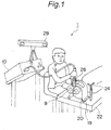
- Fig. 1 is a schematic view of a repetitive transcranial magnetic stimulator according to a first embodiment of the present invention, of which entire is represented by 1.
- a transcranial magnetic stimulator 1 according to the first embodiment includes a transcranial magnetic stimulation control device 10, magnetic field generating means 8 including a coil, and a cable to connect them.
- the transcranial magnetic stimulator 1 according to the first embodiment includes an optical navigation guide system.
- the optical navigation guide system includes a computer 21 shown in Fig. 3 , optical position grasping means 28 that is connected to the computer 21, first position displaying means 24 that is fixed on a treatment bed 22, and second position displaying means 26 that is attached to the magnetic field generating means 8.
- An operator who uses the transcranial magnetic stimulator 1 according to the first embodiment can stimulate a brain cortex while confirming a target based on an MRI (magnetic resonance imaging) image of the brain cortex of an examinee to be displayed on the display of the computer 21 and monitoring the position of the coil and the direction and the angle with respect to the surface of the brain in real time.
- the display of the MRI image of the brain cortex of the examinee and the display of the relative position of the coil (the magnetic field generating means) with respect to the brain cortex are carried out by the optical navigation guide system.
- the optical navigation guide system shown in Fig. 1 is based on a Brainsight Frameless Navigation system (registered trade mark) (Rogue Research Inc, Motreal, Canada).
- this mesh-like shell 20 is a mesh-like shell made of a thermoplastic resin to be used for a stereotactic radio surgery.
- the mesh-like shell 20 can save the shape of the head by its thermal plasticity.
- the position of a marker attached to the head of the examinee and the position of the first position displaying means 24 to be fixed on the treatment bed 22 are grasped by the computer 21 via the optical position grasping means 28 (to be described later) . Further, the position data of a marker that is attached to the head of the examinee and the marker data on the MRI three-dimensional image are connected by the computer 21.
- the computer 21 is capable of grasping the MRI image, the position of the head (the brain) of the examinee, and the position of the treatment bed 22 by connecting them.
- the relative position of the magnetic field generating means 8 to be used with respect to the head of the examinee can be grasped by the computer 21.
- the optical position grasping means 28 continuously grasps the position of the first position displaying means 24 to be fixed on the treatment bed 22 and the position of the second position displaying means 26 to be attached to the magnetic field generating means 8.
- the optical position grasping means 28 provides the first position information of the first position displaying means 24 and the second position information of the second position displaying means 26 to the computer 21, to which the optical position grasping means 28 is connected.
- the computer 21 grasps the relative position information of the above-described brain (the head) of the examinee with respect to the treatment bed 22, the position, the direction, and the angle of the magnetic field generating means 8 with respect to the brain cortex of the examinee can be calculated in real time to be displayed according to this relative position information, the above-described first position information, and the above-described second position information.
- the computer 21 displays the MRI image of the brain cortex, and the position, the direction, and the angle of the magnetic field generating means 8.
- an arrow 23 represents the positions, the directions, and the angles of the magnetic field generating means 8 and the generated magnetic field.
- the head is fixed to a fixed position of the treatment bed 22, which is inherent to the examinee, and then, an electric current pulse generated by the cranial magnetic stimulation control device 10 is continuously passed through the coil within the magnetic field generating means 8.
- the operator stimulates the appropriate position of the brain cortex while confirming the MRI image of the examinee on the display 25 of the computer 21 and the information of the magnetic field generating means.
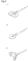
- Fig. 2 is a perspective view of the magnetic field generating means (coil) 8 to be used for a repetitive transcranial magnetic stimulator.
- the magnetic field generating means shown in Fig. 2(2) includes a circular coil.
- the magnetic field generating means in this case is easily fixed and is suitable for exercising stimulation in a wide range.
- the magnetic field generating means shown in Fig. 2(1) is configured by aligning two circular coils in a figure of eight on the same plane, and an electric current passes through two coils in a reverse direction.
- the magnetic field generating means shaped in a figure of eight has the highest density of an inductance electric current just below a point that is equivalent to a cross point of a figure of eight, and this magnetic field generating means is suitable for exercising localized stimulation although it is difficult to fix.
- the magnetic field generating means shown in Fig. 2(3) is configured by arranging two coils across a predetermined angle to be formed in a mountain shape (for example, a shape referred to as a double corn shape). It is preferable that any magnetic field generating means 8 shown in Figs. 2(1), 2(2), and 2(3) is molded by a resin.
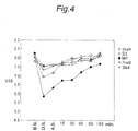
- Fig. 4 is a graph for showing a transition of the average values of a VAS (Visual Analogue Scale) before stimulation, during stimulation, just after stimulation, and after 30 minutes, 60 minutes, 90 minutes, and 180 minutes of stimulation when the repetitive transcranial magnetic stimulation due to the repetitive transcranial magnetic stimulator according to the first embodiment of the present invention is applied to twenty examinees.
- the VAS in this case is a scale of pain of the examinee and is selected by the examinee himself or herself from among the values of "0" to "10". "0" shows a state that the examinee does not feel any pain, and "10" shows a state that the examinee feels the most acute pain.
- the stimulation conditions are as follows:
- a motor threshold is decided (with respect to the examinee, whose resting motor threshold cannot be measured, his or her resting motor threshold is uniformly defined as 100 A/ ⁇ s).
- the stimulation targets are defined as four places, namely, a primary motor area (M1), a primary sensory area (S1), a supplementary motor area (SMA), and a prefrontal area (preM). Sham stimulation is also made.
- the VAS As being obvious from the graph, if the stimulation is given to the primary motor area (M1), the VAS that is about 8.2 just before the stimulation is decreased to about 5.8 during the stimulation, and the VAS value has been maintained about 7.5 even after 180 minutes although the VAS value is gradually increased. In other regions, the VAS tends to be decreased during the stimulation and after the stimulation, however, descent is not remarkable. As a result, it seems that an effective pain reduction effect can be obtained only in the stimulation to the primary motor area (M1), and it can be said that the effect of reduction of pain has been continued for several hours (in the graph of Fig. 4 , at least 180 minutes) after the stimulation.
- a target in the brain cortex as an object of a magnetic stimulation for improving a pain reduction effect is formed like a spot, which is inherent for each examinee having a predetermined case.
- a position of the target, an angle of the magnetic field, and a direction of the coil are basically unambiguous for the examinee who has a certain case.
- the repetitive transcranial magnetic stimulator 1 according to the first embodiment of the present invention is used particularly together with the magnetic field generating means including the coil in a figure of eight, it is possible to effectively stimulate the spot-like target, which is inherent for each examinee having various cases by the optical navigation guide system.
- the size of this spot-like target does not exceed a diameter 20 mm according to a perception due to study of the inventors. It is also turned out that the area of this spot-like target is preferably not more than a diameter 10 mm.
- the magnetic field generating means shaped in a figure of eight has the highest density of an inductance electric current just below a point that is equivalent to a cross point of a figure of eight, namely, along a normal line passing through the cross point of a figure of eight. Accordingly, it is preferable that a relation between the magnetic field generating means and the cranium is decided and held so as for a line having the highest density of the inductance electric current to penetrate through substantially a center portion of the above-described target spot with a diameter not more than 10mm in the brain cortex, which is inherent for each examinee having various cases, as possible.
- the relation between the magnetic field generating means and the cranium is decided and held so that the line having the highest density of the inductance electric current penetrates the target spot in a constant direction.
- the magnetic field generating means of other shapes are decided and held so that the line having the highest density of the inductance electric current penetrates the target spot in a constant direction.
- Fig. 10 is a simulation view showing a surface of a cranium, a distribution of a magnetic field to be generated on the surface of the brain cortex, and a distribution of an electric current when aligning two circle coils on the surface of the cranium and virtually passing an electric current through each of the two circle coils.
- Two circle coils shown in Fig. 10(1) (shown by two ellipses in the Figure) are equivalent to the magnetic field generating means shaped in a figure of eight shown in Fig. 2(1) .
- Fig. 10(2) is a simulation view of a distribution of a magnetic field to be generated on the surface of the cranium.
- Fig. 10(3) is a simulation view of a distribution of a magnetic field to be generated on the surface of the brain cortex.
- Fig. 10(4) is a simulation view of a distribution of an electric current (a density of an electric current) on the surface of the brain cortex to be induced by a magnetic field to be generated.
- a unit of the distribution of the magnetic field is a tesla (T) and a unit of an electric current distribution is A/m 2 .
- T tesla
- A/m 2 a unit of an electric current distribution
- a region having a high density of an electric current on the brain cortex appears as a point. It is preferable that this point is included in a target spot (penetrates through a target spot) with a diameter not more than 10mm, which is inherent for each examinee.
- the repetitive transcranial magnetic stimulation is effective not only in easing of pain but also in treatment for a depression and promotion of rehabilitation after a stroke.
- the object of stimulation is mainly a primary motor area (M1); however, in a treatment for a depression, the prefrontal area is defined as the object of stimulation, and in a rehabilitation promotion method after a stroke, a healthy side in the same primary motor area (an affected side in easing of pain) is defined as the object of stimulation.
- M1 primary motor area
- a healthy side in the same primary motor area an affected side in easing of pain
- the region of the primary motor area which is the object of stimulation, depends on the examinee (the patient) in many cases.
- the repetitive transcranial magnetic stimulator 1 according to the above-described first embodiment has a large scale, and extremely wide space and extremely large facilities are needed. As a result, it is not easy to install this apparatus for each home of the examinee. Further, the professional operator should always help the examinee.
- Fig. 5 is an entire view of a repetitive transcranial magnetic stimulator according to a second embodiment of the present invention. It is assumed that the repetitive transcranial magnetic stimulator according to the second embodiment of the present invention is provided with the following conditions.
- the magnetic field generating means (coil) 8 is connected to the magnetic stimulation control device 10, and an electric current pulse generated by the magnetic stimulation control device 10 continuously passes through the magnetic field generating means (coil) 8 so as to discharge an electric current.
- These magnetic stimulation control device 10 and magnetic field generating means 8 may be identical with those of the first embodiment shown in Fig. 1 , however, it is preferable to more minimize and simplify the magnetic stimulation control device 10 and the magnetic field generating means 8 by configuring the magnetic stimulation control device 10 by an appropriate semiconductor circuit element or the like.
- the repetitive transcranial magnetic stimulator according to the second embodiment of the present invention includes a fixture for fixing the magnetic field generating means 8 to the head, namely, a fixture of head for magnetic stimulation 2.
- the fixture of the head here may be a helmet or the like.
- a right part of Fig. 5 shows a perspective view of the fixture of head for magnetic stimulation 2 according to the second embodiment of the present invention.
- the above-described fixture of head for magnetic stimulation 2 is mainly configured by a mesh-like shell part 6 and a main body of a fixture of the head 4.
- the mesh-like shell part 6 and the main body of the fixture of the head 4 are formed so that they are attached firmly to each other without a gap in accordance with the shape of the head (including a nasal point) of the examinee as much as possible for each examinee.
- a relative arrangement position is fixed by an appropriate fixture as described later.
- the mesh-like shell part 6 and the main body of the fixture of the head 4 are individual members. As described later, the mesh-like shell part 6 and the main body of the fixture of the head 4 may be formed in an integrated fashion.
- Figs. 6 to 8 are perspective views showing the manners that the fixture of head for magnetic stimulation 2 and the magnetic field generating means 8 are mounted on the head in sequence.
- the mesh-like shell part 6 to wind the head including the nasal port substantially in a belt-like shape is mounted.
- individual minute mesh-shapes are omitted.
- the material of the mesh-like shell part 6 is not limited to a particular one.
- the mesh-like shell part 6 is a mesh made of a thermoplastic resin to be used for a stereotactic radio surgery or the like as with the first embodiment.
- the mesh-like shell part 6 is formed by a thin mesh-like material, which is formed into a plastic when it is provided with heat to be easily mounted on the head while saving (storing) the shape of the head of the individual examinee having the nasal port in the center.
- the shell part may be not formed in a mesh-like shape as far as it has such a keeping quality of a shape and a thermal plasticity.
- the mesh-like shell part 6 saves (stores) the shape of the head having the nasal point in the center, the relative arrangement position between the mesh-like shell part 6 and the head is always fixed even if attachment and detachment are repeated.
- the mesh-like shell part 6 shown in Fig. 6 is always mounted on the same position of the head mainly depending on the shape of the nasal port.
- the mesh-like shell part 6 may be always mounted on the same position of the head depending on these shapes and positions saving the shape and the position of ears.
- a plurality of fixtures 12 is mounted on the surface of the outside of the mesh-like shell part 6, a plurality of fixtures 12 is mounted.
- a fastening member (not illustrated) corresponding to this fixture 12 is provided on the corresponding position in the inside of the main body of the fixture of the head 4.
- Fig. 7 is a perspective view showing a state in which the mesh-like shell part 6 wound around the head is covered with the main body of the fixture of the head 4 with respective corresponding fixture 12 and the fastening member (not illustrated) being engaged with each other. Covering the mesh-like shell part 6 with the main body of the fixture of the head 4 and engaging the corresponding fixture 12 and the fastening member (not illustrated) with each other, the relative position of the main body of the fixture of the head 4 corresponding to the mesh-like shell part 6 becomes constant.
- the relative position of the main body of the fixture of the head 4 with respect to the head is decided, and this relative position becomes always constant. It is preferable that the main body of the fixture of the head 4 is configured by a thin plate made of a thermoplastic resin.
- coil fixing means 14 is provided on the surface of the outside of the main body of the fixture of the head 4.
- a coil fixing means receiving member (not illustrated) is provided on the side of the face of the magnetic field generating means 8 corresponding to the surface of the outside of the main body of the fixture of the head 4.
- the coil fixing means 14 is made of a polygonal projection that is projected at a certain angle, and the coil fixing means receiving member is formed by a recessed portion to be engaged with such a projection.
- each coil fixing means 14 may be made of a columnar projection, which is projected at a predetermined angle, and each coil fixing means receiving member may be made of a recessed portion to be engaged with such a projection.
- the coil fixing means 14 is a separated member from the main body of the fixture of the head 4, and depending on the position where the coil fixing means 14 is mounted, a position where the magnetic field generating means 8 is fixed on the main body of the fixture of the head 4 is decided.
- the thicknesses of the coil fixing means 14 and the coil fixing means receiving member can be changed, and by arbitrarily adjusting the thicknesses of these plural coil fixing means 14 and coil fixing means receiving members (not illustrated), an angle of a magnetic field to be generated by the magnetic field generating means 8 can be adjusted.
- the relative position of the magnetic field generating means 8 (including the direction and the angle) with respect to the main body of the fixture of the head 4 is decided, so that this relative position becomes constant.
- Fig. 8 is a perspective view showing a state in which the coil fixing means 14 that is mounted on the main body of the fixture of the head 4 is engaged with the coil fixing means receiving member (not illustrated) of the magnetic field generating means 8 to fix the magnetic field generating means 8 to the main body of the fixture of the head 4.
- the arrangement of the magnetic field generating means 8 corresponding to the head become always constant by means of the mesh-like shell part 6 and the main body of the fixture of the head 4 even in the case that the examinee arranges them transcranial magnetic stimulation by himself or herself.
- a relation between the magnetic field generating means and the cranium is decided and held so that a line having the highest density of the inductance electric current due to the magnetic field generating means penetrates a target spot with a diameter not more than 10mm in the brain cortex, which is inherent for each examinee having various cases. Further, it is preferable that a relation between the magnetic field generating means and the cranium is decided and held so that the above-described line having the highest density of the inductance electric current penetrates the above-described target spot in a constant direction.
- the position, the direction, and the angle of the magnetic field generating means (the coil) for the head, namely, the brain are always held.
- the above-described mesh-like shell part 6 and the main body of the fixture of the head 4 may be formed in an integrated fashion.
- the magnetic field generating means includes a coil in a figure of eight.
- the magnetic field generating means may include the circular coil.
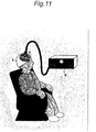
- Fig. 11 is a view showing a state thetin which a patient (an examinee) uses the repetitive transcranial magnetic stimulator according to the second embodiment of the present invention at home or the like on a daily basis without help of a professional operator.
- Fig. 11 shows the state in which the examinee wears the fixture of head for magnetic stimulation 2, to which the magnetic field generating means 8 to be connected to the magnetic stimulation control device 10 is fixed.
- a third embodiment according to the present invention to be described below relates to a method for manufacturing a fixture of a head, which decides the appropriate position of the magnetic field generating means for the brain and the cranium of the patient more accurately and automatically by using the repetitive transcranial magnetic stimulator shown in Fig. 1 and the optical navigation guide system shown in Fig. 3 to reflect the position to manufacturing of the fixture of the head, and thereby, faithfully recreates the appropriate position of the magnetic field generating means.
- Fig. 12 is a flow chart showing a schematic procedure of a method for manufacturing a fixture of the head according to the third embodiment of the present invention.
- Fig. 13 is a block diagram showing a relation among the computer 21, a display 25, an MRI image pickup apparatus 30, and a position grasping means 28, which are used by the third embodiment according to the present invention.
- Fig. 14 is a schematic flow chart showing the operation of the computer 21 to be used by the third embodiment according to the present invention.
- the detailed MRI image of the head of the examinee is taken by the MRI image pickup apparatus 30 to be sent to the computer 21 ( Fig. 14 , S02), and the computer 21 builds up a three-dimensional image relating to the head of the examinee based on this ( Fig. 14 , S04) ( Fig. 12 , Step 1).
- the image is taken along many parallel planes to slice the head of the examinee thinly (at an interval of 1 to 2 mm).
- the MRI image of the head may be taken along about 130 pieces of parallel planes at an interval of 2 mm, which are perpendicular to a center axis in a vertical direction of the head.
- Such an MRI image is hereinafter referred to as a "thin slice MRI image”.
- the computer 21 to be connected to the position grasping means 28 grasps in real time the data of the position and the direction of the magnetic field generating means 8 that are grasped by the position grasping means 28 ( Fig. 14 , S06). Further, the computer 21 calculates in real time the position, the direction and the angle of the brain (the cranium) of the examinee, and the positions, the directions, and the angles of the magnetic field generating means 8 and the generated magnetic field by using the above-described "thin slice MRI image" and displays them ( Fig. 14 , S08) (see Figs. 3 and 13 ).
- the computer 21 superimposes the position and direction data of the movable magnetic field generating means on the MRI image and displays them ( Fig. 12 , Step 2).
- the system that the computer 21 grasps the MRI image, the position of the head (the brain) of the examinee, a treatment bed, and the magnetic field generating means by connecting them; as described above, calculates in real time the position, the direction and the angle of the brain (the cranium), and the positions, the directions, and the angles of the magnetic field generating means 8 and the generated magnetic field; and displays them may be identical with those of the repetitive transcranial magnetic stimulator shown in Fig. 1 and the optical navigation guide system shown in Fig. 3 , which are described in the first embodiment explained in the first embodiment.
- the operator decides the relative positions, which are most effective for the examinee, of the magnetic field generating means 8 and of the generated magnetic field corresponding to the head of the examinee, and then, the operator instructs this decision to the computer 21 ( Fig. 14 , Step 10, Yes).
- the displayed image of the display 25 shown in Fig. 13 shows the state in which the position represented by "A" is decided to be a position of the position of the most effective generated magnetic field.
- the computer 21 Upon receipt of the decision instruction, the computer 21 records the MRI three-dimensional image representing a positional relation between the brain, the cranium, and the magnetic field generating means 8 in this decision time as a position displaying three-dimensional image ( Fig. 14 , S12) ( Fig. 12 , Step 3).
- the above-described position displaying three-dimensional image is built up by the MRI image.
- the MRI image of the head includes not only the information of the shape and the position relating to the brain but also the information of the shape and the position relating to the cranium and the skin of the head. Therefore, if the information of the shape of the head of the examinee and the information relating to the position, direction, and angle of the magnetic field generating means are particularly taken from the information of the above-described position displaying three-dimensional image, the image information to depict the relative positional relation between the shape of the head of the examinee and the magnetic field generating means 8 three-dimensionally is formed ( Fig. 12 , Step 4).
- the above-described image information to depict the relative positional relation three-dimensionally includes (1) the detailed shape information of the head of the examinee; (2) the detailed information of the shape of the nasal port and the shape of the ears; and (3) the information such that the strict relative position (the distance and the direction) of the magnetic field generating means to the target spot and the surface of the head of the examinee are quantified.
- an appropriate resin is used as a material, for example, due to the above-described information (1) and (2), an integrated-type of a fixture of the head (a helmet or the like) to be closed attached to and fit the head of the examinee can be generated.
- the MRI image pickup apparatus As an image pickup apparatus for imaging the head of the examinee, the MRI image pickup apparatus is used, however, other image pickup apparatus may be used as far as the pickup image data can be used by the optical navigation guide system and the information of the shape and the position relating to the brain and the information of the shape and the position relating to the cranium and the skin of the head can be collected.
- the image pickup apparatus may be a CT (Computed Tomography) apparatus and an ultrasonic apparatus or the like may be used.
- the material of the fixture of the head to be manufactured by the method for manufacturing the fixture of the head according to the third embodiment of the present invention is not limited to a resin.
- the fixture of the head to be generated is not limited to an integrated-type but may be configured by plural elements.
Landscapes
- Health & Medical Sciences (AREA)
- Engineering & Computer Science (AREA)
- Life Sciences & Earth Sciences (AREA)
- Biomedical Technology (AREA)
- Veterinary Medicine (AREA)
- Surgery (AREA)
- Nuclear Medicine, Radiotherapy & Molecular Imaging (AREA)
- Animal Behavior & Ethology (AREA)
- General Health & Medical Sciences (AREA)
- Public Health (AREA)
- Radiology & Medical Imaging (AREA)
- Heart & Thoracic Surgery (AREA)
- Medical Informatics (AREA)
- Molecular Biology (AREA)
- Neurosurgery (AREA)
- Oral & Maxillofacial Surgery (AREA)
- Pathology (AREA)
- Neurology (AREA)
- Robotics (AREA)
- Magnetic Treatment Devices (AREA)
- Electrotherapy Devices (AREA)
Claims (9)
- Verfahren zur Fertigung einer Befestigung (2) eines Kopfes zur Befestigung von Magnetfelderzeugungsmitteln (8), umfassend die Schritte von:Aufnehmen eines Bildes von einem Kopf eines Untersuchungskandidaten entlang vieler paralleler Ebenen, um Schnittbilder vom Kopf des Untersuchungskandidaten anzufertigen, wobei das Bild ein MRT-Bild ist;Einstellen eines Verhältnisses zwischen einem Koordinatensystem des Bildes und einem Koordinatensystem, das durch ein vorbestimmtes Positionserfassungsmittel (28) aufgebaut werden soll, um eine Position und eine Richtung des Magnetfelderzeugungsmittels (8) zu erfassen, und Übereinanderlagern der Positions- und Richtungsdaten des beweglichen Magnetfelderzeugungsmittels in Bezug auf das Bild;Fixieren der Positions- und der Richtungsdaten des Magnetfelderzeugungsmittels (8) zu einem bestimmten Zeitpunkt im Bild, bei dem die Positions- und Richtungsdaten des beweglichen Magnetfelderzeugungsmittels übereinandergelagert sind, und Aufzeichnen derselben zusammen mit dem Bild, und dadurch Erzeugen eines dreidimensionalen MRT-Bildes, das ein Positionsverhältnis zwischen dem Gehirn, dem Schädel und dem Magnetfelderzeugungsmittel in dem Befestigungsschritt als ein positionsanzeigendes dreidimensionales Bildes darstellt;Festlegen der Daten, die ein relatives Verhältnis zwischen der Oberfläche des Kopfes des Untersuchungskandidaten und dem Magnetfelderzeugungsmittel (8) aufzeigen, basierend auf ersten Koordinatendaten, die die Oberfläche des Kopfes des Untersuchungskandidaten darstellen, der in dem erzeugten dreidimensionalen MRT-Bild beinhaltet ist, und zweiten Koordinatendaten, die die Position und die Richtung des aufgezeichneten Magnetfelderzeugungsmittels darstellen; undBilden einer Befestigung (2) eines Kopfes, begleitet von einem Magnetfelderzeugungsmittel-Befestigungsteil (14), um eine relative Position des aufgezeichneten Magnetfelderzeugungsmittels in Bezug auf die Oberfläche des Kopfes des Untersuchungskandidaten basierend auf den Daten, die das oben beschriebene relative Verhältnis aufzeigen, zum engen Anbringen an der Oberfläche des Kopfes des Untersuchungskandidaten nachzubilden,wobei ein relatives Positionsverhältnis des Magnetfelderzeugungsmittels (8), das durch die Positions- und die Richtungsdaten des im Aufzeichnungsschritt in Bezug auf den Kopf des Untersuchungskandidaten zu befestigenden Magnetfelderzeugungsmittels dargestellt wird, ein Positionsverhältnis ist, sodass der höchste Punkt einer Intensität eines elektrischen Stroms, der durch ein Magnetfeld induziert werden soll, das durch das Magnetfelderzeugungsmittel erzeugt werden soll, ständig auf einem Zielpunkt mit einem Durchmesser von nicht mehr als 10 mm angeordnet ist, der abhängig von jedem der Untersuchungskandidaten ist und sich in einem primären motorischen Bereich (M1) eines Gehirns innerhalb eines Schädels befindet, und eine Richtung eines Magnetfelds, das durch das Magnetfelderzeugungsmittel erzeugt werden soll, und eine Richtung des Zielpunktes in ein festes Verhältnis gebracht werden.
- Teilebausatz, umfassend ein Magnetfelderzeugungsmittel (8) beinhaltend eine Spule und eine Befestigung (2) eines Kopfes zur transkranialen Magnetstimulation zur Verminderung von Deafferenzschmerzen, umfassend Befestigungsmittel (14) zur lösbaren Befestigung des Magnetfelderzeugungsmittels (8),
wobei die Befestigung des Kopfes angepasst ist, um einen zu befestigenden Kopf eines Untersuchungskandidaten zu bedecken und um mit einer Form des Kopfes in Eingriff zu kommen, die einem Untersuchungskandidaten eigen ist, wobei, wenn das Magnetfelderzeugungsmittel mit den Befestigungsmitteln (14) befestigt ist, ein relatives Positionsverhältnis des Magnetfelderzeugungsmittels (8) in Bezug auf den Kopf des Untersuchungskandidaten konstant gehalten wird, sodass der höchste Punkt einer Intensität eines elektrischen Stroms, der durch ein von dem Magnetfelderzeugungsmittel (8) zu erzeugendes Magnetfeld induziert werden soll, ständig auf einem Zielpunkt mit einem Durchmesser von nicht mehr als 10 mm angeordnet ist, der abhängig von jedem der Untersuchungskandidaten ist und sich in einem primären motorischen Bereich (M1) einer Hirnrinde innerhalb eines Schädels befindet, und eine Richtung eines von dem Magnetfelderzeugungsmittel zu erzeugenden Magnetfeldes und eine Richtung des Zielpunktes in ein festes Verhältnis gebracht werden; wobei
die Befestigung (2) eines Kopfes
einen Hauptkörper (4), der die Befestigungsmittel auf ihm angebracht aufweist;
ein Schalenteil (6), das zwischen dem Hauptkörper (4) und dem Kopf des Untersuchungskandidaten angeordnet ist; und
eine Schalenteilbefestigung (12) zum Befestigen des Schalenteils an dem Hauptkörper beinhaltet;
und wobei das Schalenteil (6) so ausgeformt ist, dass es mit der Form des Kopfes in Eingriff kommt, die dem Untersuchungskandidaten eigen ist. - Bausatz nach Anspruch 2, wobei
das Schalenteil (6) eine Folie ist, die aus einem thermoplastischen Harz hergestellt ist, und aus einer Folie hergestellt ist, die so modifiziert ist, dass sie mit der Form des Kopfes in Eingriff kommt, die dem Untersuchungskandidaten eigen ist. - Bausatz nach Anspruch 3, wobei
die aus einem thermoplastischen Harz hergestellte Folie eine gitternetzartige Folie ist. - Bausatz nach Anspruch 4, wobei
die Form des Kopfes, die dem Untersuchungskandidaten eigen ist, eine Form einer Nasenöffnung oder eine Form von Ohren des Untersuchungskandidaten ist. - Bausatz nach einem der Ansprüche 2 bis 5, wobei
das Befestigungsmittel (14) einen Vorsprungsteil beinhaltet, der einen polygonalen Querschnitt aufweist;
und ein ausgesparter Abschnitt, der in dem Magnetfelderzeugungsmittel (8) ausgebildet ist, die Befestigungsmittel (14) an der Befestigung (2) des Kopfes befestigt, die mit dem Vorsprungsteil in Eingriff kommt. - Transkranialer Magnetstimulator, umfassend:einen Teilebausatz, umfassend ein Magnetfelderzeugungsmittel (8), das eine Spule und eine Befestigung (2) eines Kopfes für eine transkraniale Magnetstimulation zur Verminderung von Deafferenzschmerzen nach einem der Ansprüche 2 bis 6 beinhaltet;das Magnetfelderzeugungsmittel (8), das die Spule beinhaltet, die lösbar an der Befestigung des Kopfes zu befestigen ist; undeine Magnetstimulations-Steuervorrichtung (10) zum Induzieren eines Magnetfeldes durch Leiten eines elektrischen Stroms durch die Spule des Magnetfelderzeugungsmittels (8).
- Transkranialer Magnetstimulator (1) nach Anspruch 7 zum Hinzufügen eines Magnetstimulus zu einem Kopf eines Untersuchungskandidaten unter Verwendung eines Magnetfelderzeugungsmittels (8), das außerhalb des Kopfes vorhanden ist, umfassend:ein optisches Positionserfassungsmittel (28), das konfiguriert ist, um die relative Position des Magnetfelderzeugungsmittels (8) zur Hirnrinde des Untersuchungskandidaten zu erfassen;einen Computer (21), der konfiguriert ist, um ein dreidimensionales MRT-Bild aufzuzeichnen, das ein Positionsverhältnis zwischen dem Gehirn, dem Schädel und dem Magnetfelderzeugungsmittel als eine Position darstellt, die ein dreidimensionales Bild anzeigt, und um die Position des Magnetfelderzeugungsmittels (8) in Bezug auf die Hirnrinde des Untersuchungskandidaten in Echtzeit zu berechnen und auf einer Anzeige (25) anzuzeigen, basierend auf einer Bildinformation des Kopfes, die vor der Behandlung aufgenommen wurde, und der Ausgabeinformation des optischen Positionserfassungsmittels (28), wobei die Bildinformation des Kopfes eine MRT-Bildinformation ist; undwobei die Befestigung (2) des Kopfes ein Befestigungsmittel aufweist, das das Magnetfelderzeugungsmittel (8) lösbar befestigt, so dass eine Richtung des von dem magnetischen Erzeugungsmittel (8) zu erzeugenden Magnetfeldes und eine Richtung des Zielpunktes, auf den der magnetische Reiz hinzugefügt wird, in ein festes Verhältnis gebracht werden.
- Transkranialer Magnetstimulator (1) nach Anspruch 8, wobei
das optische Positionserfassungsmittel konfiguriert ist, um in der Lage zu sein, die relative Position basierend auf der Positionsinformation eines auf dem Kopf des Untersuchungskandidaten angebrachten und in der Bildinformation des Kopfes beinhalteten Markers zu erfassen, wobei die Positionsinformation erfasst wird, indem das Bild eines ersten Positionsanzeigemittels (24) aufgenommen wird, das einer Behandlungsliege bereitgestellt wird, und die Positionsinformation erfasst wird, indem das Bild eines zweiten Positionsanzeigemittels (26) aufgenommen wird, das an dem Magnetfelderzeugungsmittel (8) angebracht ist.
Applications Claiming Priority (2)
| Application Number | Priority Date | Filing Date | Title |
|---|---|---|---|
| JP2006114116 | 2006-04-18 | ||
| PCT/JP2007/058411 WO2007123147A1 (ja) | 2006-04-18 | 2007-04-18 | 経頭蓋磁気刺激用頭部固定具及び経頭蓋磁気刺激装置 |
Publications (3)
| Publication Number | Publication Date |
|---|---|
| EP2008687A1 EP2008687A1 (de) | 2008-12-31 |
| EP2008687A4 EP2008687A4 (de) | 2010-11-10 |
| EP2008687B1 true EP2008687B1 (de) | 2019-11-13 |
Family
ID=38625047
Family Applications (1)
| Application Number | Title | Priority Date | Filing Date |
|---|---|---|---|
| EP07741847.3A Active EP2008687B1 (de) | 2006-04-18 | 2007-04-18 | Werkzeug zur befestigung eines transkranialen magnetischen stimulationskopfes und transkranialer magnetischer stimulator |
Country Status (4)
| Country | Link |
|---|---|
| US (1) | US8568287B2 (de) |
| EP (1) | EP2008687B1 (de) |
| JP (2) | JP5449768B2 (de) |
| WO (1) | WO2007123147A1 (de) |
Families Citing this family (50)
| Publication number | Priority date | Publication date | Assignee | Title |
|---|---|---|---|---|
| US8047979B2 (en) | 2001-04-20 | 2011-11-01 | Mclean Hospital Corporation | Magnetic field treatment techniques |
| US8118722B2 (en) | 2003-03-07 | 2012-02-21 | Neuronetics, Inc. | Reducing discomfort caused by electrical stimulation |
| US7153256B2 (en) | 2003-03-07 | 2006-12-26 | Neuronetics, Inc. | Reducing discomfort caused by electrical stimulation |
| US8052591B2 (en) | 2006-05-05 | 2011-11-08 | The Board Of Trustees Of The Leland Stanford Junior University | Trajectory-based deep-brain stereotactic transcranial magnetic stimulation |
| US8267850B2 (en) * | 2007-11-27 | 2012-09-18 | Cervel Neurotech, Inc. | Transcranial magnet stimulation of deep brain targets |
| US9352167B2 (en) | 2006-05-05 | 2016-05-31 | Rio Grande Neurosciences, Inc. | Enhanced spatial summation for deep-brain transcranial magnetic stimulation |
| US8956274B2 (en) * | 2007-08-05 | 2015-02-17 | Cervel Neurotech, Inc. | Transcranial magnetic stimulation field shaping |
| US20100185042A1 (en) * | 2007-08-05 | 2010-07-22 | Schneider M Bret | Control and coordination of transcranial magnetic stimulation electromagnets for modulation of deep brain targets |
| US20090099405A1 (en) * | 2007-08-05 | 2009-04-16 | Neostim, Inc. | Monophasic multi-coil arrays for trancranial magnetic stimulation |
| US20100256439A1 (en) * | 2007-08-13 | 2010-10-07 | Schneider M Bret | Gantry and switches for position-based triggering of tms pulses in moving coils |
| AU2008288967A1 (en) * | 2007-08-20 | 2009-02-26 | Cervel NeuroTech, Inc | Firing patterns for deep brain transcranial magnetic stimulation |
| WO2009033192A1 (en) * | 2007-09-09 | 2009-03-12 | Neostim, Inc. | Focused magnetic fields |
| WO2009049068A1 (en) * | 2007-10-09 | 2009-04-16 | Neostim, Inc. | Display of modeled magnetic fields |
| US20100298623A1 (en) * | 2007-10-24 | 2010-11-25 | Mishelevich David J | Intra-session control of transcranial magnetic stimulation |
| WO2009055780A1 (en) * | 2007-10-26 | 2009-04-30 | Neostim, Inc. | Transcranial magnetic stimulation with protection of magnet-adjacent structures |
| JP2009261814A (ja) * | 2008-04-30 | 2009-11-12 | Ge Medical Systems Global Technology Co Llc | 磁気刺激用コイル、磁気刺激装置、および磁気刺激システム |
| JP2010082400A (ja) * | 2008-09-17 | 2010-04-15 | Besutekku:Kk | 細胞脱分化方法、細胞脱分化装置及び細胞脱分化評価方法 |
| US8795148B2 (en) * | 2009-10-26 | 2014-08-05 | Cervel Neurotech, Inc. | Sub-motor-threshold stimulation of deep brain targets using transcranial magnetic stimulation |
| WO2010080879A2 (en) | 2009-01-07 | 2010-07-15 | Neostim, Inc. | Shaped coils for transcranial magnetic stimulation |
| US8591392B2 (en) * | 2009-04-03 | 2013-11-26 | Neuronix Ltd. | Method and system for neurological treatment |
| JP5622153B2 (ja) * | 2009-06-15 | 2014-11-12 | 国立大学法人大阪大学 | 磁気刺激装置 |
| WO2012009603A2 (en) | 2010-07-16 | 2012-01-19 | Cervel Neurotech, Inc. | Transcranial magnetic stimulation for altering susceptibility of tissue to pharmaceuticals and radiation |
| CN101912668B (zh) * | 2010-07-26 | 2013-04-10 | 香港脑泰科技有限公司 | 一种导航经颅磁刺激治疗系统 |
| JP5896109B2 (ja) * | 2010-11-25 | 2016-03-30 | 国立大学法人大阪大学 | 治療用磁気コイルユニット |
| ES2818078T3 (es) | 2011-03-09 | 2021-04-09 | Univ Osaka | Dispositivo de procesamiento de datos de imagen y aparato de estimulación magnética transcraneal |
| US10342987B2 (en) | 2011-04-28 | 2019-07-09 | Osaka University | Therapeutic electromagnetic stimulation device and method of generating custom data pairs used in said device |
| EP2714192B1 (de) * | 2011-06-03 | 2021-03-10 | Nexstim Oyj | Verfahren zur kombination von anatomischen konnektivitätsmustern und navigierter hirnstimulation |
| JP6267960B2 (ja) * | 2011-10-24 | 2018-01-24 | 帝人ファーマ株式会社 | 経頭蓋磁気刺激システム |
| JP2013135735A (ja) * | 2011-12-28 | 2013-07-11 | Advanced Telecommunication Research Institute International | 脳刺激付与装置 |
| US10743815B2 (en) * | 2012-01-19 | 2020-08-18 | Cerebrotech Medical Systems, Inc. | Detection and analysis of spatially varying fluid levels using magnetic signals |
| US9254394B2 (en) * | 2013-02-21 | 2016-02-09 | Brainsway, Ltd. | Central base coils for deep transcranial magnetic stimulation |
| US11730970B2 (en) | 2013-03-14 | 2023-08-22 | The Methodist Hospital | Method and apparatus for providing transcranial magnetic stimulation (TMS) to an individual |
| AU2014250542B2 (en) * | 2013-04-02 | 2018-12-06 | Teijin Limited | Head positioning device, medical system, medical instrument positioning device, and holding shell |
| CN105050658B (zh) | 2013-04-02 | 2017-09-12 | 帝人制药株式会社 | 磁刺激装置 |
| US20160243376A1 (en) * | 2013-10-01 | 2016-08-25 | The Magstim Company Limited | Magnetic Stimulator Arrangement |
| JP6550660B2 (ja) | 2013-12-24 | 2019-07-31 | 国立大学法人大阪大学 | 操作教示装置および経頭蓋磁気刺激装置 |
| JPWO2016093213A1 (ja) * | 2014-12-09 | 2017-09-14 | 帝人ファーマ株式会社 | 励磁コイル及びコイルユニット |
| US10874870B2 (en) * | 2016-05-05 | 2020-12-29 | The Methodist Hospital | Method and apparatus for providing transcranial magnetic stimulation (TMS) to an individual |
| WO2017195309A1 (ja) * | 2016-05-12 | 2017-11-16 | 株式会社日立製作所 | エネルギー照射装置 |
| CN108014420B (zh) * | 2016-11-02 | 2023-11-14 | 北京脑泰科技发展有限公司 | 一种可对手柄姿态进行定位的经颅磁刺激仪 |
| JP7190442B2 (ja) * | 2017-04-05 | 2022-12-15 | メドトロニック,インコーポレイテッド | 植込み型医療電気システムを再充電するための組立体およびそのヘッドギア |
| KR102403686B1 (ko) * | 2020-05-15 | 2022-05-31 | 뉴로핏 주식회사 | 뇌자극 위치 제공장치 및 방법 |
| CN113577565B (zh) * | 2021-08-05 | 2022-03-04 | 安徽医科大学 | 一种卧式经颅磁刺激器的导航定位装置 |
| CN113813509A (zh) * | 2021-08-24 | 2021-12-21 | 杭州师范大学 | 磁共振外加标志点的精准定位经颅磁刺激靶点方法 |
| CN114288560B (zh) * | 2021-12-30 | 2025-09-16 | 西安科悦医疗技术有限公司 | 经颅磁刺激导航过程的三维配准方法、系统及计算机设备 |
| JP7802945B2 (ja) * | 2022-01-25 | 2026-01-20 | レメド ブレインスティム カンパニー リミテッド | ヘルメット型磁気刺激装置 |
| CN115910356B (zh) * | 2022-11-11 | 2023-07-25 | 深圳职业技术学院 | 基于经颅磁刺激线圈电磁场模拟的磁场刺激效果评估方法 |
| CN121666259A (zh) | 2023-08-04 | 2026-03-13 | 帝人制药株式会社 | 线圈保持单元和经颅磁刺激装置 |
| WO2025170003A1 (ja) * | 2024-02-07 | 2025-08-14 | 国立大学法人東京大学 | 経頭蓋磁気刺激コイル |
| WO2026015871A1 (en) * | 2024-07-11 | 2026-01-15 | Adam Wallach | Articles and methods for treating mitochondrial dysfunction |
Citations (1)
| Publication number | Priority date | Publication date | Assignee | Title |
|---|---|---|---|---|
| US20050154426A1 (en) * | 2002-05-09 | 2005-07-14 | Boveja Birinder R. | Method and system for providing therapy for neuropsychiatric and neurological disorders utilizing transcranical magnetic stimulation and pulsed electrical vagus nerve(s) stimulation |
Family Cites Families (10)
| Publication number | Priority date | Publication date | Assignee | Title |
|---|---|---|---|---|
| JPH07148279A (ja) | 1993-11-29 | 1995-06-13 | Hidenao Akatsu | 放射線治療用胸部固定装置 |
| JPH1076020A (ja) * | 1996-09-04 | 1998-03-24 | Ge Yokogawa Medical Syst Ltd | 放射線治療位置合わせ方法、医用装置および位置合わせ用紙 |
| AU764768B2 (en) * | 1999-07-23 | 2003-08-28 | University Of Florida | Ultrasonic guidance of target structures for medical procedures |
| GB0015683D0 (en) * | 2000-06-28 | 2000-08-16 | Depuy Int Ltd | Apparatus for positioning a surgical instrument |
| DE50106039D1 (de) * | 2001-06-28 | 2005-06-02 | Brainlab Ag | Vorrichtung für transcraniale magnetische Stimulation |
| FI114613B (fi) * | 2001-10-17 | 2004-11-30 | Nexstim Oy | Menetelmä ja laite magneettistimulaation annoslaskentaa varten |
| AU2003241457A1 (en) | 2002-05-17 | 2003-12-02 | Musc Foundation For Research Development | Method, apparatus, and system for automatically positioning a probe or sensor |
| WO2004032781A1 (en) | 2002-10-04 | 2004-04-22 | Med-Tec Iowa, Inc. | Reinforced thermoplastic patient restraints for radiation therapy |
| US7153256B2 (en) * | 2003-03-07 | 2006-12-26 | Neuronetics, Inc. | Reducing discomfort caused by electrical stimulation |
| WO2007103475A2 (en) * | 2006-03-07 | 2007-09-13 | Beth Israel Deaconess Medical Center, Inc. | Transcranial magnetic stimulation (tms) methods and apparatus |
-
2007
- 2007-04-18 EP EP07741847.3A patent/EP2008687B1/de active Active
- 2007-04-18 JP JP2008512132A patent/JP5449768B2/ja not_active Expired - Fee Related
- 2007-04-18 US US12/226,473 patent/US8568287B2/en not_active Expired - Fee Related
- 2007-04-18 WO PCT/JP2007/058411 patent/WO2007123147A1/ja not_active Ceased
-
2013
- 2013-01-07 JP JP2013000674A patent/JP2013059683A/ja active Pending
Patent Citations (1)
| Publication number | Priority date | Publication date | Assignee | Title |
|---|---|---|---|---|
| US20050154426A1 (en) * | 2002-05-09 | 2005-07-14 | Boveja Birinder R. | Method and system for providing therapy for neuropsychiatric and neurological disorders utilizing transcranical magnetic stimulation and pulsed electrical vagus nerve(s) stimulation |
Also Published As
| Publication number | Publication date |
|---|---|
| JP2013059683A (ja) | 2013-04-04 |
| EP2008687A1 (de) | 2008-12-31 |
| US20090187062A1 (en) | 2009-07-23 |
| EP2008687A4 (de) | 2010-11-10 |
| JP5449768B2 (ja) | 2014-03-19 |
| WO2007123147A1 (ja) | 2007-11-01 |
| US8568287B2 (en) | 2013-10-29 |
| JPWO2007123147A1 (ja) | 2009-09-03 |
Similar Documents
| Publication | Publication Date | Title |
|---|---|---|
| EP2008687B1 (de) | Werkzeug zur befestigung eines transkranialen magnetischen stimulationskopfes und transkranialer magnetischer stimulator | |
| EP3106204B1 (de) | Intrazerebrales stromsimulationsverfahren und vorrichtung dafür sowie transkranielles magnetisches stimulationssystem mit intrazerebraler stromsimulationsvorrichtung | |
| US6827681B2 (en) | Method and device for transcranial magnetic stimulation | |
| JP6384967B2 (ja) | コイル装置及び経頭蓋磁気刺激システム | |
| US20130338424A1 (en) | Transcranial magnetic stimulation (tms) methods and apparatus | |
| EP2958621B1 (de) | Kreisspulen zur transkranialen magnetischen tiefenhirnstimulation | |
| EP2666515A1 (de) | Transkraneale Magnetstimulation für kleine Tiere | |
| US20140200388A1 (en) | Concurrent stimulation of deep and superficial brain regions | |
| JP4313559B2 (ja) | 磁気刺激量の計算方法及び装置 | |
| US20050033380A1 (en) | Method and device for stimulating the brain | |
| CN111493820A (zh) | 用于向个体提供经颅磁刺激(tms)的方法和设备 | |
| KR20080065577A (ko) | 경두개 전기 자극 유도 기술 | |
| Kantelhardt et al. | Robot-assisted image-guided transcranial magnetic stimulation for somatotopic mapping of the motor cortex: a clinical pilot study | |
| CN109475749B (zh) | 用于向个体提供经颅磁刺激(tms)的方法和设备 | |
| IL321216A (en) | Magnetic-stimulation coil | |
| KR20210126835A (ko) | 뇌질환 개선 장치 및 그의 제어 방법 | |
| Lee et al. | Stimulation strength and focality of electroconvulsive therapy and magnetic seizure therapy in a realistic head model | |
| Ilmoniemi et al. | Transcranial magnetic stimulation coils | |
| CN218305838U (zh) | 一种经颅磁刺激治疗头盔 | |
| UA141430U (uk) | Пристрій для позиціювання котушки магнітного стимулятора | |
| Dobre et al. | A numerical model for the assessment of the transcranial magnetic stimulation | |
| Patuzzo et al. | New Techniques for Stereotactic Neurosurgery Based on Mask with Customized Dental Bite | |
| Koehler et al. | Formalism for Anatomy-Independent Projection and Optimization of Transcranial Magnetic Stimulation Coils | |
| Bertino et al. | Has white noise acoustic stimulation a modulatory effect on the aperiodic component of EEG activity? | |
| Nurmi | Designing and building mTMS transducers for bihemispheric brain stimulation |
Legal Events
| Date | Code | Title | Description |
|---|---|---|---|
| PUAI | Public reference made under article 153(3) epc to a published international application that has entered the european phase |
Free format text: ORIGINAL CODE: 0009012 |
|
| 17P | Request for examination filed |
Effective date: 20081103 |
|
| AK | Designated contracting states |
Kind code of ref document: A1 Designated state(s): AT BE BG CH CY CZ DE DK EE ES FI FR GB GR HU IE IS IT LI LT LU LV MC MT NL PL PT RO SE SI SK TR |
|
| AX | Request for extension of the european patent |
Extension state: AL BA HR MK RS |
|
| RAP1 | Party data changed (applicant data changed or rights of an application transferred) |
Owner name: TEIJIN PHARMA LIMITED Owner name: OSAKA UNIVERSITY |
|
| A4 | Supplementary search report drawn up and despatched |
Effective date: 20101012 |
|
| DAX | Request for extension of the european patent (deleted) | ||
| 17Q | First examination report despatched |
Effective date: 20130726 |
|
| STAA | Information on the status of an ep patent application or granted ep patent |
Free format text: STATUS: EXAMINATION IS IN PROGRESS |
|
| GRAP | Despatch of communication of intention to grant a patent |
Free format text: ORIGINAL CODE: EPIDOSNIGR1 |
|
| STAA | Information on the status of an ep patent application or granted ep patent |
Free format text: STATUS: GRANT OF PATENT IS INTENDED |
|
| INTG | Intention to grant announced |
Effective date: 20190605 |
|
| GRAS | Grant fee paid |
Free format text: ORIGINAL CODE: EPIDOSNIGR3 |
|
| GRAJ | Information related to disapproval of communication of intention to grant by the applicant or resumption of examination proceedings by the epo deleted |
Free format text: ORIGINAL CODE: EPIDOSDIGR1 |
|
| GRAL | Information related to payment of fee for publishing/printing deleted |
Free format text: ORIGINAL CODE: EPIDOSDIGR3 |
|
| STAA | Information on the status of an ep patent application or granted ep patent |
Free format text: STATUS: EXAMINATION IS IN PROGRESS |
|
| GRAR | Information related to intention to grant a patent recorded |
Free format text: ORIGINAL CODE: EPIDOSNIGR71 |
|
| STAA | Information on the status of an ep patent application or granted ep patent |
Free format text: STATUS: GRANT OF PATENT IS INTENDED |
|
| GRAA | (expected) grant |
Free format text: ORIGINAL CODE: 0009210 |
|
| STAA | Information on the status of an ep patent application or granted ep patent |
Free format text: STATUS: THE PATENT HAS BEEN GRANTED |
|
| INTC | Intention to grant announced (deleted) | ||
| AK | Designated contracting states |
Kind code of ref document: B1 Designated state(s): AT BE BG CH CY CZ DE DK EE ES FI FR GB GR HU IE IS IT LI LT LU LV MC MT NL PL PT RO SE SI SK TR |
|
| INTG | Intention to grant announced |
Effective date: 20191007 |
|
| REG | Reference to a national code |
Ref country code: GB Ref legal event code: FG4D |
|
| REG | Reference to a national code |
Ref country code: AT Ref legal event code: REF Ref document number: 1201045 Country of ref document: AT Kind code of ref document: T Effective date: 20191115 Ref country code: CH Ref legal event code: EP |
|
| REG | Reference to a national code |
Ref country code: DE Ref legal event code: R096 Ref document number: 602007059486 Country of ref document: DE |
|
| REG | Reference to a national code |
Ref country code: IE Ref legal event code: FG4D |
|
| REG | Reference to a national code |
Ref country code: NL Ref legal event code: MP Effective date: 20191113 |
|
| REG | Reference to a national code |
Ref country code: LT Ref legal event code: MG4D |
|
| PG25 | Lapsed in a contracting state [announced via postgrant information from national office to epo] |
Ref country code: PT Free format text: LAPSE BECAUSE OF FAILURE TO SUBMIT A TRANSLATION OF THE DESCRIPTION OR TO PAY THE FEE WITHIN THE PRESCRIBED TIME-LIMIT Effective date: 20200313 Ref country code: PL Free format text: LAPSE BECAUSE OF FAILURE TO SUBMIT A TRANSLATION OF THE DESCRIPTION OR TO PAY THE FEE WITHIN THE PRESCRIBED TIME-LIMIT Effective date: 20191113 Ref country code: GR Free format text: LAPSE BECAUSE OF FAILURE TO SUBMIT A TRANSLATION OF THE DESCRIPTION OR TO PAY THE FEE WITHIN THE PRESCRIBED TIME-LIMIT Effective date: 20200214 Ref country code: ES Free format text: LAPSE BECAUSE OF FAILURE TO SUBMIT A TRANSLATION OF THE DESCRIPTION OR TO PAY THE FEE WITHIN THE PRESCRIBED TIME-LIMIT Effective date: 20191113 Ref country code: LT Free format text: LAPSE BECAUSE OF FAILURE TO SUBMIT A TRANSLATION OF THE DESCRIPTION OR TO PAY THE FEE WITHIN THE PRESCRIBED TIME-LIMIT Effective date: 20191113 Ref country code: NL Free format text: LAPSE BECAUSE OF FAILURE TO SUBMIT A TRANSLATION OF THE DESCRIPTION OR TO PAY THE FEE WITHIN THE PRESCRIBED TIME-LIMIT Effective date: 20191113 Ref country code: SE Free format text: LAPSE BECAUSE OF FAILURE TO SUBMIT A TRANSLATION OF THE DESCRIPTION OR TO PAY THE FEE WITHIN THE PRESCRIBED TIME-LIMIT Effective date: 20191113 Ref country code: LV Free format text: LAPSE BECAUSE OF FAILURE TO SUBMIT A TRANSLATION OF THE DESCRIPTION OR TO PAY THE FEE WITHIN THE PRESCRIBED TIME-LIMIT Effective date: 20191113 Ref country code: FI Free format text: LAPSE BECAUSE OF FAILURE TO SUBMIT A TRANSLATION OF THE DESCRIPTION OR TO PAY THE FEE WITHIN THE PRESCRIBED TIME-LIMIT Effective date: 20191113 Ref country code: BG Free format text: LAPSE BECAUSE OF FAILURE TO SUBMIT A TRANSLATION OF THE DESCRIPTION OR TO PAY THE FEE WITHIN THE PRESCRIBED TIME-LIMIT Effective date: 20200213 |
|
| PG25 | Lapsed in a contracting state [announced via postgrant information from national office to epo] |
Ref country code: IS Free format text: LAPSE BECAUSE OF FAILURE TO SUBMIT A TRANSLATION OF THE DESCRIPTION OR TO PAY THE FEE WITHIN THE PRESCRIBED TIME-LIMIT Effective date: 20200313 |
|
| PG25 | Lapsed in a contracting state [announced via postgrant information from national office to epo] |
Ref country code: EE Free format text: LAPSE BECAUSE OF FAILURE TO SUBMIT A TRANSLATION OF THE DESCRIPTION OR TO PAY THE FEE WITHIN THE PRESCRIBED TIME-LIMIT Effective date: 20191113 Ref country code: RO Free format text: LAPSE BECAUSE OF FAILURE TO SUBMIT A TRANSLATION OF THE DESCRIPTION OR TO PAY THE FEE WITHIN THE PRESCRIBED TIME-LIMIT Effective date: 20191113 Ref country code: CZ Free format text: LAPSE BECAUSE OF FAILURE TO SUBMIT A TRANSLATION OF THE DESCRIPTION OR TO PAY THE FEE WITHIN THE PRESCRIBED TIME-LIMIT Effective date: 20191113 Ref country code: DK Free format text: LAPSE BECAUSE OF FAILURE TO SUBMIT A TRANSLATION OF THE DESCRIPTION OR TO PAY THE FEE WITHIN THE PRESCRIBED TIME-LIMIT Effective date: 20191113 |
|
| REG | Reference to a national code |
Ref country code: DE Ref legal event code: R097 Ref document number: 602007059486 Country of ref document: DE |
|
| REG | Reference to a national code |
Ref country code: AT Ref legal event code: MK05 Ref document number: 1201045 Country of ref document: AT Kind code of ref document: T Effective date: 20191113 |
|
| PG25 | Lapsed in a contracting state [announced via postgrant information from national office to epo] |
Ref country code: SK Free format text: LAPSE BECAUSE OF FAILURE TO SUBMIT A TRANSLATION OF THE DESCRIPTION OR TO PAY THE FEE WITHIN THE PRESCRIBED TIME-LIMIT Effective date: 20191113 |
|
| PLBE | No opposition filed within time limit |
Free format text: ORIGINAL CODE: 0009261 |
|
| STAA | Information on the status of an ep patent application or granted ep patent |
Free format text: STATUS: NO OPPOSITION FILED WITHIN TIME LIMIT |
|
| 26N | No opposition filed |
Effective date: 20200814 |
|
| PG25 | Lapsed in a contracting state [announced via postgrant information from national office to epo] |
Ref country code: MC Free format text: LAPSE BECAUSE OF FAILURE TO SUBMIT A TRANSLATION OF THE DESCRIPTION OR TO PAY THE FEE WITHIN THE PRESCRIBED TIME-LIMIT Effective date: 20191113 Ref country code: SI Free format text: LAPSE BECAUSE OF FAILURE TO SUBMIT A TRANSLATION OF THE DESCRIPTION OR TO PAY THE FEE WITHIN THE PRESCRIBED TIME-LIMIT Effective date: 20191113 Ref country code: AT Free format text: LAPSE BECAUSE OF FAILURE TO SUBMIT A TRANSLATION OF THE DESCRIPTION OR TO PAY THE FEE WITHIN THE PRESCRIBED TIME-LIMIT Effective date: 20191113 |
|
| REG | Reference to a national code |
Ref country code: CH Ref legal event code: PL |
|
| PG25 | Lapsed in a contracting state [announced via postgrant information from national office to epo] |
Ref country code: LI Free format text: LAPSE BECAUSE OF NON-PAYMENT OF DUE FEES Effective date: 20200430 Ref country code: FR Free format text: LAPSE BECAUSE OF NON-PAYMENT OF DUE FEES Effective date: 20200430 Ref country code: LU Free format text: LAPSE BECAUSE OF NON-PAYMENT OF DUE FEES Effective date: 20200418 Ref country code: IT Free format text: LAPSE BECAUSE OF FAILURE TO SUBMIT A TRANSLATION OF THE DESCRIPTION OR TO PAY THE FEE WITHIN THE PRESCRIBED TIME-LIMIT Effective date: 20191113 Ref country code: CH Free format text: LAPSE BECAUSE OF NON-PAYMENT OF DUE FEES Effective date: 20200430 |
|
| REG | Reference to a national code |
Ref country code: BE Ref legal event code: MM Effective date: 20200430 |
|
| PG25 | Lapsed in a contracting state [announced via postgrant information from national office to epo] |
Ref country code: BE Free format text: LAPSE BECAUSE OF NON-PAYMENT OF DUE FEES Effective date: 20200430 |
|
| GBPC | Gb: european patent ceased through non-payment of renewal fee |
Effective date: 20200418 |
|
| PG25 | Lapsed in a contracting state [announced via postgrant information from national office to epo] |
Ref country code: GB Free format text: LAPSE BECAUSE OF NON-PAYMENT OF DUE FEES Effective date: 20200418 Ref country code: IE Free format text: LAPSE BECAUSE OF NON-PAYMENT OF DUE FEES Effective date: 20200418 |
|
| PGFP | Annual fee paid to national office [announced via postgrant information from national office to epo] |
Ref country code: DE Payment date: 20210420 Year of fee payment: 15 |
|
| PG25 | Lapsed in a contracting state [announced via postgrant information from national office to epo] |
Ref country code: TR Free format text: LAPSE BECAUSE OF FAILURE TO SUBMIT A TRANSLATION OF THE DESCRIPTION OR TO PAY THE FEE WITHIN THE PRESCRIBED TIME-LIMIT Effective date: 20191113 Ref country code: MT Free format text: LAPSE BECAUSE OF FAILURE TO SUBMIT A TRANSLATION OF THE DESCRIPTION OR TO PAY THE FEE WITHIN THE PRESCRIBED TIME-LIMIT Effective date: 20191113 Ref country code: CY Free format text: LAPSE BECAUSE OF FAILURE TO SUBMIT A TRANSLATION OF THE DESCRIPTION OR TO PAY THE FEE WITHIN THE PRESCRIBED TIME-LIMIT Effective date: 20191113 |
|
| REG | Reference to a national code |
Ref country code: DE Ref legal event code: R119 Ref document number: 602007059486 Country of ref document: DE |
|
| PG25 | Lapsed in a contracting state [announced via postgrant information from national office to epo] |
Ref country code: DE Free format text: LAPSE BECAUSE OF NON-PAYMENT OF DUE FEES Effective date: 20221103 |