EP2008736B1 - Machine-outil et procédé destinés à l'évacuation d'une partie d'une pièce à usiner - Google Patents
Machine-outil et procédé destinés à l'évacuation d'une partie d'une pièce à usiner Download PDFInfo
- Publication number
- EP2008736B1 EP2008736B1 EP20070012867 EP07012867A EP2008736B1 EP 2008736 B1 EP2008736 B1 EP 2008736B1 EP 20070012867 EP20070012867 EP 20070012867 EP 07012867 A EP07012867 A EP 07012867A EP 2008736 B1 EP2008736 B1 EP 2008736B1
- Authority
- EP
- European Patent Office
- Prior art keywords
- opening
- workpiece
- horizontal direction
- machine tool
- boundaries
- Prior art date
- Legal status (The legal status is an assumption and is not a legal conclusion. Google has not performed a legal analysis and makes no representation as to the accuracy of the status listed.)
- Active
Links
Images


Classifications
-
- B—PERFORMING OPERATIONS; TRANSPORTING
- B21—MECHANICAL METAL-WORKING WITHOUT ESSENTIALLY REMOVING MATERIAL; PUNCHING METAL
- B21D—WORKING OR PROCESSING OF SHEET METAL OR METAL TUBES, RODS OR PROFILES WITHOUT ESSENTIALLY REMOVING MATERIAL; PUNCHING METAL
- B21D45/00—Ejecting or stripping-off devices arranged in machines or tools dealt with in this subclass
- B21D45/003—Ejecting or stripping-off devices arranged in machines or tools dealt with in this subclass in punching machines or punching tools
-
- Y—GENERAL TAGGING OF NEW TECHNOLOGICAL DEVELOPMENTS; GENERAL TAGGING OF CROSS-SECTIONAL TECHNOLOGIES SPANNING OVER SEVERAL SECTIONS OF THE IPC; TECHNICAL SUBJECTS COVERED BY FORMER USPC CROSS-REFERENCE ART COLLECTIONS [XRACs] AND DIGESTS
- Y10—TECHNICAL SUBJECTS COVERED BY FORMER USPC
- Y10T—TECHNICAL SUBJECTS COVERED BY FORMER US CLASSIFICATION
- Y10T409/00—Gear cutting, milling, or planing
- Y10T409/30—Milling
- Y10T409/306664—Milling including means to infeed rotary cutter toward work
- Y10T409/30756—Machining arcuate surface
-
- Y—GENERAL TAGGING OF NEW TECHNOLOGICAL DEVELOPMENTS; GENERAL TAGGING OF CROSS-SECTIONAL TECHNOLOGIES SPANNING OVER SEVERAL SECTIONS OF THE IPC; TECHNICAL SUBJECTS COVERED BY FORMER USPC CROSS-REFERENCE ART COLLECTIONS [XRACs] AND DIGESTS
- Y10—TECHNICAL SUBJECTS COVERED BY FORMER USPC
- Y10T—TECHNICAL SUBJECTS COVERED BY FORMER US CLASSIFICATION
- Y10T83/00—Cutting
- Y10T83/04—Processes
- Y10T83/0448—With subsequent handling [i.e., of product]
- Y10T83/0453—By fluid application
-
- Y—GENERAL TAGGING OF NEW TECHNOLOGICAL DEVELOPMENTS; GENERAL TAGGING OF CROSS-SECTIONAL TECHNOLOGIES SPANNING OVER SEVERAL SECTIONS OF THE IPC; TECHNICAL SUBJECTS COVERED BY FORMER USPC CROSS-REFERENCE ART COLLECTIONS [XRACs] AND DIGESTS
- Y10—TECHNICAL SUBJECTS COVERED BY FORMER USPC
- Y10T—TECHNICAL SUBJECTS COVERED BY FORMER US CLASSIFICATION
- Y10T83/00—Cutting
- Y10T83/04—Processes
- Y10T83/0448—With subsequent handling [i.e., of product]
- Y10T83/0467—By separating products from each other
-
- Y—GENERAL TAGGING OF NEW TECHNOLOGICAL DEVELOPMENTS; GENERAL TAGGING OF CROSS-SECTIONAL TECHNOLOGIES SPANNING OVER SEVERAL SECTIONS OF THE IPC; TECHNICAL SUBJECTS COVERED BY FORMER USPC CROSS-REFERENCE ART COLLECTIONS [XRACs] AND DIGESTS
- Y10—TECHNICAL SUBJECTS COVERED BY FORMER USPC
- Y10T—TECHNICAL SUBJECTS COVERED BY FORMER US CLASSIFICATION
- Y10T83/00—Cutting
- Y10T83/929—Tool or tool with support
- Y10T83/9411—Cutting couple type
- Y10T83/9423—Punching tool
Definitions
- the present invention relates to a machine tool for the separating machining of preferably plate-like workpieces, in particular of sheets, with a workpiece support and provided on the workpiece support discharge for discharging created as products of the separating workpiece machining workpiece parts, wherein the discharge device has two opening boundaries, which for training a passage opening for discharging workpiece parts relative to each other in the horizontal direction under mutual displacement undeliverable.
- the invention also relates to a method for discharging from a machine tool for the separating machining of preferably plate-like workpieces, in particular of sheets, as products of the parting workpiece machining workpiece parts by means of a discharge device having two opening delimitations, the formation of a passage opening for the discharge of workpiece parts relative be delivered to each other in the horizontal direction with mutual displacement.
- a machine tool in which a first opening limit is arranged fixed in the horizontal direction and a second opening limit can be moved relative to the first opening limit in the horizontal direction and delivered to a fixed position. Due to the movement of the second opening limitation to the fixed position, a passage opening is formed between the opening delimitations, through which the workpiece part can be discharged downwards.
- a flap is provided at the fixed opening limit, which can be pivoted downwards after or during the horizontal movement of the second opening limit, so that the passage opening formed during movement of the second opening limit is additionally widened.
- the displacement of the second opening limit is in this case sized so large that workpiece parts can be discharged up to a maximum dimension in the horizontal direction of typically 500 mm.
- a similar device is from the document JP-A-2003-117762 known.
- the opening delimitations can be delivered in the relative movement in the horizontal direction and in which a passage opening is formed by the relative movement, through which a workpiece part can be discharged.
- the opening limitations can do this, for example be delivered to several different, each spaced-apart fixed positions.
- the machine tool has a control unit for controlling the position of the opening delimitations in dependence on a maximum dimension in the horizontal direction of the workpiece part created during the parting workpiece machining.
- the one position can be selected in which for a respectively juxtaposschleusendes workpiece part, the discharge through the passage opening is just possible, so it is ensured that the opening limitations in the horizontal direction need not be moved further than is required for discharging the respectively created workpiece part ,
- the movement path of the opening delimitations for the discharge of workpiece parts is minimized, whereby the speed increases during the discharge and thus the service life of the machine tool can be reduced during the discharge.
- the information about the maximum dimension of the respective workpiece part to be rejected is in any case present to the control unit of the machine tool, since this is necessary for the control of the separating workpiece machining.
- the machine tool has a movement unit for the path-controlled, continuous movement of at least one of the opening delimitations.
- the different positions over the travel of the opening limit are continuously selectable, so that a precise adjustment of the position on the dimension of the workpiece part in the horizontal direction is made possible.
- the movement unit has a spindle drive for the continuous movement of at least one of the opening delimitations in the direction of the opening movement.
- a spindle drive typically has a gear spindle, which is driven by an electric motor and allows both fast and precise linear movement of the opening boundaries.
- the machine tool Furthermore, a measuring device for determining the distance traveled by the ⁇ ffungsbegrenzonne in the horizontal direction on. As a result, the traveled path can be checked and corrected if necessary.
- At least one opening delimitation has a support, which is mounted so as to be pivotable downwards about a rotation axis extending preferably at right angles to the direction of the opening movement.
- the workpiece part rests on the upper side of the support during the movement of the opening delimitations until the respective position for discharging the workpiece part has been reached. Thereafter, the support is pivoted and the workpiece part can be moved to a discharge position located below the support or the opening limit.
- a superimposed movement is possible in which the support is already pivoted during the movement of the opening boundaries.
- At least one opening delimitation has a support table, which can be displaced in a horizontal direction, on which the support is rotatably mounted.
- the opening limit can in this case be delivered to a position in which the workpiece part rests only on the support and not on the support table.
- the support is then pivoted and the workpiece part can be removed through the passage opening down. If conditions are provided at both opening delimitations, the workpiece part can be discharged by gravity action in the direction of gravity through the passage opening by synchronous pivoting of the supports, without the workpiece part in this case executing a rotary movement.
- the pads with a linear movement accelerated in the direction of gravity lowered is preferably over a distance of at most 10 mm, in particular of at most 8 mm.
- the lowering movement is preferably carried out with an acceleration greater than the gravitational acceleration, so that the workpiece part lifts off the supports.
- At least one opening delimitation has a support table which can be displaced in the horizontal direction, which is preferably accelerated at least at one end facing the passage opening with a linear movement in the direction of gravity, wherein the linear movement preferably over a distance of at most 10 mm, in particular of at most 8 mm.
- the opening delimitations have no pivotable supports, it is advantageous to make a linear lowering movement on the support table itself.
- the linear movement can be effected by a parallel displacement of the support table in the direction of gravity or the support table can preferably be rotatably mounted at the end remote from the passage opening, so that in a support table, which has a sufficient length in the horizontal direction (usually more than 1000 mm, preferably more than 1500 mm) at the end facing the passage opening results in a nearly linear movement in the direction of gravity over the relatively small distance to be traveled in the vertical direction.
- the support table can also be mounted non-rotatably on the end remote from the passage opening and consist of a flexible material.
- the length and weight of the support table also results in a nearly linear lowering movement at the passage opening facing the end. It is understood that in each case the storage of the support table at the end facing the passage opening can be effected by an axis controllable in the vertical direction.
- the opening delimitations are movable relative to each other in the horizontal direction into a closed position in which the opening delimitations completely close an opening in the workpiece support and in which preferably the supports are pivoted downwards Condition with their tops at least partially abut each other.
- the closing position can be assumed if the supports are to be protected or an opening in the workpiece support is to be completely closed. This may be the case, for example, if the machine tool has more than one processing station, ie if, in addition to a laser cutting station, for example, a punching station is provided. If the opening limits are attached to the laser cutting station and the laser processing is completed, the closing position is taken before the punching station takes over the machining of the workpiece part. It is understood that the assumption of a closed position of the two opening delimitations, in which an opening in the workpiece support is completely closed, can also be realized independently of the provision according to the invention of differently further passage openings.
- one of the two opening delimitations is arranged stationary in the horizontal direction.
- this fixed opening limitation is located at a machining position of the machine tool and serves there to support the workpiece during machining, for example, when free cutting a workpiece part from a workpiece at a laser cutting station to prevent bending of the workpiece part during free cutting.
- the separating workpiece machining can be done either before or after the delivery of the opening limits at the respectively intended for discharging position.
- the machine tool has a fixing device for fixing the position of the workpiece part to the stationary opening boundary during the relative movement of the opening delimitations in the horizontal direction. This may be necessary if the workpiece part is displaced too far in the horizontal direction when sliding along on the upper side of the movable opening limitation, which may not be avoided even when the workpiece part is being mounted on the upper side of the opening delimitations by sliding rollers.
- the fixing device can be formed at a punching station, in which the stationary opening limitation serves as a counter die for a punch, by a spring arranged on the punch, for example from Eladur, which fixes the workpiece part when the punch while being moved in the horizontal direction into the counter-die.
- a rigid chute for discharging the workpiece part is arranged in the passage opening below the opening delimitations.
- the workpiece part falls in this case through the passage opening on the rigid chute and slides along this, to be discharged in this way from the machine tool.
- the invention is also realized in a corresponding method having the features of claim 12, in which the opening delimitations are delivered to different positions through different openings for discharging workpiece parts relative to one another with mutual displacement in the horizontal direction.
- Advantageous variants of this method are given in the claims. With regard to the advantages associated with these variants, reference is made to the above description in connection with the machine tool.
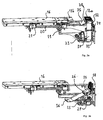
- Fig. 1 shows a trained as a laser punch press machine tool 1 , which has a conventional punch 3 and a laser processing head 4 as tools for processing a sheet serving as a workpiece 2 .
- the workpiece 2 to be machined supports during workpiece machining on a workpiece support 5 in the form of a machining table.
- a conventional holding device 6 which has clamps 7 for holding the workpiece 2
- the workpiece 2 can be displaced relative to the stationary punch 3 and the laser processing head 4 in the X direction of the sheet plane (XY plane of an XYZ coordinate system).
- the workpiece 2 In the Y-direction of the sheet plane, the workpiece 2 can be moved by moving the workpiece support 5 together with the holding device 6 relative to a support 8 on which the workpiece support 5 is mounted by means of a conventional guide (not shown).
- the workpiece 2 can thus be displaced in the X- and Y-direction relative to the punch 3 and the laser processing head 4, so that the respectively to be machined portion of the workpiece 2 in a stationary processing area 9 of the punch 3 or through a substantially circular suction opening 10th in the workpiece support 5 limited processing area 11 of the laser processing head 4 can be spent.
- the partial region of the workpiece support 5 in the X direction, on which the processing regions 9, 11 are formed, is stationary in this case and is not displaced in the Y direction relative to the support 8.
- the latter is activated in order to completely cut out, for example, a rectangular workpiece part 12 from the workpiece 2.
- the workpiece part 12 rests in the plane of the sheet on two adjacent supports 13a, 13b positioned in the sheet plane in the form of flaps and on a support table 16.
- the first support 13a is arranged directly below the laser processing head 4 and has the processing region 11 defining suction opening 10.
- the supports 13a, 13b can be pivoted on opposite sides 14a, 14b about two parallel axes of rotation 15a, 15b .
- the axes of rotation 15a, 15b are in this case arranged at a distance which is twice the width (2 b ) of the two supports 13a, 13b in the Y direction.
- the workpiece part 12, the dimension of which is dimensioned larger in the Y direction than this distance can be at the in Fig. 1 shown positioning of the supports 13a, 13b are not spent in the discharge position, without this rotates about its own axis, which would result in a too slow discharge of the workpiece part 12.
- the second support 13b is fastened to the support table 16 and can be moved together with it in the Y-direction, i. horizontally, to be moved in the sheet plane.
- This increases the distance between the two axes of rotation 15a, 15b in the Y direction and between the two supports 13a, 13b, a through opening (not shown) in the workpiece support 5 is formed.
- the support table 16 is displaced in this case until the workpiece part 12 rests only at its opposite ends on the upper sides of the two supports 13a, 13b and no longer on the support table 16 itself.
- FIGS. 2a -d The process of discharging the workpiece part 12 from the in Fig. 1 shown position W1 , in which the workpiece part 12 is located in the plane of the workpiece support 5, in an underlying discharge position W2 will be described below from FIGS. 2a -d explained in more detail.
- the workpiece part 12 is mounted both on the upper side of the first support 13a, which forms a first opening delimitation 17a together with a stationary part of the workpiece support 5a , as well as on the upper side of the second support 13b and the support table 16, which together form a second opening delimitation 17b ,
- the two opening delimitations 17a, 17b form two parts of a discharge device 17 for discharging the workpiece part 12.
- the opening delimitations 17a, 17b are located in Fig. 2a in a position where the two pads 13a, 13b are adjacent to each other.
- the workpiece part 12 rests on the support table 16 and can not be discharged vertically downwards without being displaced in the sheet plane.
- the second opening delimitation 17b is therefore moved in the horizontal direction along the inward direction Fig. 2a is moved by moving the support table in this direction until the second opening limit 17b with the edge of the second support 13b has reached a position A1 in which the workpiece part 12 no longer rests on the support table 16, as in FIG Fig. 2b is shown.
- the position A1 of the second opening limit 17b depends both on the position of the workpiece part 12 relative to the supports 13a, 13b and on the maximum dimension L1 of the workpiece part 12 in the horizontal direction Y. Since the position of that end of the workpiece part 12, which rests on the stationary opening delimitation 17a, corresponds to the position of the processing area 10 after the final free cutting, the discharge position A1 is essentially determined by the maximum dimension L1 of the workpiece part 12 in the horizontal direction and is selected so that that just a discharge of the workpiece part 12 by the double amount 2b of the width of the pads 13a, 13b extended passage D1 can be done.
- a further position A2 of the second opening delimitation 17b is shown in dash-dotted lines, in which a further passage opening D2 is formed whose width is greater than that of the passage opening D1.
- a workpiece part 12 with a larger maximum dimension L2 can be discharged through the through opening D2 extended by twice the amount 2b of the width of the supports 13a, 13b.
- the displacement of the opening delimitations 17a, 17b is calculated as a function of the maximum dimensions L1 and L2 of the workpiece part 12 of the NC control of the machine tool 1 and the support table 16 moves controlled accordingly. It is understood that as an alternative to in Fig. 2a, b shown moving the opening delimitations 17a, 17b after the free cutting of the workpiece part 12 from the workpiece 2, the positions A1, A2 can also be taken before the workpiece part 12 cut from the workpiece 2.
- the two supports 13a, 13b are accelerated from its horizontal position in the sheet plane out with an acceleration in the negative Z direction linearly downwards, which is three times the corresponds to the workpiece part 12 acting gravitational acceleration.
- the supports 13a, 13b By the linear movement of the supports 13a, 13b down over a distance d of about 3 mm in this case the workpiece part 12 is lifted from the supports 13a, 13b, as in Fig. 2c is shown.
- the two supports 13a, 13b pivoted about their respective axes of rotation 15a, 15b, as indicated by arrows in Fig.
- the workpiece part 12 initially on the top of the pads 13a, 13b stored by means of a linear movement by a distance of eg a few millimeters are moved to a position located below the sheet plane to avoid hooking of the workpiece part (not shown) remaining workpiece , From this lowered position out of the above movement can then be performed.
- the supports 13a, 13b they can be moved in other ways from the movement path 18 of the workpiece part 12, for example in a linear movement perpendicular to the direction of gravity, for example by the support table 16 is displaced in the horizontal direction, whereby also the passage opening D1 is extended.
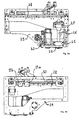
- FIGS. 3a , b respectively detail views of a lower part of the machine tool 1 of Fig. 1 show how the in FIGS. 2a, b described sequence of movements can be realized structurally.
- the support table 16 with a in Fig. 3a shown spindle drive as a movement unit in connection, which has an electric motor 19 and a threaded spindle 20 which extends in the direction of the opening movement (Y-direction).
- the threaded spindle 20 and the electric motor 19 are offset below the plane of the sheet to the support table 16 in the X direction and arranged adjacent thereto.
- a spindle nut 21 attached to the support table 16 is guided in the threaded spindle 20 and serves for the continuous movement of the support table 16 in the horizontal direction.
- the movement path of the spindle nut 21 along the Y direction is via a (in Fig. 1 shown) control unit 22 of the machine tool 1 controlled.
- the control unit 22 also serves to control the movement of the workpiece 2 and the punch 3 and the laser processing head 4 during execution of a
- the control unit 22 also serves to control the displacement of the support table 16 by the current flow through the electric motor 19 in response to the maximum dimension L1, L2 of the workpiece part 12 is controlled.
- the Ausschleusposition A2 along the horizontal direction Y is continuously controllable.
- FIG. 4a, b shown further movement unit provided, which has a further electric motor 23 as a drive, which is coupled via a toothed belt 24 with a guided in an overload-safe bearing 25 , extending in the vertical direction threaded spindle 26 .
- the vertical threaded spindle 26 of the further movement unit has a further spindle nut 27 , which can be moved in and against the direction of gravity (negative Z direction).
- the spindle nut 27 is attached to a guide plate 28 , which in turn is guided in a longitudinal plate 29 in and against the direction of gravity linearly displaceable.
- the guide plate 28 has a horizontally extending guide rail 30 , in which two connecting pieces 31a, 31b are guided linearly displaceable.
- the connecting pieces 31a, 31b respectively engage the supports 13a, 13b in an eccentric manner with respect to the axes of rotation 15a, 15b and are rotatably mounted thereon, while being non-rotatably guided along the guide rail 30. If the spindle nut 27 is moved by means of the drive 23 down, the guide plate 28 lowers and guided on the guide rail 30 connecting pieces 31a, 31 b are taken. During this movement, the connecting pieces 31a, 31b are displaced horizontally along the guide rail 30 due to the non-rotatable mounting.
- the guide rail 30 in this case has a length which allows the second connecting piece 31b during the movement of the second Opening limit 17b in the horizontal direction in the in Fig. 3a, b take shown position.
- the axis of rotation 15a is rotatably mounted on a support plate 32 extending in a vertical, ie in the direction of gravity.
- the support plate 32 is guided on a further, also in the direction of gravity extending plate 33 of a (not shown) transverse frame and biased by applying a force against the direction of gravity by means of a stop unit 34 having a (not shown) spring unit as a shock absorber and a (not shown) Having hydraulic piston.
- the support plate 32 and thus the bearing of the rotation axis 15a is pressed by the force applied by the connecting pieces 31 a, 31 b against the direction of gravity force against the force acting in the direction of gravity spring or hydraulic force upwards, typically with a stroke of approx. 3-5 mm.
- the storage of the second edition 13b on the support table 16 is designed accordingly.
- a chute 35 is attached to the first connector 31 a.
- the chute 35 is taken down and protrudes in the opening position of the supports 13a, 13b in the (not shown) movement path of the workpiece part.
- the connecting piece 31 a mounted chute 35 includes in the opening position of the pads 13 a, 13 b directly to a fixed chute 36 at.
- a free-falling workpiece part thus meets at its discharge position either on the fixed chute 36 or on the first connector 31 a fixed, hereinafter referred to as movable chute 35 and can be removed in a sliding movement of the working area of the machine tool 1.
- the movable chute 35 provided in addition to the fixed chute 36 is required to provide an in Fig. 3a shown suction tube 37 , which in the in Fig. 3a shown horizontal position of the first support 13a with the suction opening 10 of the first support 13a is in communication.
- the suction tube 37 is at the in Fig. 3b attached spindle nut 27 is fixed and is taken along with their displacement in the direction of gravity down.
- An end piece 38 of the suction tube 37 is attached to the first support 13a and is pivoted therewith, as shown in Fig. 3c.
- a (not shown) beam catcher is provided at the lower end thereof to intercept the laser beam passing through the suction opening 10 in the laser mode.
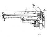
- machine tool 1 may follow the machining of the workpiece 2 with the laser processing head 3 at the processing position 11, a machining of the workpiece 2 at the adjacent processing position 9 of the punch 3.
- the opening delimitations 17a, 17b can be moved from the position shown in FIG. 3c into a closed position, which in FIG Fig. 5 is shown.
- the opening delimitations 17a, 17b completely close an opening in the workpiece support 5 and the supports 13a, 13b abut one another on their upper sides in their downwardly pivoted position.
- the supports 13a, 13b are protected from chips generated during machining of the workpiece 2 at the processing position 9 of the punch 3.
- a partial area 16a of the support table 16 the width of which corresponds approximately to the width 2b of the supports 13a, 13b, completely covers the area which is in Fig. 1 was taken from the pads 13a, 13b.
- the punch 3 may additionally serve as a fixing unit for a workpiece part in the movement of the second opening limit 17b by this during the opening movement in engagement in a attached to the processing position 9 on the workpiece support 5
- the punch 3 may additionally serve as a fixing unit for a workpiece part in the movement of the second opening limit 17b by this during the opening movement in engagement in a attached to the processing position 9 on the workpiece support 5
- a discharge in the manner described above can also be advantageously carried out on other machine tools, for example on punching and bending machines, in which the workpiece parts are still bent after cutting free further processed before they are discharged from the machine tool. Also in this case, the discharging can be accelerated by the variable positions of the opening boundaries depending on the individual dimensions of the respective workpiece part expertiseschleusenden and thus downtime during processing can be reduced.
Landscapes
- Engineering & Computer Science (AREA)
- Mechanical Engineering (AREA)
- Laser Beam Processing (AREA)
- Turning (AREA)
- Electrical Discharge Machining, Electrochemical Machining, And Combined Machining (AREA)
Claims (14)
- Machine-outil (1) dévolue à l'usinage, par sectionnement, de pièces à usiner (2) revêtant de préférence la forme de plaques, en particulier des tôles, comprenant un support (5) de pièces et un système d'évacuation (17) prévu sur ledit support (5) de pièces, pour l'évacuation de parties de pièces (12) obtenues en tant que produits de l'usinage par sectionnement, ledit système d'évacuation (17) comportant deux délimitations d'orifices (17a, 17b) qui, en vue de former un orifice de passage dédié à l'évacuation de parties de pièces (12), peuvent être déplacées l'une vis-à-vis de l'autre par coulissement mutuel dans la direction horizontale (Y), sachant que lesdites délimitations d'orifices (17a, 17b) peuvent être présentées à différents emplacements (A1, A2) par coulissement réciproque dans la direction horizontale, en formant des orifices de passage (D1, D2) différemment larges, dédiés à l'évacuation de parties de pièces (12),
caractérisée par le fait que
des délimitations d'orifices (17a, 17b) offrent chacune exactement un appui (13a, 13b), au moins un appui (13a, 13b) étant monté avec faculté de pivotement vers le bas autour d'un axe de rotation (15a , 15b) s'étendant, de préférence, perpendiculairement à la direction horizontale (Y), de façon à élargir l'orifice de passage (d1, d2), lesdits appuis (13a, 13b) pouvant être abaissés de manière accélérée, par un mouvement linéaire effectué dans la direction de la gravité (Z), lequel mouvement linéaire s'opère, de préférence, sur une course de 10 mm au maximum, notamment de 8 mm au maximum. - Machine-outil selon la revendication 1, caractérisée par une unité de commande (22) destinée à commander l'emplacement (A1, A2) des délimitations d'orifices (17a, 17b) en fonction d'une cote maximale (L1, L2) dans la direction horizontale (Y) de la partie de pièce (12) produite au cours de l'usinage par sectionnement.
- Machine-outil selon la revendication 1 ou 2, caractérisée par une unité (19, 20) de mise en mouvement conçue pour imprimer, à au moins l'une des délimitations d'orifices (17a, 17b), un mouvement continu télécommandé dans la direction horizontale (Y).
- Machine-outil selon la revendication 3, caractérisée par le fait que l'unité (19, 20) de mise en mouvement présente un entraînement par broche en vue d'imprimer, à au moins l'une (17b) des délimitations d'orifices, un mouvement continu dans la direction horizontale (Y).
- Machine-outil selon l'une des revendications précédentes, caractérisée par un système de mesure conçu pour déterminer le trajet parcouru par les délimitations d'orifices (17a, 17b) dans la direction horizontale (Y).
- Machine-outil selon l'une des revendications précédentes, caractérisée par le fait qu'au moins un appui (13b) est fixé à un plateau d'appui (16) pouvant coulisser dans la direction horizontale (Y), et sur lequel ledit appui (13b) est monté à rotation.
- Machine-outil selon l'une des revendications précédentes, caractérisée par le fait qu'au moins une délimitation d'orifices (17b) comporte un plateau d'appui (16) apte à coulisser dans la direction horizontale (Y) et pouvant être abaissé de manière accélérée, de préférence à au moins une extrémité tournée vers l'orifice de passage, par un mouvement linéaire effectué dans la direction de la gravité (Z), lequel mouvement linéaire s'opère, de préférence, sur une course de 10 mm au maximum, notamment de 8 mm au maximum.
- Machine-outil selon l'une des revendications précédentes, caractérisée par le fait que les délimitations d'orifices (17a, 17b) peuvent être animées de mouvements relatifs, dans la direction horizontale (Y), jusqu'à un emplacement de fermeture (A3) auquel lesdites délimitations d'orifices (17a, 17b) obturent intégralement un orifice pratiqué dans le support (5) de pièces ; et les appuis (13a, 13b) sont, de préférence, au moins partiellement en applique mutuelle, par leurs faces supérieures, à l'état résultant d'un pivotement vers le bas.
- Machine-outil selon l'une des revendications précédentes, caractérisée par le fait que l'une (17a) des deux délimitations d'orifices occupe une position stationnaire dans la direction horizontale (Y).
- Machine-outil selon la revendication 9, caractérisée par le fait que ladite machine-outil est équipée d'un système d'assujettissement (3) affecté à la consignation à demeure de la partie de pièce (12), sur la délimitation d'orifices (17a) stationnaire, lors du mouvement relatif des délimitations d'orifices (17a, 17b) dans la direction horizontale (Y).
- Machine-outil selon l'une des revendications précédentes, caractérisée par le fait qu'un couloir rigide (36) est disposé dans l'orifice de passage (D1, D2), au- dessous des délimitations d'orifices (17a, 17b), en vue de l'évacuation de la partie de pièce (12).
- Procédé d'évacuation de parties de pièces (12), obtenues en tant que produits d'un usinage de pièces par sectionnement, sur une machine-outil (1) dévolue à l'usinage par sectionnement de pièces à usiner (2) revêtant de préférence la forme de plaques, en particulier des tôles, au moyen d'un système d'évacuation (17) comportant deux délimitations d'orifices (17a, 17b) qui, en vue de former un orifice de passage dédié à l'évacuation de parties de pièces (12), sont déplacées l'une vis-à-vis de l'autre par coulissement mutuel dans la direction horizontale (Y), sachant que lesdites délimitations d'orifices (17a, 17b) sont présentées à différents emplacements (A1, A2) par coulissement réciproque dans la direction horizontale, en formant des orifices de passage (D1, D2) différemment larges, dédiés à l'évacuation de parties de pièces (12),
caractérisé par le fait que
les délimitations d'orifices (17a, 17b) offrent des appuis (13a, 13b), au moins un appui (13a, 13b) étant animé de pivotements vers le bas autour d'un axe de rotation (15a , 15b) s'étendant, de préférence, perpendiculairement à la direction horizontale (Y), de façon à élargir l'orifice de passage (d1, d2), lesdits appuis (13a, 13b) pouvant être abaissés de manière accélérée, par un mouvement linéaire effectué dans la direction de la gravité (Z), lequel mouvement linéaire s'opère, de préférence, sur une course de 10 mm au maximum, notamment de 8 mm au maximum. - Procédé selon la revendication 12, caractérisé par le fait que l'emplacement (A1, A2) des délimitations d'orifices (17a, 17b) est commandé en fonction d'une cote maximale (L1, L2) dans la direction horizontale (Y) de la partie de pièce (12) produite au cours de l'usinage par sectionnement.
- Procédé selon la revendication 12 ou 13, caractérisé par le fait qu'au moins l'une des délimitations d'orifices (17a, 17b) est animée, dans la direction horizontale (Y), d'un mouvement s'opérant en mode continu et télécommandé.
Priority Applications (6)
| Application Number | Priority Date | Filing Date | Title |
|---|---|---|---|
| PL07012867T PL2008736T3 (pl) | 2007-06-30 | 2007-06-30 | Obrabiarka i sposób wyrzucania części przedmiotu obrabianego |
| AT07012867T ATE517705T1 (de) | 2007-06-30 | 2007-06-30 | Werkzeugmaschine und verfahren zum ausschleusen eines werkstückteils |
| EP20070012867 EP2008736B1 (fr) | 2007-06-30 | 2007-06-30 | Machine-outil et procédé destinés à l'évacuation d'une partie d'une pièce à usiner |
| DE200720018546 DE202007018546U1 (de) | 2007-06-30 | 2007-06-30 | Werkzeugmaschine zum trennenden Bearbeiten von Werkstücken |
| CNU2008201139948U CN201346719Y (zh) | 2007-06-30 | 2008-06-30 | 用于分离加工工件的机床 |
| US12/164,386 US8618433B2 (en) | 2007-06-30 | 2008-06-30 | Workpiece part discharge system |
Applications Claiming Priority (1)
| Application Number | Priority Date | Filing Date | Title |
|---|---|---|---|
| EP20070012867 EP2008736B1 (fr) | 2007-06-30 | 2007-06-30 | Machine-outil et procédé destinés à l'évacuation d'une partie d'une pièce à usiner |
Publications (2)
| Publication Number | Publication Date |
|---|---|
| EP2008736A1 EP2008736A1 (fr) | 2008-12-31 |
| EP2008736B1 true EP2008736B1 (fr) | 2011-07-27 |
Family
ID=38694884
Family Applications (1)
| Application Number | Title | Priority Date | Filing Date |
|---|---|---|---|
| EP20070012867 Active EP2008736B1 (fr) | 2007-06-30 | 2007-06-30 | Machine-outil et procédé destinés à l'évacuation d'une partie d'une pièce à usiner |
Country Status (5)
| Country | Link |
|---|---|
| US (1) | US8618433B2 (fr) |
| EP (1) | EP2008736B1 (fr) |
| CN (1) | CN201346719Y (fr) |
| AT (1) | ATE517705T1 (fr) |
| PL (1) | PL2008736T3 (fr) |
Families Citing this family (12)
| Publication number | Priority date | Publication date | Assignee | Title |
|---|---|---|---|---|
| US8251471B2 (en) * | 2003-08-18 | 2012-08-28 | Fujifilm Dimatix, Inc. | Individual jet voltage trimming circuitry |
| US7556327B2 (en) * | 2004-11-05 | 2009-07-07 | Fujifilm Dimatix, Inc. | Charge leakage prevention for inkjet printing |
| ATE507910T1 (de) * | 2007-06-30 | 2011-05-15 | Trumpf Werkzeugmaschinen Gmbh | Werkzeugmaschine und verfahren zum verbringen eines werkstückteils aus einer auflageposition in eine abfuhrposition |
| EP2359952B1 (fr) * | 2010-07-09 | 2012-09-12 | TRUMPF Werkzeugmaschinen GmbH + Co. KG | Dispositif et procédé d'évacuation de produits de traitement différentiés sur une machine-outil |
| DE102012207818A1 (de) * | 2012-05-10 | 2013-11-14 | Trumpf Sachsen Gmbh | Verfahren und Vorrichtung zum Trennen von Bearbeitungsprodukten an einer Werkzeugmaschine |
| DE102013226821B4 (de) | 2013-12-20 | 2020-09-03 | Trumpf Werkzeugmaschinen Gmbh + Co. Kg | Maschine zum trennenden Bearbeiten von plattenförmigen Werkstücken, Verfahren zum trennenden Bearbeiten eines Werkstücks und Computerprogrammprodukt |
| DE102013226816A1 (de) | 2013-12-20 | 2015-06-25 | Trumpf Werkzeugmaschinen Gmbh + Co. Kg | Maschine zum trennenden Bearbeiten von plattenförmigen Werkstücken |
| DE102013226818B4 (de) * | 2013-12-20 | 2015-07-30 | Trumpf Werkzeugmaschinen Gmbh + Co. Kg | Maschine zum trennenden Bearbeiten von plattenförmigen Werkstücken |
| DE102015204562A1 (de) | 2015-03-13 | 2016-09-15 | Trumpf Werkzeugmaschinen Gmbh + Co. Kg | Maschine zum trennenden Bearbeiten von plattenförmigen Werkstücken |
| DE102016208872A1 (de) * | 2016-05-23 | 2017-11-23 | Trumpf Werkzeugmaschinen Gmbh + Co. Kg | Maschine zum trennenden Bearbeiten eines plattenförmigen Werkstücks und Verfahren zum Ausdrücken eines freigetrennten Werkstückteils |
| EP3915707A1 (fr) | 2020-05-28 | 2021-12-01 | TRUMPF Werkzeugmaschinen GmbH + Co. KG | Procédé de fabrication de parties de pièce à partir d'une pièce en forme de plaque, ainsi que programme de traitement des données et machine d'usinage destinée à leur fabrication |
| CN117055301A (zh) * | 2021-07-30 | 2023-11-14 | 迪盛(武汉)微电子科技有限公司 | 工作平台的上下料方法 |
Family Cites Families (47)
| Publication number | Priority date | Publication date | Assignee | Title |
|---|---|---|---|---|
| US2824610A (en) * | 1952-08-23 | 1958-02-25 | Schubert | Mat segregating mechanism and methods |
| US2796128A (en) * | 1954-09-07 | 1957-06-18 | Western Electric Co | Method of detecting a plugged condition of a die |
| US3375744A (en) * | 1966-03-08 | 1968-04-02 | Eastman Kodak Co | Cutting, counting and classifying apparatus |
| US3772948A (en) * | 1970-06-05 | 1973-11-20 | Burton Noonan | Method and apparatus for forming cloth lengths with folded hems |
| CH654777A5 (fr) * | 1983-07-27 | 1986-03-14 | Charmilles Sa Ateliers | Machine pour decouper par electro-erosion. |
| CH660857A5 (fr) * | 1984-10-16 | 1987-05-29 | Charmilles Technologies | Procede pour controler la forme d'une surface usinee par un fil a eroder et dispositif pour sa mise en oeuvre. |
| JPS61295967A (ja) * | 1985-06-21 | 1986-12-26 | Suzuki:Kk | スタツカ装置 |
| JPS6343730A (ja) * | 1986-08-09 | 1988-02-24 | Murata Mach Ltd | 打抜き加工方法および打抜き加工装置 |
| US5088363A (en) * | 1987-08-21 | 1992-02-18 | Aaron U. Jones | Method and apparatus for an automatic sawmill |
| DE3736868A1 (de) * | 1987-10-30 | 1989-05-11 | Benz & Hilgers Gmbh | Stapelvorrichtung an verpackungsmaschinen fuer beutel od. dgl. |
| JPH0297524U (fr) * | 1988-08-31 | 1990-08-03 | ||
| JP2970883B2 (ja) * | 1991-04-02 | 1999-11-02 | 株式会社ソディック | ワイヤ放電加工機 |
| JPH05192725A (ja) * | 1992-01-20 | 1993-08-03 | Shiroyama Sangyo Kk | プレス機のワーク取出装置 |
| FR2695057B1 (fr) * | 1992-09-01 | 1994-11-18 | Lectra Systemes Sa | Dispositif d'aspiration pour machine de coupe automatique et procédé de découpe mettant en Óoeuvre ledit dispositif. |
| JP2921727B2 (ja) * | 1994-01-27 | 1999-07-19 | 株式会社アマダ | レーザ加工装置 |
| US5687205A (en) * | 1995-09-15 | 1997-11-11 | General Electric Company | Underwater remote drilling tool and methods |
| JPH10216860A (ja) * | 1997-02-07 | 1998-08-18 | Amada Co Ltd | レーザ・パンチ複合機におけるスクラップ排出装置 |
| DE19739059A1 (de) * | 1997-09-07 | 1999-03-11 | 3R Syst Int Ab | Halteplatte für ein Werkstück |
| DE19981060T1 (de) * | 1998-05-13 | 2000-08-03 | Mitsubishi Electric Corp | Elektrode für eine Entladungsoberflächenbehandlung, Herstellungsverfahren dafür, Entladungsoberflächenbehandlungsverfahren und Vorrichtung dafür |
| JP4004666B2 (ja) * | 1998-10-12 | 2007-11-07 | 株式会社ソディック | ワイヤカット放電加工機 |
| US6339203B1 (en) * | 1998-10-27 | 2002-01-15 | Sodick Co., Ltd. | Spindle system for diesink type electric discharge machine |
| DE19932645C5 (de) * | 1999-07-13 | 2007-01-11 | Agie S.A., Losone | Funkenerosionsmaschine und Modulsatz für den Zusammenbau von Werkzeugmaschinen, insbesondere Funkenerosionsmaschinen |
| JP2002059329A (ja) * | 2000-08-23 | 2002-02-26 | Sankyo Mfg Co Ltd | 工具マガジン |
| EP1803519A3 (fr) * | 2000-12-25 | 2007-10-10 | Fanuc Ltd | Dispositif derégulation pour machine d'usinage par électroérosion par fil. |
| JP3968461B2 (ja) * | 2001-10-09 | 2007-08-29 | 株式会社アマダ | ワークシュータ装置及び製品加工・搬出方法 |
| JP3968462B2 (ja) * | 2002-02-20 | 2007-08-29 | 株式会社アマダ | ワークシュータ装置及び製品・スクラップ搬出方法 |
| US6739244B1 (en) * | 2002-03-19 | 2004-05-25 | Prestocraft Co. | Punch and emboss tool with interchangeable dies |
| US7038158B2 (en) * | 2002-08-30 | 2006-05-02 | Mitsubishi Denki Kabushiki Kaisha | Wire electrical discharge machining apparatus |
| JP2004142027A (ja) * | 2002-10-24 | 2004-05-20 | Fanuc Ltd | ワイヤ放電加工機 |
| JP2004330329A (ja) * | 2003-05-02 | 2004-11-25 | Fanuc Ltd | ワイヤ放電加工機 |
| JP4334481B2 (ja) * | 2003-05-20 | 2009-09-30 | 三菱電機株式会社 | 放電加工装置 |
| JP2005153128A (ja) * | 2003-11-28 | 2005-06-16 | Fanuc Ltd | ワイヤ放電加工機における手動送り装置 |
| US7518081B2 (en) * | 2004-01-23 | 2009-04-14 | Mitsubishi Denki Kabushiki Kaisha | Electric discharge machining apparatus |
| JP2005211990A (ja) * | 2004-01-27 | 2005-08-11 | Fanuc Ltd | ワイヤカット放電加工装置 |
| JP4740842B2 (ja) * | 2004-03-26 | 2011-08-03 | 株式会社牧野フライス製作所 | 切削加工方法及び装置 |
| US6998562B2 (en) * | 2004-06-02 | 2006-02-14 | Fanuc Ltd | Controller for a wire electrical discharge machine |
| JP4008435B2 (ja) * | 2004-06-29 | 2007-11-14 | ファナック株式会社 | ワイヤ放電加工機のワイヤ切断装置 |
| JP4015148B2 (ja) * | 2004-10-28 | 2007-11-28 | ファナック株式会社 | ワイヤ放電加工機の制御装置 |
| JP2006159396A (ja) * | 2004-11-15 | 2006-06-22 | Fanuc Ltd | ワイヤ放電加工機及びワイヤ放電加工方法 |
| TWI277846B (en) * | 2004-12-23 | 2007-04-01 | Ind Tech Res Inst | Method of 3D electric discharge machining and program generating apparatus therefor |
| US6979795B1 (en) * | 2005-03-18 | 2005-12-27 | Sodick Co., Ltd. | Sinker electric discharge machine jump control device |
| JP4072548B2 (ja) * | 2005-09-26 | 2008-04-09 | ファナック株式会社 | ワイヤ放電加工機 |
| US7654183B2 (en) * | 2006-01-23 | 2010-02-02 | Worktools, Inc. | Compact heavy duty hole punch |
| JP4077844B2 (ja) * | 2006-02-14 | 2008-04-23 | ファナック株式会社 | 制動装置を備えた工作機械 |
| JP5026027B2 (ja) * | 2006-08-29 | 2012-09-12 | ヤマザキマザック株式会社 | レーザ加工機の自動工具交換装置 |
| EP2352381A4 (fr) * | 2008-11-10 | 2012-04-04 | Ross Ind Inc | Appareil et procédé de tranchage efficace et sans salissure de viandes, de volailles et de produits alimentaires similaires |
| DE202011111071U1 (de) * | 2010-05-01 | 2019-03-20 | Formax, Inc. | Hochgeschwindigkeitsschneidmaschine |
-
2007
- 2007-06-30 PL PL07012867T patent/PL2008736T3/pl unknown
- 2007-06-30 AT AT07012867T patent/ATE517705T1/de active
- 2007-06-30 EP EP20070012867 patent/EP2008736B1/fr active Active
-
2008
- 2008-06-30 CN CNU2008201139948U patent/CN201346719Y/zh not_active Expired - Lifetime
- 2008-06-30 US US12/164,386 patent/US8618433B2/en active Active
Also Published As
| Publication number | Publication date |
|---|---|
| ATE517705T1 (de) | 2011-08-15 |
| CN201346719Y (zh) | 2009-11-18 |
| US8618433B2 (en) | 2013-12-31 |
| US20090010731A1 (en) | 2009-01-08 |
| PL2008736T3 (pl) | 2011-11-30 |
| EP2008736A1 (fr) | 2008-12-31 |
Similar Documents
| Publication | Publication Date | Title |
|---|---|---|
| EP2008736B1 (fr) | Machine-outil et procédé destinés à l'évacuation d'une partie d'une pièce à usiner | |
| EP2022601B1 (fr) | Machine de traitement laser destinée au traitement de pièces à usiner tout comme procédé mécanique destiné au fonctionnement de pièces à usiner à l'aide d'un faisceau laser | |
| EP3463734A1 (fr) | Machine pour séparer par usinage une pièce sous forme de plaque et procédé pour éjecter une partie de pièce dégagée par découpe | |
| EP2420344A1 (fr) | Procédé et dispositif de découpe d'un contour dans une bande de tôle | |
| DE1777355B2 (de) | Transporteinrichtung zum Transportieren von Werkstücken zwischen zwei Pressen | |
| EP3219429B1 (fr) | Machine-outil équipée d'un dispositif d'estampage et d'un dispositif d'usinage laser et procédé d'usinage de pièces à l'aide d'une telle machine-outil | |
| EP3515626B1 (fr) | Machine-outil et procédé d'usinage de pièces en forme de plaque | |
| EP3515624A1 (fr) | Procédé, machine-outil et outil de découpage pour le découpage continu à course multiple de pièces en forme de plaque | |
| EP3052256A1 (fr) | Presse à plier et procédé de pliage | |
| EP3515622B1 (fr) | Outil et machine-outil, ainsi que procédé de découpe et/ou de formage de pièces en forme de plaque | |
| DE3539852A1 (de) | Mechanische schweisspresse | |
| WO2018055183A1 (fr) | Outil et machine-outil et procédé de traitement de pièces en forme de plaques | |
| WO2018055184A1 (fr) | Outil et machine-outil ainsi que procédé d'usinage de pièces en forme de plaque, en particulier de tôles | |
| EP3515617B1 (fr) | Outil et machine-outil ainsi que procédé d'usinage de pièces en forme de plaque | |
| DE102016119435A1 (de) | Werkzeug und Werkzeugmaschine sowie Verfahren zum Bearbeiten von plattenförmigen Werkstücken | |
| EP0585576B1 (fr) | Machine à poinçonner | |
| WO2018055178A1 (fr) | Procédé et machine-outil servant à l'usinage de pièces en forme de plaque, en particulier de tôles | |
| DE102016120139B4 (de) | Verfahren, Werkzeugmaschine und Schlitzwerkzeug zum mehrhubig fortschreitenden Schlitzen von plattenförmigen Werkstücken | |
| DE202007018546U1 (de) | Werkzeugmaschine zum trennenden Bearbeiten von Werkstücken | |
| DE102016119464B4 (de) | Werkzeug und Werkzeugmaschine sowie Verfahren zur Bearbeitung von plattenförmigen Werkstücken | |
| DE102016120151A1 (de) | Verfahren und Werkzeugmaschine zum Bearbeiten von plattenförmigen Werkstücken, insbesondere von Blechen | |
| DE102016119457A1 (de) | Werkzeug und Werkzeugmaschine sowie Verfahren zur Bearbeitung von plattenförmigen Werkstücken | |
| WO2021013810A1 (fr) | Outil et procédé pour l'usinage de pièces en forme de plaques, en particulier de tôles | |
| WO2021013806A1 (fr) | Outil et procédé pour l'usinage de pièces sous forme de plaques | |
| EP4003677B1 (fr) | Entraînement oscillant de machine |
Legal Events
| Date | Code | Title | Description |
|---|---|---|---|
| PUAI | Public reference made under article 153(3) epc to a published international application that has entered the european phase |
Free format text: ORIGINAL CODE: 0009012 |
|
| AK | Designated contracting states |
Kind code of ref document: A1 Designated state(s): AT BE BG CH CY CZ DE DK EE ES FI FR GB GR HU IE IS IT LI LT LU LV MC MT NL PL PT RO SE SI SK TR |
|
| AX | Request for extension of the european patent |
Extension state: AL BA HR MK RS |
|
| 17P | Request for examination filed |
Effective date: 20081222 |
|
| 17Q | First examination report despatched |
Effective date: 20090210 |
|
| AKX | Designation fees paid |
Designated state(s): AT BE BG CH CY CZ DE DK EE ES FI FR GB GR HU IE IS IT LI LT LU LV MC MT NL PL PT RO SE SI SK TR |
|
| GRAP | Despatch of communication of intention to grant a patent |
Free format text: ORIGINAL CODE: EPIDOSNIGR1 |
|
| GRAS | Grant fee paid |
Free format text: ORIGINAL CODE: EPIDOSNIGR3 |
|
| GRAA | (expected) grant |
Free format text: ORIGINAL CODE: 0009210 |
|
| AK | Designated contracting states |
Kind code of ref document: B1 Designated state(s): AT BE BG CH CY CZ DE DK EE ES FI FR GB GR HU IE IS IT LI LT LU LV MC MT NL PL PT RO SE SI SK TR |
|
| REG | Reference to a national code |
Ref country code: GB Ref legal event code: FG4D Free format text: NOT ENGLISH |
|
| REG | Reference to a national code |
Ref country code: CH Ref legal event code: EP |
|
| REG | Reference to a national code |
Ref country code: DE Ref legal event code: R096 Ref document number: 502007007760 Country of ref document: DE Effective date: 20110915 |
|
| REG | Reference to a national code |
Ref country code: NL Ref legal event code: VDEP Effective date: 20110727 |
|
| REG | Reference to a national code |
Ref country code: PL Ref legal event code: T3 |
|
| PG25 | Lapsed in a contracting state [announced via postgrant information from national office to epo] |
Ref country code: LT Free format text: LAPSE BECAUSE OF FAILURE TO SUBMIT A TRANSLATION OF THE DESCRIPTION OR TO PAY THE FEE WITHIN THE PRESCRIBED TIME-LIMIT Effective date: 20110727 Ref country code: IS Free format text: LAPSE BECAUSE OF FAILURE TO SUBMIT A TRANSLATION OF THE DESCRIPTION OR TO PAY THE FEE WITHIN THE PRESCRIBED TIME-LIMIT Effective date: 20111127 Ref country code: NL Free format text: LAPSE BECAUSE OF FAILURE TO SUBMIT A TRANSLATION OF THE DESCRIPTION OR TO PAY THE FEE WITHIN THE PRESCRIBED TIME-LIMIT Effective date: 20110727 Ref country code: FI Free format text: LAPSE BECAUSE OF FAILURE TO SUBMIT A TRANSLATION OF THE DESCRIPTION OR TO PAY THE FEE WITHIN THE PRESCRIBED TIME-LIMIT Effective date: 20110727 Ref country code: PT Free format text: LAPSE BECAUSE OF FAILURE TO SUBMIT A TRANSLATION OF THE DESCRIPTION OR TO PAY THE FEE WITHIN THE PRESCRIBED TIME-LIMIT Effective date: 20111128 Ref country code: SE Free format text: LAPSE BECAUSE OF FAILURE TO SUBMIT A TRANSLATION OF THE DESCRIPTION OR TO PAY THE FEE WITHIN THE PRESCRIBED TIME-LIMIT Effective date: 20110727 |
|
| PG25 | Lapsed in a contracting state [announced via postgrant information from national office to epo] |
Ref country code: LV Free format text: LAPSE BECAUSE OF FAILURE TO SUBMIT A TRANSLATION OF THE DESCRIPTION OR TO PAY THE FEE WITHIN THE PRESCRIBED TIME-LIMIT Effective date: 20110727 Ref country code: SI Free format text: LAPSE BECAUSE OF FAILURE TO SUBMIT A TRANSLATION OF THE DESCRIPTION OR TO PAY THE FEE WITHIN THE PRESCRIBED TIME-LIMIT Effective date: 20110727 Ref country code: GR Free format text: LAPSE BECAUSE OF FAILURE TO SUBMIT A TRANSLATION OF THE DESCRIPTION OR TO PAY THE FEE WITHIN THE PRESCRIBED TIME-LIMIT Effective date: 20111028 Ref country code: CY Free format text: LAPSE BECAUSE OF FAILURE TO SUBMIT A TRANSLATION OF THE DESCRIPTION OR TO PAY THE FEE WITHIN THE PRESCRIBED TIME-LIMIT Effective date: 20110727 |
|
| REG | Reference to a national code |
Ref country code: IE Ref legal event code: FD4D |
|
| PG25 | Lapsed in a contracting state [announced via postgrant information from national office to epo] |
Ref country code: IE Free format text: LAPSE BECAUSE OF FAILURE TO SUBMIT A TRANSLATION OF THE DESCRIPTION OR TO PAY THE FEE WITHIN THE PRESCRIBED TIME-LIMIT Effective date: 20110727 Ref country code: SK Free format text: LAPSE BECAUSE OF FAILURE TO SUBMIT A TRANSLATION OF THE DESCRIPTION OR TO PAY THE FEE WITHIN THE PRESCRIBED TIME-LIMIT Effective date: 20110727 |
|
| PG25 | Lapsed in a contracting state [announced via postgrant information from national office to epo] |
Ref country code: EE Free format text: LAPSE BECAUSE OF FAILURE TO SUBMIT A TRANSLATION OF THE DESCRIPTION OR TO PAY THE FEE WITHIN THE PRESCRIBED TIME-LIMIT Effective date: 20110727 Ref country code: RO Free format text: LAPSE BECAUSE OF FAILURE TO SUBMIT A TRANSLATION OF THE DESCRIPTION OR TO PAY THE FEE WITHIN THE PRESCRIBED TIME-LIMIT Effective date: 20110727 |
|
| PLBE | No opposition filed within time limit |
Free format text: ORIGINAL CODE: 0009261 |
|
| STAA | Information on the status of an ep patent application or granted ep patent |
Free format text: STATUS: NO OPPOSITION FILED WITHIN TIME LIMIT |
|
| PG25 | Lapsed in a contracting state [announced via postgrant information from national office to epo] |
Ref country code: DK Free format text: LAPSE BECAUSE OF FAILURE TO SUBMIT A TRANSLATION OF THE DESCRIPTION OR TO PAY THE FEE WITHIN THE PRESCRIBED TIME-LIMIT Effective date: 20110727 |
|
| 26N | No opposition filed |
Effective date: 20120502 |
|
| REG | Reference to a national code |
Ref country code: DE Ref legal event code: R097 Ref document number: 502007007760 Country of ref document: DE Effective date: 20120502 |
|
| BERE | Be: lapsed |
Owner name: TRUMPF WERKZEUGMASCHINEN G.M.B.H. + CO. KG Effective date: 20120630 |
|
| PG25 | Lapsed in a contracting state [announced via postgrant information from national office to epo] |
Ref country code: MC Free format text: LAPSE BECAUSE OF NON-PAYMENT OF DUE FEES Effective date: 20120630 |
|
| GBPC | Gb: european patent ceased through non-payment of renewal fee |
Effective date: 20120630 |
|
| PG25 | Lapsed in a contracting state [announced via postgrant information from national office to epo] |
Ref country code: GB Free format text: LAPSE BECAUSE OF NON-PAYMENT OF DUE FEES Effective date: 20120630 Ref country code: ES Free format text: LAPSE BECAUSE OF FAILURE TO SUBMIT A TRANSLATION OF THE DESCRIPTION OR TO PAY THE FEE WITHIN THE PRESCRIBED TIME-LIMIT Effective date: 20111107 Ref country code: BE Free format text: LAPSE BECAUSE OF NON-PAYMENT OF DUE FEES Effective date: 20120630 |
|
| PG25 | Lapsed in a contracting state [announced via postgrant information from national office to epo] |
Ref country code: BG Free format text: LAPSE BECAUSE OF FAILURE TO SUBMIT A TRANSLATION OF THE DESCRIPTION OR TO PAY THE FEE WITHIN THE PRESCRIBED TIME-LIMIT Effective date: 20111027 |
|
| PG25 | Lapsed in a contracting state [announced via postgrant information from national office to epo] |
Ref country code: MT Free format text: LAPSE BECAUSE OF FAILURE TO SUBMIT A TRANSLATION OF THE DESCRIPTION OR TO PAY THE FEE WITHIN THE PRESCRIBED TIME-LIMIT Effective date: 20110727 |
|
| PG25 | Lapsed in a contracting state [announced via postgrant information from national office to epo] |
Ref country code: TR Free format text: LAPSE BECAUSE OF FAILURE TO SUBMIT A TRANSLATION OF THE DESCRIPTION OR TO PAY THE FEE WITHIN THE PRESCRIBED TIME-LIMIT Effective date: 20110727 |
|
| PG25 | Lapsed in a contracting state [announced via postgrant information from national office to epo] |
Ref country code: LU Free format text: LAPSE BECAUSE OF NON-PAYMENT OF DUE FEES Effective date: 20120630 |
|
| PG25 | Lapsed in a contracting state [announced via postgrant information from national office to epo] |
Ref country code: HU Free format text: LAPSE BECAUSE OF FAILURE TO SUBMIT A TRANSLATION OF THE DESCRIPTION OR TO PAY THE FEE WITHIN THE PRESCRIBED TIME-LIMIT Effective date: 20070630 |
|
| REG | Reference to a national code |
Ref country code: FR Ref legal event code: PLFP Year of fee payment: 10 |
|
| REG | Reference to a national code |
Ref country code: FR Ref legal event code: PLFP Year of fee payment: 11 |
|
| REG | Reference to a national code |
Ref country code: FR Ref legal event code: PLFP Year of fee payment: 12 |
|
| PGFP | Annual fee paid to national office [announced via postgrant information from national office to epo] |
Ref country code: FR Payment date: 20210622 Year of fee payment: 15 Ref country code: IT Payment date: 20210625 Year of fee payment: 15 |
|
| PGFP | Annual fee paid to national office [announced via postgrant information from national office to epo] |
Ref country code: CH Payment date: 20210618 Year of fee payment: 15 Ref country code: AT Payment date: 20210621 Year of fee payment: 15 Ref country code: PL Payment date: 20210524 Year of fee payment: 15 |
|
| PGFP | Annual fee paid to national office [announced via postgrant information from national office to epo] |
Ref country code: CZ Payment date: 20210630 Year of fee payment: 15 |
|
| PG25 | Lapsed in a contracting state [announced via postgrant information from national office to epo] |
Ref country code: CZ Free format text: LAPSE BECAUSE OF NON-PAYMENT OF DUE FEES Effective date: 20220630 |
|
| REG | Reference to a national code |
Ref country code: CH Ref legal event code: PL |
|
| REG | Reference to a national code |
Ref country code: AT Ref legal event code: MM01 Ref document number: 517705 Country of ref document: AT Kind code of ref document: T Effective date: 20220630 |
|
| PG25 | Lapsed in a contracting state [announced via postgrant information from national office to epo] |
Ref country code: LI Free format text: LAPSE BECAUSE OF NON-PAYMENT OF DUE FEES Effective date: 20220630 Ref country code: FR Free format text: LAPSE BECAUSE OF NON-PAYMENT OF DUE FEES Effective date: 20220630 Ref country code: CH Free format text: LAPSE BECAUSE OF NON-PAYMENT OF DUE FEES Effective date: 20220630 Ref country code: AT Free format text: LAPSE BECAUSE OF NON-PAYMENT OF DUE FEES Effective date: 20220630 |
|
| PG25 | Lapsed in a contracting state [announced via postgrant information from national office to epo] |
Ref country code: IT Free format text: LAPSE BECAUSE OF NON-PAYMENT OF DUE FEES Effective date: 20220630 |
|
| PG25 | Lapsed in a contracting state [announced via postgrant information from national office to epo] |
Ref country code: PL Free format text: LAPSE BECAUSE OF NON-PAYMENT OF DUE FEES Effective date: 20220630 |
|
| PGFP | Annual fee paid to national office [announced via postgrant information from national office to epo] |
Ref country code: DE Payment date: 20250618 Year of fee payment: 19 |