EP2008749B1 - Methode zum Ablängen von kontinuierlich extrudierten Rohren in vorbestimmte Längen. - Google Patents
Methode zum Ablängen von kontinuierlich extrudierten Rohren in vorbestimmte Längen. Download PDFInfo
- Publication number
- EP2008749B1 EP2008749B1 EP07425393A EP07425393A EP2008749B1 EP 2008749 B1 EP2008749 B1 EP 2008749B1 EP 07425393 A EP07425393 A EP 07425393A EP 07425393 A EP07425393 A EP 07425393A EP 2008749 B1 EP2008749 B1 EP 2008749B1
- Authority
- EP
- European Patent Office
- Prior art keywords
- tube
- advance
- cutting
- cutting plane
- length
- Prior art date
- Legal status (The legal status is an assumption and is not a legal conclusion. Google has not performed a legal analysis and makes no representation as to the accuracy of the status listed.)
- Active
Links
Images


Classifications
-
- B—PERFORMING OPERATIONS; TRANSPORTING
- B26—HAND CUTTING TOOLS; CUTTING; SEVERING
- B26D—CUTTING; DETAILS COMMON TO MACHINES FOR PERFORATING, PUNCHING, CUTTING-OUT, STAMPING-OUT OR SEVERING
- B26D1/00—Cutting through work characterised by the nature or movement of the cutting member or particular materials not otherwise provided for; Apparatus or machines therefor; Cutting members therefor
- B26D1/56—Cutting through work characterised by the nature or movement of the cutting member or particular materials not otherwise provided for; Apparatus or machines therefor; Cutting members therefor involving a cutting member which travels with the work otherwise than in the direction of the cut, i.e. flying cutter
- B26D1/60—Cutting through work characterised by the nature or movement of the cutting member or particular materials not otherwise provided for; Apparatus or machines therefor; Cutting members therefor involving a cutting member which travels with the work otherwise than in the direction of the cut, i.e. flying cutter and is mounted on a movable carriage
-
- B—PERFORMING OPERATIONS; TRANSPORTING
- B23—MACHINE TOOLS; METAL-WORKING NOT OTHERWISE PROVIDED FOR
- B23D—PLANING; SLOTTING; SHEARING; BROACHING; SAWING; FILING; SCRAPING; LIKE OPERATIONS FOR WORKING METAL BY REMOVING MATERIAL, NOT OTHERWISE PROVIDED FOR
- B23D25/00—Machines or arrangements for shearing stock while the latter is travelling otherwise than in the direction of the cut
- B23D25/02—Flying shearing machines
- B23D25/04—Flying shearing machines in which a cutting unit moves bodily with the work while cutting
-
- B—PERFORMING OPERATIONS; TRANSPORTING
- B26—HAND CUTTING TOOLS; CUTTING; SEVERING
- B26D—CUTTING; DETAILS COMMON TO MACHINES FOR PERFORATING, PUNCHING, CUTTING-OUT, STAMPING-OUT OR SEVERING
- B26D3/00—Cutting work characterised by the nature of the cut made; Apparatus therefor
- B26D3/16—Cutting rods or tubes transversely
-
- B—PERFORMING OPERATIONS; TRANSPORTING
- B23—MACHINE TOOLS; METAL-WORKING NOT OTHERWISE PROVIDED FOR
- B23D—PLANING; SLOTTING; SHEARING; BROACHING; SAWING; FILING; SCRAPING; LIKE OPERATIONS FOR WORKING METAL BY REMOVING MATERIAL, NOT OTHERWISE PROVIDED FOR
- B23D36/00—Control arrangements specially adapted for machines for shearing or similar cutting, or for sawing, stock which the latter is travelling otherwise than in the direction of the cut
- B23D36/0091—Control arrangements specially adapted for machines for shearing or similar cutting, or for sawing, stock which the latter is travelling otherwise than in the direction of the cut for machines with more than one cutting, shearing, or sawing devices
-
- B—PERFORMING OPERATIONS; TRANSPORTING
- B26—HAND CUTTING TOOLS; CUTTING; SEVERING
- B26D—CUTTING; DETAILS COMMON TO MACHINES FOR PERFORATING, PUNCHING, CUTTING-OUT, STAMPING-OUT OR SEVERING
- B26D7/00—Details of apparatus for cutting, cutting-out, stamping-out, punching, perforating, or severing by means other than cutting
- B26D7/01—Means for holding or positioning work
- B26D2007/013—Means for holding or positioning work the work being tubes, rods or logs
-
- B—PERFORMING OPERATIONS; TRANSPORTING
- B26—HAND CUTTING TOOLS; CUTTING; SEVERING
- B26D—CUTTING; DETAILS COMMON TO MACHINES FOR PERFORATING, PUNCHING, CUTTING-OUT, STAMPING-OUT OR SEVERING
- B26D3/00—Cutting work characterised by the nature of the cut made; Apparatus therefor
- B26D3/16—Cutting rods or tubes transversely
- B26D3/161—Cutting rods or tubes transversely for obtaining more than one product at a time
-
- B—PERFORMING OPERATIONS; TRANSPORTING
- B26—HAND CUTTING TOOLS; CUTTING; SEVERING
- B26D—CUTTING; DETAILS COMMON TO MACHINES FOR PERFORATING, PUNCHING, CUTTING-OUT, STAMPING-OUT OR SEVERING
- B26D5/00—Arrangements for operating and controlling machines or devices for cutting, cutting-out, stamping-out, punching, perforating, or severing by means other than cutting
- B26D5/02—Means for moving the cutting member into its operative position for cutting
-
- B—PERFORMING OPERATIONS; TRANSPORTING
- B26—HAND CUTTING TOOLS; CUTTING; SEVERING
- B26D—CUTTING; DETAILS COMMON TO MACHINES FOR PERFORATING, PUNCHING, CUTTING-OUT, STAMPING-OUT OR SEVERING
- B26D7/00—Details of apparatus for cutting, cutting-out, stamping-out, punching, perforating, or severing by means other than cutting
- B26D7/01—Means for holding or positioning work
- B26D7/02—Means for holding or positioning work with clamping means
Definitions
- the present invention relates to a method for cutting an extruded tube into segments of lesser and predetermined length.
- plastic tubes are widely used, in particular made of PVC-U (rigid polyvinyl chloride), PP (polypropylene) and PE (polyethylene).
- PVC-U rigid polyvinyl chloride
- PP polypropylene
- PE polyethylene
- the most widely used technique for joining tubes is the bellmouth with a sealing elastomeric gasket: the end of the tube is widened and provided with a seat for a gasket, in order to enable the insertion of another tube into the end, achieving a junction with fluid-dynamic tightness.
- Plastic tube production lines are extrusion lines with continuous production in which the extruded tube advances along the line at uniform velocity (extrusion velocity).
- an automatic cutting machine commanded by an electronic control unit, able to obtain tube segments with chamfered end.
- the length of the cut segments corresponds to the nominal commercial length plus a segment with sufficient length to obtain, with subsequent bellmouth making machine, with thermoforming process, the bellmouth.
- the products most on demand are short tubes, usually tubes having commercial length of up to 500 mm.
- the traditional automatic cutting machine is configured as a carriage that moves within a frame along the axis of the tube.
- a drum comprising two rings, separated by spacers, within which is obtained a cavity that is coaxial to the tube.
- the cutting tool In the drum is located the cutting tool.
- the drum is able to rotate at high velocity around the tube. Since the tube is in constant rectilinear motion, when the cut is performed the carriage must also move at the same velocity as the tube.
- two clamps positioned on the carriage at the side of the cutting assembly, close on the tube, achieving a rigid carriage-tube structure that moves at the same velocity, thereby allowing maximum cutting precision.
- the electronic control unit receives the signal that commands the execution of the cutting cycles from an electronic position measurer that, through an electro-mechanical transducer (wheel-encoder), constantly measures the velocity of the tube and the required lengths of tube to be cut.
- the carriage starts from a motionless condition and from a starting position, follows and reaches the point to be cut, synchronises to the velocity of the tube, closes the clamps and through the cutting tool performs the cutting cycle. Once the cut is completed, the clamps release the tube and the carriage returns to the starting position, awaiting another cutting command. It is evident that the higher the extrusion velocity, the greater will be the length of travel needed by the carriage to complete the work cycle. It is also evident that, for equal extrusion velocity, the shorter the lengths of tube required, the greater will be the number of cuts the machine must execute in a unit of time.
- the so-called “flying” cut technique described in the patent EP 0129515 is advantageous. This technique enables to achieve working cycles characterised by sequences of short segments alternating to a long segment.
- the carriage provided with a shearing cutter does not take as a reference the absolute stroke-start position, but the relative position on the tube where the next cut is to be executed with respect to the instantaneous position of the carriage.
- the carriage in the return stroke does not return to a stroke-start position, but when it arrives in the vicinity of the position of the tube where the next cut is to be executed, it stops "on the fly", it reverses its motion and it reaches the cutting point, it synchronises the velocity with the extrusion velocity and it carries out the cutting cycle, and so on until the end of the working stroke.
- the carriage After completing the working stroke, the carriage returns to the stroke-start position and from said position it can cut a long segment and then resume the sequence of cuts "on the fly” that produce the short segments.
- Document US A 5 224 368 illustrates a flying die apparatus having multiple heads for performing various operations (for example: cutting and/or shearing) on tube stock or other shaped stock exiting a forming machine.
- An object of the present invention is to overcome the drawbacks described above, making available a method for cutting an extruded tube into segments with a lesser and predetermined length which enables to obtain a high machining rate.
- Another object of the present invention is to make available a method for cutting an extruded tube into segments with a lesser and predetermined length which enables to obtain relatively small bulks.
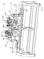
- the number 1 indicates a machine for cutting a tube extruded in continuous fashion into segments of a lesser and predetermined length.
- said machine 1 houses the tube generated by a continuous extruder positioned upstream (the extruder is not shown).
- tube means generically the set both of the cut segments, still operatively fastened to the machine 1, and of the part of tube not yet cut into segments.
- the machine 1 comprises a guide 30 that develops between a stroke-start 301 and a stroke end 302.
- the cutting machine 1 also comprises sliding means 3 that are movable along the guide 30 parallel to a direction 20 of advance of the tube along which the tube is to proceed according to a first sense of advance 21 oriented from the stroke-start 301 to the stroke end 302 of the guide 30.
- the tube moves along said first sense of advance 21 with its own velocity; said velocity is generally imposed by a suitable driving device (not shown) interposed between the cutting machine 1 and the extruder upstream.
- the machine 1 further comprises means 33 for actuating said sliding means 3 along said guide 30. Said sliding means 3, under the action of the actuating means 33, move both forward and backward along the guide 30.
- the actuating means 33 comprise a motion transmission 34 comprising a belt integral with a portion of the sliding means 3, closed in a loop on itself and wound around a pair of pulleys. Said motion transmission 34 is responsible for the reciprocating translation of the sliding means 3 along the guide 30.
- the actuating means 33 comprise a fluid-dynamic jack that actuates the sliding means 3.
- the sliding means 3 comprise a first station 31 for cutting the tube, said first cutting station 31 comprising a first shearing cutter 311 defining a first cutting plane 310 transverse to the direction 20 of advance of the tube.
- the first cutting plane 310 is orthogonal to the direction 20 of advance of the tube.
- the sliding means 3 further comprise a second station 32 for cutting the tube positioned upstream of the first cutting station 31 with respect to the first sense 21 of advance of the tube along the direction 20 of advance, said second cutting station 32 comprising a second shearing cutter 312 distanced from the first shearing cutter 311 and defining a second cutting plane 320 that is transverse to the direction 20 of advance of the tube.
- the first and the second shearing cutter 311, 312 are mutually distinct and separate.
- the second cutting plane 320 is orthogonal relative to the direction 20 of advance of the tube.
- the first and the second cutting plane 310, 320 are mutually parallel.
- the cutting action of the first and of the second shearing cutter 311, 312 can take place at least partly simultaneously, but it preferably takes place wholly simultaneously.
- shearing cutter means the portion of the corresponding cutting station which interacts physically with the tube, determining its split into two distinct, independent portions.
- This chamfer is advantageously used to facilitate the connection by insertion of two distinct segments whereof at least one has a bellmouth end.
- both the first and the second shearing cutter 311, 312 are constituted by a tool that can be a blade (see figure 7 ) or a rotating disk (see figure 8 ).
- To the shearing cutter can also be associated the portion 313 of the cutting station necessary to execute a conical chamfer.
- the sliding means 3 comprise means 50 for gripping tube portions, said gripping means 50 being positioned, relative to the first sense of advance 21 of the tube, at least upstream of the first cutting plane 310, downstream of the second cutting plane 320 and between the first and the second cutting plane 310, 320.
- the gripping means 50 are movable between a first configuration in which they securely grip corresponding tube portions and a second configuration in which they release said tube portions.
- the cutting machine 1 further comprises means for controlling the actuating means 33 and means for measuring the relative displacement between said tube and said first and second cutting plane 310, 320 along the direction of advance 20 of the tube.
- the actuating means 33 are able to synchronise with the motion of the tube the motion of each cutting station 31, 32 along the direction of advance 20, positioning the first and the second cutting plane 310, 320 at desired positions on the tube.
- the control means command the means 33 for actuating said sliding means 3 at least as a function:
- said gripping means 50 assume said first configuration to keep in position tube segments positioned at the first and at the second cutting plane 310, 320. Said second configuration is assumed after each cut to allow the relative motion of the tube and of the sliding means 3 along the direction 20 of advance of the tube.
- the relative displacement of the cutting stations 31, 32 with respect to the tube is possible.
- the action of the gripping means enables to maximise the cutting precision preventing undesired displacements between the tube and the first and/or the second shearing cutter 311,312.
- the sliding means 3 could also comprise more than two cutting stations 31, 32.
- each cutting station should be associated a corresponding cutting plane.
- shear scraps means the portion of the tube that is removed by the shearing cutter and that does not remain attached to either of the two segments generated by the cut.
- Figure 7 shows a cut without production of scraps
- figure 8 shows a cut with the production of a shear scrap by the second shearing cutter 312.
- the machine 1 comprises means for positioning the first and the second cutting plane 310, 320 at a mutual distance defined by the following formula: n ⁇ L + K where:
- the natural number n takes into account the fact that from the tube portion interposed between the first and the second cutting plane 310, 320 and obtained from the cut executed simultaneously by the first and by the second shearing cutter 311, 312, a number of segments of equal length L equal to the natural number n will be obtained.
- the value of the natural number n is greater than 1.
- the first corrective coefficient K is advantageously equal to 0.
- the thickness of the first and of the second shearing cutter 311, 312 is variable from 0 to 3 mm.
- each shearing cutter 311, 312 are associated multiple shearing planes included in an interval defined by the length of the scrap generated by the corresponding shearing cutter 311, 312 along the direction 20 of advance of the tube.
- the first and the second cutting plane 310, 320 coinciding with the two shearing planes mutually closest and generated at least in part simultaneously one by the first shearing cutter 311 and one by the second shearing cutter 312.
- the cutting planes 310, 320 are defined and as a function of the subsequent steps provided by the method implemented by the machine 1, in the formula n.L+K (previously indicated), if one wants to take into account the scrap generated by the shearing cutters 311, 312, it will be necessary to take into account only the scrap generated by the first shearing cutter 311.
- the first corrective coefficient is equal to the length of the scrap generated by the first shearing cutter 311 along the direction 20 of advance multiplied by n-1 where n is the aforesaid natural number. From this it is evident that if n is equal to 1, the first corrective coefficient K is nil.
- the cutting machine 1 further comprises a user interface to set the value of the preferential length L of the desired tube segments outputted by the machine 1.
- the preferential length L is the target length which the machine 1 is to produce.
- a number of segments of a length equal to said preferential length is usually alternated by the generation of a segment of greater dimensions. This depends both on the fact that the guide 30 has a finite development and on the operating procedures of the cutting machine 1 (as better explained below).
- the length of said segment of greater dimension can also be pre-set (e.g. to create a stock of segments of this length). These long segments are in any case usually generated in a smaller number than the segments of preferential length L and their generation constitutes a way to try to optimise the production of the machine 1.
- the machine 1 further comprises an electronic unit that enables to determine the value of the natural number n as a function of the value of the length L of the desired segments and of pre-set geometric parameters of the machine 1.
- the value of n should be the smallest possible, taking into account the maximum and minimum mutual distance whereat it is possible to position the first and the second cutting plane 310, 320. This is linked to the need to contain the length of the stroke which the sliding means 3 must have available.
- the maximum and minimum mutual distance whereat it is possible to position the first and the second cutting plane 310, 320 is a function of the constructive geometric parameters of the machine 1 and they are values that characterise a machine 1 and hence are known beforehand.
- the actuating means 33 comprise means 330 for regulating the mutual distance of the first and of the second cutting plane 310, 320.
- the regulating means 330 enable to change the distance between the first and the second cutting plane 310, 320 and consequently they can change the length of the desired tube segments outputted by the machine 1.
- the machine 1 comprises a remote centre for controlling the regulating means 330 which enables to activate the regulating means 330 without stopping the machine 1.
- the sliding means 3 comprise a carriage 36 comprising a first and a second portion 361, 362 that are mutually movable by the regulating means 330.
- the regulating means 330 are physically interposed between the first and the second portion 361, 362 of the carriage.
- the regulating means 330 thus also enable the physical connection between the first portion 361 and the second portion 362 of the carriage 36.
- the regulating means 330 comprise electromechanical systems or fluid-dynamic jacks.
- the measuring means comprise a position transducer 35 that measures the relative displacement of the first and of the second cutting station 31, 32.
- the sliding means 3 comprise:
- both the first and the second cutting station 31, 32 comprise: a drum 37 rotatable around a horizontal axis, first motorisation means 371a of the drum 37, means 372 for calibrating the cutting tools (see, for example, figure 3 ).
- the horizontal axis of rotation of the drum is coaxial with the longitudinal axis of development of the tube parallel to the direction 20 of advance.
- both the first and the second cutting station 31, 32 comprise second motorisation means 371b for actuating the cutting tools that enable the tool to rotate around its own axis of rotation.
- the drum 37 is defined by two planar flanges 373, with annular shape, mutually parallel which are rigidly interconnected by interposed spacers.
- the drum 37 is axially traversed for its entire length by a cavity 374 able to be travelled by the tube longitudinally and coaxially with the axis of rotation of the drum 37.
- the shearing cutter is supported by the drum 37 in such a way as to project in the cavity 374, transversely to the axis of rotation of the drum 37.
- the first and the second motorisation means 371a, 371b include motor members which are positioned externally to the rotatable drum 37 and are supported in stationary fashion by the sliding means 3. This enables to reduce the inertia of the rotating drum and make the cutting operations more rapid.
- the first motorisation means 371a include a motion transmission 375a which is operatively interposed between the motor member and the drum 37.
- the second motorisation means 371b include a motion transmission 375b which is operatively interposed between the motor member and the rotatable cutting tools.
- a similar configuration is known and described in the Italian patent application for industrial invention No. RN2003A000014 .
- the gripping means 50 comprise vices 51 which in the first configuration are tightened on the tube.
- Each vice 51 comprises at least one lower portion 511 and one upper portion 512 movable relative to each other, in the first configuration of the gripping means both the lower portion 511 and the upper portion 512 being tightened on the tube; in the second configuration of the gripping means 50 the upper portion 512 being moved away from the tube to allow the mutual sliding of the tube relative to the vice 51.
- the lower portions 511 of the vices 51 support at least part of the segments of the cut tube.
- the vices 51 are aligned and define the direction 20 of advance.
- the surfaces of the vices 51 destined to come in contact with the tube define a channel for sliding. Said channel is interrupted between a vice and the other and it is advantageously coaxial to the tube.
- the first cutting plane 310 there is a first pair of vices 51 astride the second cutting plane 320 there is a second pair of vices 51, said second pair of vices 51 being distinct from the first pair of vices 51.
- the first pair of vices is integral with the first cutting station 31, the second pair of vices is integral with the second cutting station 32.
- first and the second cutting plane 310, 320 there are two vices 51, one integral with the first cutting station 31 and one integral to the second cutting station 32.
- At least one of said two vices 51 interposed between the first and the second cutting plane 310, 320 comprises teeth 52 both complementarily shaped and opposite relative to recesses 53 obtained on the other vice 51; the insertion or extraction of the teeth 52 from the corresponding recesses 53 (see figures 4, 5, 6 ) allowing the at least partial co-penetration of one vice 51 in the other to compensate for the motion towards or away from each other of the first and of the second cutting station 31, 32 along the direction 20 of advance.
- the motion of the first and of the second cutting station 31, 32 toward or away from each other causes the first and the second cutting plane 310, 320 to move toward or away from each other.
- the presence of said teeth 52 and of the respective recesses 53 enables to approach the first cutting plane 310 to the second cutting plane 320 as far as possible and simultaneously enables the lower portion 511 of the vices 51 to support the tube segments even when the two vices 51 integral to the cutting stations 31, 32 are in a configuration of maximum mutual distancing.
- One of said two vices 51 interposed between the first and the second cutting plane 310, 320 is a part of the first pair of vices, the other is a part of the second pair of vices.
- the present invention further relates to a method for cutting a continuously extruded tube into segments of lesser and predetermined length by means of a cutting machine.
- Said method comprises the step of positioning the tube in a work area of the cutting machine 1.
- the tube is positioned placing its own axis of longitudinal development parallel to said guide 30 of the cutting machine 1.
- the method also comprises the step of making the tube advance along the direction 20 of advance according to the sense 21 of advance.
- the direction 20 of advance is advantageously parallel to the direction of development of the guide 30.
- the method further comprises the step of positioning the first and the second cutting plane 310, 320 at a mutual distance equal to: n ⁇ L + K where:
- the method further comprises synchronising to the motion of the tube the motion of the first and of the second cutting plane 310, 320 along the direction 20 of advance.
- a first and a second cut of the tube is executed at the first and the second cutting plane 310, 320.
- said cutting operation is executed wholly simultaneously by the first and by the second cutter 311, 312.
- each iterative cycle of said first procedure comprises the three following steps:
- the first procedure thus comprises a number of iterative cycles equal to the natural number n minus one unit.
- the second corrective coefficient Y is nil. If the scrap generated by the second shearing cutter 312 is neglected, then the third corrective coefficient X is nil.
- the value of the second corrective coefficient Y is equal to the length of the scrap generated by the first shearing cutter 311 and measured along the direction 20 of advance of the tube.
- the value of the third corrective coefficient X is equal to the length of the scrap generated by the second shearing cutter 312 and measured along the direction 20 of advance of the tube.
- the second and the third corrective coefficient Y, X assume the same value. Normally, in such cases the first and the second shearing cutters 311, 312 are identical (preferred solution).
- the method comprises a second iterative procedure that is activated if the progressive reference index i is greater than 1 and assumes a value equal to the natural number n and if the sliding means 3 are at a distance greater than a predetermined distance from the stroke-end 302 of the guide 30 or if the natural number n is unitary and the sliding means 3 are at a distance greater than a predetermined distance from the stroke-end 302 of the guide 30; said predetermined distance depends on the operating parameters of the machine 1, e.g. on the preferential length L of the segments, on the value of the natural number n, on the velocity of advance of the tube, etc..
- Said second iterative procedure is interrupted when, at the end of an iterative cycle, the sliding means 3 are at a lesser distance than the predetermined distance from the stroke-end 302 of the guide 30; every operating cycle of said second procedure comprises the following steps:
- the first and the second and the third and the fourth and the fifth corrective coefficient assume two alternative sets of values; a first set of values in which the first, as well as the second, as well as the third, as well as the fourth, as well as the fifth corrective coefficient are nil, in this case neglecting the scrap of the tube generated by the first and by the second shearing cutters 311,312.
- the sliding means 3 when the progressive reference index i assumes the value of the natural number n, they will return to the stroke-start 301 of the guide 30.
- a segment Following a cutting action by the first shearing cutter 311, downstream of said first shearing cutter 311 a segment will be generated having greater length than the preferential length L of the desired segments outputted by the machine and the method does not provide for said long segment to be further worked on by the machine 1.
- said long segment is not discarded, as it can still be used in applications where a longer tube is required.
- said long segment has a length whose value is pre-set and of interest (e.g. to increase stocks of tubes of a certain length).
- the first iterative procedure if the progressive reference index i is smaller than the natural number n, provides for the step of moving the first and the second cutting plane 310, 320 from the initial positions to the new positions, comprises the step of mutually approaching (advantageously, by the regulating means 330) the second cutting plane 320 and the first cutting plane 310 by a quantity equal to the second corrective coefficient Y. Neglecting the scrap generated by the second shearing cutter 312, based on the above description, the approach of the first and of the second cutting plane 310, 320 becomes nil as well.
- the approach enables to compensate for the fact that in the immediately preceding cut the second shearing cutter 312 removed a scrap from the tube along the direction 20 of advance (normally equal to the value of the thickness of the second shearing cutter 312).
- the control means govern the motion of the sliding means 3 taking into account the time required for the two edges to come in contact; said time is equal to the length of the scrap measured along the direction 20 of advance of the tube in relation to the velocity of advance of the tube.
- the method comprises the step of bringing back (advantageously by the regulating means 330) the distance between the first and the second cutting plane 310, 320 to the distance given by the formula n ⁇ L + K where:
- the method further comprises the step of setting the value L of the preferential length of the desired tube segments outputted by the machine 1, measured along the direction of advance of the tube. Said step is usually conducted before starting the cutting operations and it is important to determine the mutual distance whereat the first and the second cutting planes 310, 320 are to be set.
- the method provides in any case for the possibility of regulating the mutual distance of the first and of the second cutting plane 310, 320, this being possible also during the normal operation of the cutting machine 1 which will thus comply with the new instructions.
- the method provides for choosing the minimum value of "n" that enables to obtain the value expressed by the following relationship: n ⁇ L + K between a minimum and a maximum pre-set value.
- the geometric configuration of the machine 1 enables a regulation of the distance between the first and the second cutting plane 310, 320 from a minimum distance of 500 mm to a maximum distance of 700 mm.
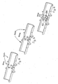
- the sliding means 3 are at the stroke-start 301 of the guide 30. In this position, the sliding means 3 wait for an adequate segment of tube to slide, then they start translating along the tube and as soon as they reach a velocity near the velocity of the tube and as soon as they position the first cutting plane 310 at a distance from the end of the tube equal to the preferential length L, the vices 51 are closed and the cutting operation is executed (see figure 9 ).
- a first segment of length equal to the preferential length L and a second segment of length equal to three times the preferential length L are obtained.
- the vices 51 are opened and the sliding means 3 start to return towards the stroke-start 301 of the guide 30.
- the tube continues to slide in opposite direction and the relative displacements are detected between the tube and the first and the second cutting plane 310, 320 (given by the sum of the absolute displacements of the cutting planes 310, 320 and of the tube). Subsequently, the sliding means 3 stop and resume the motion in the opposite direction.
- the first cutting plane 310 is positioned upstream (relative to the first sense of advance 21 of the tube) and at a distance from the end of the as-yet uncut tube portion equal to the preferential length L.
- a cutting operation is executed, again obtaining a segment with length L equal to the preferential length and a segment whose length is equal to three times the preferential length.
- the operations described above are repeated, to cut the long segment just generated into segments having preferential length L and so on.
- the sliding means 3 At the end of one of the work cycles described above, if the sliding means 3 have no more travel available because they are too close to the stroke-end 302 of the guide 30, they can return in proximity to the stroke-start position 301.
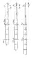
- a subsequent cutting operation downstream of the first cutting plane 310 a segment is generated with a length that is usually pre-set before starting the machining (not necessarily multiple of the desired preferential length L), whilst between the first and the second cutting plane 310, 320 a segment is generated that is equal to or multiple of the desired preferential length L; then, the execution of the various cutting cycles as described previously is resumed.
- the dashed lines orthogonal to the tube represent the areas that will be cut from the cutting planes in the subsequent steps.
- Figures 12 through 14 show the same steps shown in figures 9 through 11 , if the scrap generated by the first and/or by the second cutter 311, 312 is not neglected.
- the scrap generated by the corresponding cutter is shown as a thick line, orthogonal to the tube.
- the invention achieves important advantages.
- Another important advantage is that it allows relatively small dimensions of the machine.
Landscapes
- Engineering & Computer Science (AREA)
- Mechanical Engineering (AREA)
- Life Sciences & Earth Sciences (AREA)
- Forests & Forestry (AREA)
- Shearing Machines (AREA)
- Extrusion Moulding Of Plastics Or The Like (AREA)
Claims (23)
- Methode zum Ablängen von kontinuierlich extrudierten Rohren in vorbestimmte Längen mittels einer Schneidemaschine (1), wobei die Schneidemaschine (1) umfasst:- eine Führung (30), die sich zwischen einem Hubanfang (301) und einem Hubende (302) entwickelt;- Schiebemittel (3), die an der Führung (30) parallel in eine Vorschubrichtung (20) des Rohrs beweglich sind, in die das Rohr gemäß einer ersten Vorschubrichtung (21), gerichtet vom Hubanfang (301) zum Hubende (302) der Führung (30), bearbeitet wird;- Mittel (33) zum Betätigen der genannten Schiebemittel (3) an der Führung (30);die genannten Mittel (3) umfassen eine erste Station (31) zum Schneiden des Rohrs, wobei die erste Schneidstation (31) dagegen ein erstes Schneidwerkzeug (311) umfasst, das eine erste Schneidebene(310) definiert, die quer zur Vorschubrichtung (20) verläuft; wobei die genannten Schiebemittel(3) zudem umfassen:eine zweite Station (32) zum Schneiden des Rohrs, die stromaufwärts der ersten Schneidstation (31) zur ersten Vorschubrichtung (21) des Rohrs entlang der Vorschubrichtung (20) angeordnet ist, wobei die genannte zweite Schneidstation (32) ein zweites Schneidwerkzeug (312) umfasst, das vom ersten Schneidwerkzeug (311) distanziert ist und eine zweite Schneidebene (320) definiert, die quer zur Vorschubrichtung (20) des Rohrs verläuft;Mittel (50) zum Greifen von Rohrabschnitten, wobei die genannten Greifmittel (50) im Vergleich zur ersten Vorschubrichtung (21) des Rohrs stromaufwärts der ersten Schneidebene (310), stromabwärts der zweiten Schneidebene (320) und zwischen der ersten und zweiten Schneidebene (310, 320) angeordnet sind und die genannten Greifmittel zwischen einer ersten Konfiguration, in der sie entsprechende Rohrabschnitte sicher greifen, und einer zweiten Konfiguration, in der sie die genannten Rohrabschnitte freigeben, beweglich sind;die genannte Schneidemaschine (1) umfasst zudem Mittel zur Steuerung der Betätigungsmittel (33) und Mittel zum Messen der entsprechenden Verschiebung zwischen dem genannten Rohr und der genannten ersten und zweiten Schneidebene (310, 320) entlang der Vorschubrichtung (20), wobei die Betätigungsmittel (33) vor jedem Schnitt und auf Befehl der Steuerungsmittel in der Lage sind, die Bewegung jeder Schneidstation (31, 32) entlang der Vorschubrichtung (20) mit der Bewegung des Rohrs zu synchronisieren und die erste und die zweite Schneidebene (310, 320) auf gewünschten Positionen auf dem Rohr zu positionieren;die Steuerungsmittel steuern die genannten Betätigungsmittel (33) der genannten Schiebemittel (3) mindestens gemäß den von den genannten Messmitteln zur Verfügung gestellten Informationen und der gewünschten Länge der mit der Maschine (1) herzustellenden Rohrsegmente;wenn die Synchronisierung abgeschlossen ist, nehmen die genannten Greifmittel (50) vor jedem Schnitt die genannte erste Konfiguration ein, um die Position von Rohrsegmenten, die an der ersten und an der zweiten Schneidebene (310, 320) positioniert sind, beizubehalten, wobei die genannte zweite Konfiguration nach jedem Schnitt eingenommen wird, um die entsprechende Bewegung des Rohrs und der Schiebemittel (3) entlang der Vorschubrichtung (20) des Rohrs zu erlauben;die genannte Methode umfasst folgende Phasen:- Positionieren des Rohrs in einem Arbeitsbereich der Schneidemaschine (1),
wobei das Rohr entlang gemäß der ersten Vorschubrichtung (21) entlang der Vorschubrichtung (20) vorgeschoben wird;- Positionieren der ersten und der zweiten Schneidebene (310, 320) auf einem gegenseitigen Abstand, gleich:
wobei:n eine natürliche Zahl größer als 0 ist;L eine bevorzugte Länge der gewünschten, von der Maschine erzeugten Rohrsegmente, gemessen entlang der Vorschubrichtung des Rohrs, ist;K ein erster Korrekturkoeffizient ist, um die entlang der Rohrvorschubrichtung gemessene Länge des vom ersten und/oder zweiten Schneidwerkzeugs (311, 312) erzeugten Reststücks zu berücksichtigen;- Synchronisieren der Bewegung der ersten und der zweiten Schneidebene (310, 320) entlang der Vorschubrichtung (20) mit der Bewegung des Rohrs;- Ausführen, mindestens teilweise simultan, mittels des ersten und des zweiten Schneidwerkzeugs (311, 312) eines ersten und zweiten Schnitts des Rohrs an der ersten und der zweiten Schneidebene (310, 320). - Methode nach Anspruch 1, dadurch gekennzeichnet, dass nach dem Ausführen des ersten und des zweiten Schnitts, wenn die natürliche Zahl n größer als 1 ist, die Implementierung eines ersten iterativen Vorgangs aktiviert wird, wobei jede Iteration durch einen progressiven Referenzindex i gekennzeichnet ist, dessen Anfangswert einheitlich ist, und wobei der genannte Vorgang unterbrochen wird, wenn der progressive Referenzindex 1 einen Wert annimmt, der der natürlichen Zahl n gleicht, und wobei jeder iterative Zyklus des genannten Vorgangs folgende Schritte umfasst:- Bewirken einer Verschiebung der ersten und der zweiten Schneidebene (310, 320) zum Rohr von Anfangspositionen in neue Positionen, die stromaufwärts der entsprechenden Anfangspositionen im Vergleich zur ersten Vorschubrichtung (21) des Rohrs angeordnet sind, wobei die Verschiebung der ersten und der zweiten Schneidebene (310, 320) entlang der Vorschubrichtung (20) in die Anfangspositionen und in die neuen Positionen im Vergleich zur ersten Vorschubrichtung (21) zu der des Rohrs synchronisiert wird;
die Verschiebung der ersten Schneidebene (310) wird bezüglich eines Punkts bewertet, der mit dem Abschnitt des Rohrs verbunden ist, der bezüglich der ersten Vorschubrichtung des Rohrs (21) an der Anfangsposition der ersten Schneidebene (310) platziert wird, unmittelbar stromaufwärts des ersten Schneidwerkzeugs (311), wobei die genannte Verschiebung der ersten Schneidebene(310) mittels folgender Formel erfolgt:
wobeiL die bevorzugte Länge der gewünschten, von der Maschine erzeugten Rohrsegmente, gemessen entlang der Vorschubrichtung des Rohrs, ist;Y ein zweiter Korrekturkoeffizient ist, um die entlang der Vorschubrichtung des Rohrs gemessene Länge des vom ersten und/oder vom zweiten Schneidwerkzeug (311, 312) erzeugten Reststücks zu berücksichtigen;die Verschiebung der zweiten Schneideebene (320) wird bezüglich eines Punkts bewertet, der mit dem Abschnitt des Rohrs verbunden ist, der bezüglich zur ersten Vorschubrichtung (21) des Rohrs an der Anfangsposition der zweiten Schneidebene (320) platziert wird, unmittelbar stromaufwärts des zweiten Schneidwerkzeugs (312), wobei die genannte Verschiebung der zweiten Schneidebene (320) mittels folgender Formel erfolgt:
wobeiL die bevorzugte Länge der gewünschten, von der Maschine erzeugten Rohrsegmente, gemessen entlang der Vorschubrichtung des Rohrs, ist;X ein dritter Korrekturkoeffizient ist, um die entlang der Vorschubrichtung des Rohrs gemessene Länge des vom ersten und/oder vom zweiten Schneidwerkzeug (311, 312) erzeugten Reststücks zu berücksichtigen;- Schneiden des Rohrs an den neuen Positionen der ersten und der zweiten Schneidebene (310, 320) mittels des ersten und des zweiten Schneidwerkzeugs (311, 312);- Erhöhen des Werts des progressiven Referenzindex i um eine Einheit. - Methode nach Anspruch 2, dadurch gekennzeichnet, dass sie einen zweiten iterativen Vorgang umfasst, der aktiviert wird, wenn der progressive Referenzindex i größer als 1 ist und einen Wert gleich der natürlichen Zahl n annimmt, und wenn die Schiebemittel (3) sich auf einem Abstand befinden, der größer als ein vorgegebener Abstand vom Hubende (302) der Führung (30) ist, wobei der genannte zweite iterative Vorgang unterbrochen wird, wenn sich die Schiebemittel (3) am Ende des iterativen Zyklus auf einem geringeren Abstand als dem vorgegebenen Abstand vom Hubende (302) der Führung (30) befinden, wobei jeder Betriebszyklus des genannten Vorgangs folgende Schritte umfasst:- Bewirken einer Verschiebung der ersten und der zweiten Schneidebene (310, 320) bezüglich des Rohrs von Anfangspositionen in neue Positionen, die stromaufwärts der entsprechenden Anfangspositionen bezüglich der ersten Vorschubrichtung (21) des Rohrs angeordnet sind, wobei die Verschiebung der ersten und der zweiten Schneidebene (310, 320) entlang der Vorschubrichtung (20) in die Anfangspositionen und in die neuen Positionen zu der des Rohrs synchronisiert wird;
die Verschiebung der ersten und der zweiten Schneidebene (310, 320) wird bezüglich eines Punkts bewertet, der mit dem Abschnitt des Rohrs verbunden ist, der bezüglich der ersten Vorschubrichtung (21) des Rohrs an der Anfangsposition der zweiten Schneidebene (320) platziert wird, unmittelbar stromaufwärts des zweiten Schneidwerkzeugs (312), wobei die Verschiebung der ersten Schneidebene und der zweiten Schneidebene (310, 320) jeweils mittels folgender Formeln erfolgt:

wobein die natürliche Zahl größer als 0 ist;L die bevorzugte Länge der gewünschten, von der Maschine erzeugten Rohrsegmente, gemessen entlang der Vorschubrichtung des Rohrs, ist;H ein vierter Korrekturkoeffizient ist, um die entlang der Vorschubrichtung des Rohrs gemessene Länge des vom ersten und/oder vom zweiten Schneidwerkzeug(311, 312) erzeugten Reststücks zu berücksichtigen;Z ein fünfter Korrekturkoeffizient ist, um die entlang der Vorschubrichtung des Rohrs gemessene Länge des vom ersten und/oder vom zweiten Schneidwerkzeug(311, 312) erzeugten Reststücks zu berücksichtigen;- Schneiden des Rohrs an den neuen Positionen der ersten und der zweiten Schneidebene (310, 320) mittels des ersten und des zweiten Schneidwerkzeugs (311, 312);- erneutes Aktivieren des ersten Vorgangs. - Methode nach Anspruch 1, dadurch gekennzeichnet, dass nach dem Ausführen des ersten und des zweiten Schnitts, wenn die natürliche Zahl n einheitlich ist und die Schiebemittel (3) sich auf einem Abstand befinden, der größer ist als ein vorgegebener Abstand vom Hubende (302) der Führung (30), die Implementierung eines zweiten iterativen Vorgangs aktiviert wird; der genannte zweite iterative Vorgang wird unterbrochen, wenn sich die Schiebemittel (3) am Ende eines iterativen Zyklus auf einem geringeren Abstand als dem vorgegebenen Abstand vom Hubende (302) der Führung (30) befinden, wobei jeder Betriebszyklus des genannten zweiten Vorgangs folgende Schritte umfasst:- Bewirken einer Verschiebung der ersten und der zweiten Schneidebene (310, 320) bezüglich des Rohrs von Anfangspositionen in neue Positionen, die stromaufwärts der entsprechenden Anfangspositionen bezüglich der ersten Vorschubrichtung (21) des Rohrs angeordnet sind, wobei die Verschiebung der ersten und der zweiten Schneidebene (310, 320) entlang der Vorschubrichtung (20) in die Anfangspositionen und in die neuen Positionen zu der des Rohrs synchronisiert wird;
die Verschiebung der ersten und der zweiten Schneidebene (310, 320) wird bezüglich eines Punkts hinsichtlich des Abschnitts des Rohrs bewertet, der an der Anfangsposition der zweiten Schneidebene (320) platziert wird, im Vergleich zur ersten Vorschubrichtung (21) des Rohrs, unmittelbar stromaufwärts des zweiten Schneidwerkzeugs (312), wobei die Verschiebung der ersten Schneidebene und der zweiten Schneidebene (310, 320) jeweils mittels folgender Formeln erfolgt:

wobeiL die bevorzugte Länge der gewünschten, von der Maschine erzeugten Rohrsegmente, gemessen entlang der Vorschubrichtung des Rohrs, ist;H ein vierter Korrekturkoeffizient ist, um die entlang der Vorschubrichtung des Rohrs gemessene Länge des vom ersten und/oder vom zweiten Schneidwerkzeug (311, 312) erzeugten Reststücks zu berücksichtigen;Z ein fünfter Korrekturkoeffizient ist, um die entlang der Vorschubrichtung des Rohrs gemessene Länge des vom ersten und/oder vom zweiten Schneidwerkzeug (311, 312) erzeugten Reststücks zu berücksichtigen;- Schneiden des Rohrs an den neuen Positionen der ersten und der zweiten Schneidebene (310, 320) mittels des ersten und des zweiten Schneidwerkzeugs (311, 312); - Methode nach Anspruch 3 oder 4, dadurch gekennzeichnet, dass der erste und der zweite und der dritte und der vierte und der fünfte Korrekturkoeffizient zwei verschiedene Wertesätze annehmen:- einen ersten Wertesatz, bei dem der erste, der zweite, der dritte, der vierte und der fünfte Korrekturkoeffizient null sind, wobei das Reststück des Rohrs, das vom ersten und dem zweiten Schneidwerkzeug 311, 312 erzeugt wird, in diesem Fall vernachlässigt wird;- einen zweiten Wertesatz, bei dem der erste, der zweite, der dritte, der vierte und der fünfte Korrekturkoeffizient das vom ersten und/oder zweiten Schneidwerkzeug (311, 312) erzeugte Reststück berücksichtigen, wobei in diesem Fall jedem Schneidwerkzeug (311, 312) Mehrfachschneidebenen in einem Intervall, definiert durch die Länge des vom entsprechenden Schneidwerkzeug (311, 312) erzeugten Reststücks in Vorschubrichtung (20) des Rohrs, zugeordnet werden und die ersten und zweiten Schneidebenen (310, 320) mit den zwei gegenseitig sich am nächsten liegenden Schneidebenen übereinstimmen, erzeugt mindestens teilweise simultan durch das erste Schneidwerkzeug (311) und durch das zweite Schneidwerkzeug (312); wobei der erste, der zweite, der dritte, der vierte und der fünfte Korrekturkoeffizient beim zweiten Wertesatz die Werte annehmen, die auf folgenden Relationen basieren:


wobein die natürliche Zahl größer als 0 ist;L die bevorzugte Länge der gewünschten, von der Maschine erzeugten Rohrsegmente, gemessen entlang der Vorschubrichtung des Rohrs, ist;K ein erster Korrekturkoeffizient ist, um die entlang der Vorschubrichtung des Rohrs gemessene Länge des vom ersten und/oder vom zweiten Schneidwerkzeug (311, 312) erzeugten Reststücks zu berücksichtigen;Y der zweite Korrekturkoeffizient ist, um die entlang der Vorschubrichtung des Rohrs gemessene Länge des vom ersten und/oder vom zweiten Schneidwerkzeug (311, 312) erzeugten Reststücks zu berücksichtigen;X der dritte Korrekturkoeffizient ist, um die entlang der Vorschubrichtung des Rohrs gemessene Länge des vom ersten und/oder vom zweiten Schneidwerkzeug (311, 312) erzeugten Reststücks zu berücksichtigen;H der vierte Korrekturkoeffizient ist, um die entlang der Vorschubrichtung des Rohrs gemessene Länge des vom ersten und/oder vom zweiten Schneidwerkzeug (311, 312) erzeugten Reststücks zu berücksichtigen;Z der fünfte Korrekturkoeffizient ist, um die entlang der Vorschubrichtung des Rohrs gemessene Länge des vom ersten und/oder vom zweiten Schneidwerkzeug (311, 312) erzeugten Reststücks zu berücksichtigen;S1 die Länge des Reststücks ist, gemessen entlang der Vorschubrichtung des Rohrs, erzeugt vom ersten Schneidwerkzeug(311);S2 die Länge des Reststücks ist, gemessen entlang der Vorschubrichtung des Rohrs, erzeugt vom zweiten Schneidwerkzeug(312); - Methode nach einem der vorhergehenden Ansprüche, dadurch gekennzeichnet, dass der genannte erste iterative Vorgang, wenn der progressive Referenzindex i kleiner als die natürliche Zahl n ist, dafür sorgt, dass der Schritt des Bewegens der ersten und der zweiten Schneidebene (310, 320) von den Anfangspositionen in neue Positionen den Schritt des gegenseitigen Annäherns der zweiten Schneidebene (320) und der ersten Schneidebene (310) durch eine Menge gleich dem zweiten Korrekturkoeffizienten Y umfasst.
- Methode nach Anspruch 6, dadurch gekennzeichnet, dass sie den folgenden Schritt umfasst, wenn der progressive Referenzindex i einen Wert gleich der natürlichen Zahl n annimmt: Zurückbringen des Abstands zwischen der ersten und der zweiten Schneidebene (310, 320) auf den Abstand gemäß der folgenden Formel:

wobein eine natürliche Zahl größer als 0 ist;L die bevorzugte Länge der gewünschten, von der Maschine erzeugten Rohrsegmente, gemessen entlang der Vorschubrichtung des Rohrs, ist;K der erste Korrekturkoeffizient ist, um die entlang der Vorschubrichtung des Rohrs gemessene Länge des vom ersten und/oder vom zweiten Schneidwerkzeug (311, 312) erzeugten Reststücks zu berücksichtigen; - Methode nach einem der vorhergehenden Ansprüche, dadurch gekennzeichnet, dass sie das Einstellen des Werts der bevorzugten Länge L der gewünschten, von der Maschine (1) erzeugten Rohrsegmente, gemessen entlang der Rohrvorschubrichtung, umfasst.
- Methode nach einem der vorhergehenden Ansprüche, dadurch gekennzeichnet, dass sie die Auswahl des kleinsten Werts von "n" umfasst, was das Erzielen des auf folgender Relation basierenden Werts erlaubt:

zwischen einem vorgegebenen Mindest- und Höchstwert. - Methode nach einem der vorhergehenden Ansprüche, dadurch gekennzeichnet, dass sie die Einstellung des gegenseitigen Abstand der ersten und der zweiten Schneidebene (310, 320) umfasst.
- Methode nach einem der vorhergehenden Ansprüche, dadurch gekennzeichnet, dass der Wert der natürlichen Zahl größer als 1 ist.
- Methode nach einem der vorhergehenden Ansprüche, dadurch gekennzeichnet, dass die Maschine (1) Mittel zum Positionieren der ersten und der zweiten Schneidebene (310, 320) auf einem gegenseitigen Abstand, definiert durch folgende Formel, umfasst:

wobein die natürliche Zahl größer als 0 ist;L die bevorzugte Länge der gewünschten, von der Maschine erzeugten Rohrsegmente, gemessen entlang der Vorschubrichtung des Rohrs, ist;K der erste Korrekturkoeffizient ist, um die entlang der Vorschubrichtung des Rohrs gemessene Länge des vom ersten und/oder vom zweiten Schneidwerkzeug (311, 312) erzeugten Reststücks zu berücksichtigen; - Methode nach Anspruch 12, dadurch gekennzeichnet, dass die Maschine (1) eine Benutzeroberfläche umfasst, um den Wert der bevorzugten Länge L der gewünschten, von der Maschine erzeugten Rohrsegmente festzulegen.
- Methode nach Anspruch 12 oder 13, dadurch gekennzeichnet, dass die Maschine (1) eine elektronische Einheit umfasst, die den Wert der natürlichen Zahl n als eine Funktion des Werts der bevorzugten Länge L der gewünschten von der Maschine (1) erzeugten Segmente sowie von voreingestellten geometrischen Parametern der Maschine bestimmt.
- Methode nach einem der vorhergehenden Ansprüche, dadurch gekennzeichnet, dass die genannten Betätigungsmittel (33) in der Maschine (1) Mittel (330) zum Regulieren des gegenseitigen Abstands der ersten und der zweiten Schneidebene (310, 320) umfassen.
- Methode nach Anspruch 15, dadurch gekennzeichnet, dass die Maschine (1) eine Fernsteuerung zum Steuern der Regulierungsmittel (330) umfasst, die das Aktivieren der Regulierungsmittel (330) ohne Stillsetzen der Maschine (1) ermöglicht.
- Methode nach einem der vorhergehenden Ansprüche, dadurch gekennzeichnet, dass die genannten Schiebemittel (3) in der Maschine (1) umfassen:- einen ersten Wagen, der entlang der genannten Führungsmittel (30) beweglich ist, wobei die erste Schneidstation (31) auf dem genannten ersten Wagen ausgebildet ist;- einen zweiten Wagen, der parallel zur Vorschubrichtung (20) des Rohrs beweglich ist, wobei die zweite Schneidstation (32) auf dem genannten zweiten Wagen ausgebildet ist;der genannte erste und zweite Wagen sind physikalisch voneinander mindestens entlang der Vorschubrichtung (20) des Rohrs getrennt.
- Methode nach einem der vorhergehenden Ansprüche, dadurch gekennzeichnet, dass die genannten Greifmittel (50) in der Maschine (1) Spannelemente (51) umfassen, die in der ersten Konfiguration am Rohr festgespannt werden.
- Methode nach Anspruch 18, dadurch gekennzeichnet, dass jedes Spannelement (51) in der Maschine (1) mindestens einen unteren Teil (511) und einen oberen Teil (512) umfasst, die zueinander beweglich ist, wobei in der ersten Konfiguration der Greifmittel (50) sowohl der untere Teil (511) als auch der obere Teil (512) am Rohr festgespannt werden, und in der zweiten Konfiguration der Greifmittel (50) der obere Teil (512) vom Rohr entfernt wird, um das gegenseitige Verschieben des Rohrs zum Spannelement (51) zu ermöglichen.
- Methode nach Anspruch 19, dadurch gekennzeichnet, dass die unteren Teile (511) der Spannelemente (51) in der Maschine (1) mindestens einen Teil der Segmente des geschnittenen Rohrs tragen.
- Methode nach Anspruch 18 oder 19 oder 20, dadurch gekennzeichnet, dass die genannten Spannelemente (51) in der Maschine (1) ausgerichtet sind und die Vorschubrichtung (20) definieren.
- Methode nach einem der Ansprüche 18 bis 21, dadurch gekennzeichnet, dass rittlings der ersten Schneidebene (310) in der Maschine (1) ein erstes Paar Spannelemente (51), rittlings der zweiten Schneidebene (320) ein zweites Paar Spannelemente (51) angeordnet sind, wobei das erste Paar Spannelemente (51) vom genannten zweiten Paar Spannelemente(51) verschieden ist.
- Methode nach einem der Ansprüche 18 bis 22, dadurch gekennzeichnet, dass in der Maschine (1) zwischen der ersten und der zweiten Schneidebene (310, 320) zwei Spannelemente (51) zur Verfügung stehen, eines verbunden mit der ersten Schneidstation (31) und eines verbunden mit der zweiten Schneidstation (32), wobei mindestens eines der genannten Spannelemente (51) Zähne (52) umfasst, die beide ergänzend geformt und gegenständig zu Vertiefungen (52) angeordnet sind, die am anderen Spannelement (51) ausgebildet sind, wobei das Einsetzen oder Herausnehmen der Zähne (52) aus den entsprechenden Vertiefungen (53) das zumindest teilweise Ineinandergreifen eines Spannelements (51) in das andere erlaubt, um das gegenseitige Annähern oder Entfernen der ersten und der zweiten Schneidestation (31) in Vorschubrichtung (20) zu kompensieren.
Priority Applications (4)
| Application Number | Priority Date | Filing Date | Title |
|---|---|---|---|
| EP07425393A EP2008749B1 (de) | 2007-06-27 | 2007-06-27 | Methode zum Ablängen von kontinuierlich extrudierten Rohren in vorbestimmte Längen. |
| AT07425393T ATE519553T1 (de) | 2007-06-27 | 2007-06-27 | Methode zum ablängen von kontinuierlich extrudierten rohren in vorbestimmte längen. |
| ES07425393T ES2371417T3 (es) | 2007-06-27 | 2007-06-27 | Método para cortar un tubo extruido en continuo en segmentos de menor y predeterminada longitud. |
| PT07425393T PT2008749E (pt) | 2007-06-27 | 2007-06-27 | Método para cortar um tubo extrudido em contínuo em segmentos de comprimento menor e predeterminado |
Applications Claiming Priority (1)
| Application Number | Priority Date | Filing Date | Title |
|---|---|---|---|
| EP07425393A EP2008749B1 (de) | 2007-06-27 | 2007-06-27 | Methode zum Ablängen von kontinuierlich extrudierten Rohren in vorbestimmte Längen. |
Publications (2)
| Publication Number | Publication Date |
|---|---|
| EP2008749A1 EP2008749A1 (de) | 2008-12-31 |
| EP2008749B1 true EP2008749B1 (de) | 2011-08-10 |
Family
ID=38686624
Family Applications (1)
| Application Number | Title | Priority Date | Filing Date |
|---|---|---|---|
| EP07425393A Active EP2008749B1 (de) | 2007-06-27 | 2007-06-27 | Methode zum Ablängen von kontinuierlich extrudierten Rohren in vorbestimmte Längen. |
Country Status (4)
| Country | Link |
|---|---|
| EP (1) | EP2008749B1 (de) |
| AT (1) | ATE519553T1 (de) |
| ES (1) | ES2371417T3 (de) |
| PT (1) | PT2008749E (de) |
Families Citing this family (14)
| Publication number | Priority date | Publication date | Assignee | Title |
|---|---|---|---|---|
| CN101885187B (zh) * | 2010-07-09 | 2011-12-14 | 太原重工股份有限公司 | 一种碳素挤压机的随动剪切装置 |
| CN103722580B (zh) * | 2013-12-31 | 2015-07-29 | 浙江安浦科技有限公司 | 铜箔连续裁切伺服机构 |
| CN105458301B (zh) * | 2016-01-12 | 2018-07-20 | 大连富地重工机械制造有限公司 | 一种多车串联同步定尺切断连续成型物料的新方法 |
| EP3275581A1 (de) | 2016-07-26 | 2018-01-31 | Aisapack Holding SA | Rotierendes schneidwerkzeug für maschine zur herstellung von verpackungen, und verfahren, bei dem dieses schneidwerkzeug zum einsatz kommt |
| IT201600105300A1 (it) * | 2016-10-19 | 2018-04-19 | Manz Italy Srl | Metodo e apparato di lavorazione |
| CN107414934B (zh) * | 2017-06-23 | 2018-11-13 | 中北大学 | 一种在线环式切断装置 |
| CN110091180A (zh) * | 2018-01-31 | 2019-08-06 | 佛山市源锐鑫机械模具有限公司 | 一种不锈钢管制造生产用智能化全自动流水线 |
| IT201900018368A1 (it) * | 2019-10-10 | 2021-04-10 | Baruffaldi Plastic Tech S R L | Gruppo di taglio per elementi tubolari |
| CN111923115A (zh) * | 2020-08-18 | 2020-11-13 | 重庆泽通管业科技有限公司 | 一种增强型聚乙烯缠绕管切割装置 |
| CN112496435A (zh) * | 2020-11-14 | 2021-03-16 | 刘杰 | 一种用于轨道交通的作业工装 |
| CN112589863B (zh) * | 2021-01-14 | 2021-09-07 | 新疆志成兴管业有限公司 | 一种能够测距切割的pvc管切割装置 |
| CN113199545A (zh) * | 2021-04-21 | 2021-08-03 | 天津弘创博实科技发展有限公司 | 一种书刊的夹紧设备及生产设备 |
| CN114280375B (zh) * | 2021-12-24 | 2025-04-29 | 江苏中天科技股份有限公司 | 一种线材的电阻检测装置及检测方法 |
| IT202200014644A1 (it) | 2022-07-12 | 2024-01-12 | Sica Spa | Apparato e metodo di distribuzione di tubi in materiale termoplastico ad una macchina bicchieratrice. |
Family Cites Families (4)
| Publication number | Priority date | Publication date | Assignee | Title |
|---|---|---|---|---|
| GB1392637A (en) * | 1972-12-11 | 1975-04-30 | Speedex Eng Ltd | Plastics extrusion cutting-off machines |
| IT1171937B (it) | 1983-06-21 | 1987-06-10 | Sica Spa | Apparecchiatura e procedimento di controllo delle fasi di lavoro di un dispositivo di taglio mobile su tubi estrusi in continuo |
| US5224368A (en) | 1992-04-03 | 1993-07-06 | Schach Herbert U | Flying die machine |
| FI115705B (sv) * | 2002-04-26 | 2005-06-30 | Paroc Group Oy Ab | Förfarande och anordning för skärning av en rörlig bana |
-
2007
- 2007-06-27 EP EP07425393A patent/EP2008749B1/de active Active
- 2007-06-27 PT PT07425393T patent/PT2008749E/pt unknown
- 2007-06-27 ES ES07425393T patent/ES2371417T3/es active Active
- 2007-06-27 AT AT07425393T patent/ATE519553T1/de active
Also Published As
| Publication number | Publication date |
|---|---|
| ATE519553T1 (de) | 2011-08-15 |
| ES2371417T3 (es) | 2012-01-02 |
| PT2008749E (pt) | 2011-11-21 |
| EP2008749A1 (de) | 2008-12-31 |
Similar Documents
| Publication | Publication Date | Title |
|---|---|---|
| EP2008749B1 (de) | Methode zum Ablängen von kontinuierlich extrudierten Rohren in vorbestimmte Längen. | |
| US8630730B2 (en) | Machine and method for cutting | |
| US4362187A (en) | Spirally-formed thermoplastic tube | |
| KR101531573B1 (ko) | 파이프 절단 및 개선 장치 | |
| CN110142451B (zh) | 一种基于剪切长度的自适应飞剪定位控制方法 | |
| WO2011099176A1 (ja) | 丸鋸切断機 | |
| US5406870A (en) | Method and apparatus for cutting tubing | |
| CN105764656A (zh) | 用于挤出的塑料型材的定长剪切装置 | |
| US9969096B2 (en) | Device for cutting extruded plastics profiles to length | |
| CN101983361B (zh) | 用于控制激光切割设备的方法 | |
| ATE58077T1 (de) | Verfahren zur kontrolle von fertigungsschritten einer auf kontinuierlich stranggepressten rohren beweglichen schneidvorrichtung. | |
| CN102248446B (zh) | 坡口机智能控制系统 | |
| CN204159973U (zh) | 自动定位型材的切割机器 | |
| CN109397374B (zh) | 一种防腐保温管道保温泡沫层切割刀具 | |
| CN105710233A (zh) | 管材成型机 | |
| WO2007130141A2 (en) | Spiral pipe machine | |
| CN116673617A (zh) | 一种零尾料切管方法及三卡盘切管机 | |
| CN109624287B (zh) | 端封主机 | |
| CN111203460A (zh) | 一种折弯机全自动送料装置 | |
| CN211761841U (zh) | 一种塑料管定长裁切装置 | |
| CN209394741U (zh) | 一种防腐保温管道保温泡沫层切割机 | |
| US6619162B1 (en) | Device for cutting tubes | |
| CN109760130A (zh) | 切割装置、冲孔切割装置及其控制方法 | |
| CN211072024U (zh) | 一种伺服定位切割自动对刀装置 | |
| DE60316360D1 (de) | Schneideeinheit zum schneiden der oberfläche eines teigstückes zu einer gleichen tiefe |
Legal Events
| Date | Code | Title | Description |
|---|---|---|---|
| PUAI | Public reference made under article 153(3) epc to a published international application that has entered the european phase |
Free format text: ORIGINAL CODE: 0009012 |
|
| 17P | Request for examination filed |
Effective date: 20080929 |
|
| AK | Designated contracting states |
Kind code of ref document: A1 Designated state(s): AT BE BG CH CY CZ DE DK EE ES FI FR GB GR HU IE IS IT LI LT LU LV MC MT NL PL PT RO SE SI SK TR |
|
| AX | Request for extension of the european patent |
Extension state: AL BA HR MK RS |
|
| 17Q | First examination report despatched |
Effective date: 20090414 |
|
| AKX | Designation fees paid |
Designated state(s): AT BE BG CH CY CZ DE DK EE ES FI FR GB GR HU IE IS IT LI LT LU LV MC MT NL PL PT RO SE SI SK TR |
|
| AXX | Extension fees paid |
Extension state: RS Payment date: 20080929 Extension state: HR Payment date: 20080929 Extension state: AL Payment date: 20080929 Extension state: MK Payment date: 20080929 Extension state: BA Payment date: 20080929 |
|
| GRAP | Despatch of communication of intention to grant a patent |
Free format text: ORIGINAL CODE: EPIDOSNIGR1 |
|
| RTI1 | Title (correction) |
Free format text: METHOD FOR CUTTING A CONTINUOUSLY EXTRUDED TUBE INTO SEGMENTS OF LESSER AND PREDETERMINED LENGTH |
|
| GRAS | Grant fee paid |
Free format text: ORIGINAL CODE: EPIDOSNIGR3 |
|
| GRAA | (expected) grant |
Free format text: ORIGINAL CODE: 0009210 |
|
| AK | Designated contracting states |
Kind code of ref document: B1 Designated state(s): AT BE BG CH CY CZ DE DK EE ES FI FR GB GR HU IE IS IT LI LT LU LV MC MT NL PL PT RO SE SI SK TR |
|
| AX | Request for extension of the european patent |
Extension state: AL BA HR MK RS |
|
| REG | Reference to a national code |
Ref country code: GB Ref legal event code: FG4D |
|
| REG | Reference to a national code |
Ref country code: CH Ref legal event code: EP |
|
| REG | Reference to a national code |
Ref country code: IE Ref legal event code: FG4D |
|
| REG | Reference to a national code |
Ref country code: DE Ref legal event code: R096 Ref document number: 602007016410 Country of ref document: DE Effective date: 20111013 |
|
| REG | Reference to a national code |
Ref country code: PT Ref legal event code: SC4A Free format text: AVAILABILITY OF NATIONAL TRANSLATION Effective date: 20111104 |
|
| REG | Reference to a national code |
Ref country code: NL Ref legal event code: T3 |
|
| REG | Reference to a national code |
Ref country code: ES Ref legal event code: FG2A Ref document number: 2371417 Country of ref document: ES Kind code of ref document: T3 Effective date: 20120102 |
|
| LTIE | Lt: invalidation of european patent or patent extension |
Effective date: 20110810 |
|
| PG25 | Lapsed in a contracting state [announced via postgrant information from national office to epo] |
Ref country code: LT Free format text: LAPSE BECAUSE OF FAILURE TO SUBMIT A TRANSLATION OF THE DESCRIPTION OR TO PAY THE FEE WITHIN THE PRESCRIBED TIME-LIMIT Effective date: 20110810 Ref country code: SE Free format text: LAPSE BECAUSE OF FAILURE TO SUBMIT A TRANSLATION OF THE DESCRIPTION OR TO PAY THE FEE WITHIN THE PRESCRIBED TIME-LIMIT Effective date: 20110810 Ref country code: IS Free format text: LAPSE BECAUSE OF FAILURE TO SUBMIT A TRANSLATION OF THE DESCRIPTION OR TO PAY THE FEE WITHIN THE PRESCRIBED TIME-LIMIT Effective date: 20111210 |
|
| PG25 | Lapsed in a contracting state [announced via postgrant information from national office to epo] |
Ref country code: SI Free format text: LAPSE BECAUSE OF FAILURE TO SUBMIT A TRANSLATION OF THE DESCRIPTION OR TO PAY THE FEE WITHIN THE PRESCRIBED TIME-LIMIT Effective date: 20110810 Ref country code: LV Free format text: LAPSE BECAUSE OF FAILURE TO SUBMIT A TRANSLATION OF THE DESCRIPTION OR TO PAY THE FEE WITHIN THE PRESCRIBED TIME-LIMIT Effective date: 20110810 Ref country code: PL Free format text: LAPSE BECAUSE OF FAILURE TO SUBMIT A TRANSLATION OF THE DESCRIPTION OR TO PAY THE FEE WITHIN THE PRESCRIBED TIME-LIMIT Effective date: 20110810 Ref country code: CY Free format text: LAPSE BECAUSE OF FAILURE TO SUBMIT A TRANSLATION OF THE DESCRIPTION OR TO PAY THE FEE WITHIN THE PRESCRIBED TIME-LIMIT Effective date: 20110810 Ref country code: GR Free format text: LAPSE BECAUSE OF FAILURE TO SUBMIT A TRANSLATION OF THE DESCRIPTION OR TO PAY THE FEE WITHIN THE PRESCRIBED TIME-LIMIT Effective date: 20111111 |
|
| PG25 | Lapsed in a contracting state [announced via postgrant information from national office to epo] |
Ref country code: BE Free format text: LAPSE BECAUSE OF FAILURE TO SUBMIT A TRANSLATION OF THE DESCRIPTION OR TO PAY THE FEE WITHIN THE PRESCRIBED TIME-LIMIT Effective date: 20110810 |
|
| PG25 | Lapsed in a contracting state [announced via postgrant information from national office to epo] |
Ref country code: SK Free format text: LAPSE BECAUSE OF FAILURE TO SUBMIT A TRANSLATION OF THE DESCRIPTION OR TO PAY THE FEE WITHIN THE PRESCRIBED TIME-LIMIT Effective date: 20110810 Ref country code: CZ Free format text: LAPSE BECAUSE OF FAILURE TO SUBMIT A TRANSLATION OF THE DESCRIPTION OR TO PAY THE FEE WITHIN THE PRESCRIBED TIME-LIMIT Effective date: 20110810 |
|
| PG25 | Lapsed in a contracting state [announced via postgrant information from national office to epo] |
Ref country code: EE Free format text: LAPSE BECAUSE OF FAILURE TO SUBMIT A TRANSLATION OF THE DESCRIPTION OR TO PAY THE FEE WITHIN THE PRESCRIBED TIME-LIMIT Effective date: 20110810 Ref country code: RO Free format text: LAPSE BECAUSE OF FAILURE TO SUBMIT A TRANSLATION OF THE DESCRIPTION OR TO PAY THE FEE WITHIN THE PRESCRIBED TIME-LIMIT Effective date: 20110810 |
|
| PLBE | No opposition filed within time limit |
Free format text: ORIGINAL CODE: 0009261 |
|
| STAA | Information on the status of an ep patent application or granted ep patent |
Free format text: STATUS: NO OPPOSITION FILED WITHIN TIME LIMIT |
|
| PG25 | Lapsed in a contracting state [announced via postgrant information from national office to epo] |
Ref country code: DK Free format text: LAPSE BECAUSE OF FAILURE TO SUBMIT A TRANSLATION OF THE DESCRIPTION OR TO PAY THE FEE WITHIN THE PRESCRIBED TIME-LIMIT Effective date: 20110810 |
|
| 26N | No opposition filed |
Effective date: 20120511 |
|
| REG | Reference to a national code |
Ref country code: DE Ref legal event code: R097 Ref document number: 602007016410 Country of ref document: DE Effective date: 20120511 |
|
| PG25 | Lapsed in a contracting state [announced via postgrant information from national office to epo] |
Ref country code: MC Free format text: LAPSE BECAUSE OF NON-PAYMENT OF DUE FEES Effective date: 20120630 |
|
| REG | Reference to a national code |
Ref country code: CH Ref legal event code: PL |
|
| REG | Reference to a national code |
Ref country code: CH Ref legal event code: PL |
|
| REG | Reference to a national code |
Ref country code: IE Ref legal event code: MM4A |
|
| PG25 | Lapsed in a contracting state [announced via postgrant information from national office to epo] |
Ref country code: CH Free format text: LAPSE BECAUSE OF NON-PAYMENT OF DUE FEES Effective date: 20120630 Ref country code: IE Free format text: LAPSE BECAUSE OF NON-PAYMENT OF DUE FEES Effective date: 20120627 Ref country code: LI Free format text: LAPSE BECAUSE OF NON-PAYMENT OF DUE FEES Effective date: 20120630 |
|
| PG25 | Lapsed in a contracting state [announced via postgrant information from national office to epo] |
Ref country code: BG Free format text: LAPSE BECAUSE OF FAILURE TO SUBMIT A TRANSLATION OF THE DESCRIPTION OR TO PAY THE FEE WITHIN THE PRESCRIBED TIME-LIMIT Effective date: 20111110 |
|
| PG25 | Lapsed in a contracting state [announced via postgrant information from national office to epo] |
Ref country code: MT Free format text: LAPSE BECAUSE OF FAILURE TO SUBMIT A TRANSLATION OF THE DESCRIPTION OR TO PAY THE FEE WITHIN THE PRESCRIBED TIME-LIMIT Effective date: 20110810 |
|
| PG25 | Lapsed in a contracting state [announced via postgrant information from national office to epo] |
Ref country code: LU Free format text: LAPSE BECAUSE OF NON-PAYMENT OF DUE FEES Effective date: 20120627 |
|
| PG25 | Lapsed in a contracting state [announced via postgrant information from national office to epo] |
Ref country code: HU Free format text: LAPSE BECAUSE OF FAILURE TO SUBMIT A TRANSLATION OF THE DESCRIPTION OR TO PAY THE FEE WITHIN THE PRESCRIBED TIME-LIMIT Effective date: 20070627 |
|
| REG | Reference to a national code |
Ref country code: FR Ref legal event code: PLFP Year of fee payment: 10 |
|
| REG | Reference to a national code |
Ref country code: FR Ref legal event code: PLFP Year of fee payment: 11 |
|
| REG | Reference to a national code |
Ref country code: FR Ref legal event code: PLFP Year of fee payment: 12 |
|
| PGFP | Annual fee paid to national office [announced via postgrant information from national office to epo] |
Ref country code: PT Payment date: 20200609 Year of fee payment: 14 Ref country code: FR Payment date: 20200626 Year of fee payment: 14 Ref country code: FI Payment date: 20200622 Year of fee payment: 14 |
|
| PGFP | Annual fee paid to national office [announced via postgrant information from national office to epo] |
Ref country code: GB Payment date: 20200629 Year of fee payment: 14 |
|
| PGFP | Annual fee paid to national office [announced via postgrant information from national office to epo] |
Ref country code: ES Payment date: 20200710 Year of fee payment: 14 |
|
| REG | Reference to a national code |
Ref country code: FI Ref legal event code: MAE |
|
| PG25 | Lapsed in a contracting state [announced via postgrant information from national office to epo] |
Ref country code: PT Free format text: LAPSE BECAUSE OF NON-PAYMENT OF DUE FEES Effective date: 20211227 Ref country code: FI Free format text: LAPSE BECAUSE OF NON-PAYMENT OF DUE FEES Effective date: 20210627 |
|
| GBPC | Gb: european patent ceased through non-payment of renewal fee |
Effective date: 20210627 |
|
| PG25 | Lapsed in a contracting state [announced via postgrant information from national office to epo] |
Ref country code: GB Free format text: LAPSE BECAUSE OF NON-PAYMENT OF DUE FEES Effective date: 20210627 |
|
| PG25 | Lapsed in a contracting state [announced via postgrant information from national office to epo] |
Ref country code: FR Free format text: LAPSE BECAUSE OF NON-PAYMENT OF DUE FEES Effective date: 20210630 |
|
| REG | Reference to a national code |
Ref country code: ES Ref legal event code: FD2A Effective date: 20220830 |
|
| PG25 | Lapsed in a contracting state [announced via postgrant information from national office to epo] |
Ref country code: ES Free format text: LAPSE BECAUSE OF NON-PAYMENT OF DUE FEES Effective date: 20210628 |
|
| P01 | Opt-out of the competence of the unified patent court (upc) registered |
Effective date: 20230517 |
|
| PGFP | Annual fee paid to national office [announced via postgrant information from national office to epo] |
Ref country code: DE Payment date: 20240627 Year of fee payment: 18 |
|
| PGFP | Annual fee paid to national office [announced via postgrant information from national office to epo] |
Ref country code: NL Payment date: 20240625 Year of fee payment: 18 |
|
| PGFP | Annual fee paid to national office [announced via postgrant information from national office to epo] |
Ref country code: AT Payment date: 20240618 Year of fee payment: 18 |
|
| PGFP | Annual fee paid to national office [announced via postgrant information from national office to epo] |
Ref country code: TR Payment date: 20240610 Year of fee payment: 18 |
|
| PGFP | Annual fee paid to national office [announced via postgrant information from national office to epo] |
Ref country code: IT Payment date: 20250612 Year of fee payment: 19 |
|
| REG | Reference to a national code |
Ref country code: DE Ref legal event code: R119 Ref document number: 602007016410 Country of ref document: DE |
|
| REG | Reference to a national code |
Ref country code: NL Ref legal event code: MM Effective date: 20250701 |
|
| REG | Reference to a national code |
Ref country code: AT Ref legal event code: MM01 Ref document number: 519553 Country of ref document: AT Kind code of ref document: T Effective date: 20250627 |
|
| PG25 | Lapsed in a contracting state [announced via postgrant information from national office to epo] |
Ref country code: NL Free format text: LAPSE BECAUSE OF NON-PAYMENT OF DUE FEES Effective date: 20250701 |
|
| PG25 | Lapsed in a contracting state [announced via postgrant information from national office to epo] |
Ref country code: DE Free format text: LAPSE BECAUSE OF NON-PAYMENT OF DUE FEES Effective date: 20260101 |
|
| PG25 | Lapsed in a contracting state [announced via postgrant information from national office to epo] |
Ref country code: AT Free format text: LAPSE BECAUSE OF NON-PAYMENT OF DUE FEES Effective date: 20250627 |