EP2008791B1 - Verfahren zur Durchführung des Schließkraftabbaus bei einer Schließeinheit einer Spritzgießmaschine - Google Patents
Verfahren zur Durchführung des Schließkraftabbaus bei einer Schließeinheit einer Spritzgießmaschine Download PDFInfo
- Publication number
- EP2008791B1 EP2008791B1 EP08010851A EP08010851A EP2008791B1 EP 2008791 B1 EP2008791 B1 EP 2008791B1 EP 08010851 A EP08010851 A EP 08010851A EP 08010851 A EP08010851 A EP 08010851A EP 2008791 B1 EP2008791 B1 EP 2008791B1
- Authority
- EP
- European Patent Office
- Prior art keywords
- pressure
- relaxation
- clamping
- time
- force
- Prior art date
- Legal status (The legal status is an assumption and is not a legal conclusion. Google has not performed a legal analysis and makes no representation as to the accuracy of the status listed.)
- Active
Links
Images
Classifications
-
- B—PERFORMING OPERATIONS; TRANSPORTING
- B29—WORKING OF PLASTICS; WORKING OF SUBSTANCES IN A PLASTIC STATE IN GENERAL
- B29C—SHAPING OR JOINING OF PLASTICS; SHAPING OF MATERIAL IN A PLASTIC STATE, NOT OTHERWISE PROVIDED FOR; AFTER-TREATMENT OF THE SHAPED PRODUCTS, e.g. REPAIRING
- B29C45/00—Injection moulding, i.e. forcing the required volume of moulding material through a nozzle into a closed mould; Apparatus therefor
- B29C45/17—Component parts, details or accessories; Auxiliary operations
- B29C45/76—Measuring, controlling or regulating
- B29C45/7653—Measuring, controlling or regulating mould clamping forces
-
- B—PERFORMING OPERATIONS; TRANSPORTING
- B29—WORKING OF PLASTICS; WORKING OF SUBSTANCES IN A PLASTIC STATE IN GENERAL
- B29C—SHAPING OR JOINING OF PLASTICS; SHAPING OF MATERIAL IN A PLASTIC STATE, NOT OTHERWISE PROVIDED FOR; AFTER-TREATMENT OF THE SHAPED PRODUCTS, e.g. REPAIRING
- B29C2945/00—Indexing scheme relating to injection moulding, i.e. forcing the required volume of moulding material through a nozzle into a closed mould
- B29C2945/76—Measuring, controlling or regulating
- B29C2945/76003—Measured parameter
- B29C2945/76006—Pressure
-
- B—PERFORMING OPERATIONS; TRANSPORTING
- B29—WORKING OF PLASTICS; WORKING OF SUBSTANCES IN A PLASTIC STATE IN GENERAL
- B29C—SHAPING OR JOINING OF PLASTICS; SHAPING OF MATERIAL IN A PLASTIC STATE, NOT OTHERWISE PROVIDED FOR; AFTER-TREATMENT OF THE SHAPED PRODUCTS, e.g. REPAIRING
- B29C2945/00—Indexing scheme relating to injection moulding, i.e. forcing the required volume of moulding material through a nozzle into a closed mould
- B29C2945/76—Measuring, controlling or regulating
- B29C2945/76177—Location of measurement
- B29C2945/76254—Mould
-
- B—PERFORMING OPERATIONS; TRANSPORTING
- B29—WORKING OF PLASTICS; WORKING OF SUBSTANCES IN A PLASTIC STATE IN GENERAL
- B29C—SHAPING OR JOINING OF PLASTICS; SHAPING OF MATERIAL IN A PLASTIC STATE, NOT OTHERWISE PROVIDED FOR; AFTER-TREATMENT OF THE SHAPED PRODUCTS, e.g. REPAIRING
- B29C2945/00—Indexing scheme relating to injection moulding, i.e. forcing the required volume of moulding material through a nozzle into a closed mould
- B29C2945/76—Measuring, controlling or regulating
- B29C2945/76344—Phase or stage of measurement
- B29C2945/76394—Mould opening
-
- B—PERFORMING OPERATIONS; TRANSPORTING
- B29—WORKING OF PLASTICS; WORKING OF SUBSTANCES IN A PLASTIC STATE IN GENERAL
- B29C—SHAPING OR JOINING OF PLASTICS; SHAPING OF MATERIAL IN A PLASTIC STATE, NOT OTHERWISE PROVIDED FOR; AFTER-TREATMENT OF THE SHAPED PRODUCTS, e.g. REPAIRING
- B29C2945/00—Indexing scheme relating to injection moulding, i.e. forcing the required volume of moulding material through a nozzle into a closed mould
- B29C2945/76—Measuring, controlling or regulating
- B29C2945/76344—Phase or stage of measurement
- B29C2945/76414—Solidification, setting phase
-
- B—PERFORMING OPERATIONS; TRANSPORTING
- B29—WORKING OF PLASTICS; WORKING OF SUBSTANCES IN A PLASTIC STATE IN GENERAL
- B29C—SHAPING OR JOINING OF PLASTICS; SHAPING OF MATERIAL IN A PLASTIC STATE, NOT OTHERWISE PROVIDED FOR; AFTER-TREATMENT OF THE SHAPED PRODUCTS, e.g. REPAIRING
- B29C2945/00—Indexing scheme relating to injection moulding, i.e. forcing the required volume of moulding material through a nozzle into a closed mould
- B29C2945/76—Measuring, controlling or regulating
- B29C2945/76494—Controlled parameter
- B29C2945/76551—Time
- B29C2945/76555—Time start
-
- B—PERFORMING OPERATIONS; TRANSPORTING
- B29—WORKING OF PLASTICS; WORKING OF SUBSTANCES IN A PLASTIC STATE IN GENERAL
- B29C—SHAPING OR JOINING OF PLASTICS; SHAPING OF MATERIAL IN A PLASTIC STATE, NOT OTHERWISE PROVIDED FOR; AFTER-TREATMENT OF THE SHAPED PRODUCTS, e.g. REPAIRING
- B29C2945/00—Indexing scheme relating to injection moulding, i.e. forcing the required volume of moulding material through a nozzle into a closed mould
- B29C2945/76—Measuring, controlling or regulating
- B29C2945/76655—Location of control
- B29C2945/76702—Closure or clamping device
- B29C2945/76709—Closure or clamping device clamping or closing drive means
-
- B—PERFORMING OPERATIONS; TRANSPORTING
- B29—WORKING OF PLASTICS; WORKING OF SUBSTANCES IN A PLASTIC STATE IN GENERAL
- B29C—SHAPING OR JOINING OF PLASTICS; SHAPING OF MATERIAL IN A PLASTIC STATE, NOT OTHERWISE PROVIDED FOR; AFTER-TREATMENT OF THE SHAPED PRODUCTS, e.g. REPAIRING
- B29C2945/00—Indexing scheme relating to injection moulding, i.e. forcing the required volume of moulding material through a nozzle into a closed mould
- B29C2945/76—Measuring, controlling or regulating
- B29C2945/76822—Phase or stage of control
- B29C2945/76872—Mould opening
-
- B—PERFORMING OPERATIONS; TRANSPORTING
- B29—WORKING OF PLASTICS; WORKING OF SUBSTANCES IN A PLASTIC STATE IN GENERAL
- B29C—SHAPING OR JOINING OF PLASTICS; SHAPING OF MATERIAL IN A PLASTIC STATE, NOT OTHERWISE PROVIDED FOR; AFTER-TREATMENT OF THE SHAPED PRODUCTS, e.g. REPAIRING
- B29C2945/00—Indexing scheme relating to injection moulding, i.e. forcing the required volume of moulding material through a nozzle into a closed mould
- B29C2945/76—Measuring, controlling or regulating
- B29C2945/76822—Phase or stage of control
- B29C2945/76892—Solidification, setting phase
-
- B—PERFORMING OPERATIONS; TRANSPORTING
- B29—WORKING OF PLASTICS; WORKING OF SUBSTANCES IN A PLASTIC STATE IN GENERAL
- B29C—SHAPING OR JOINING OF PLASTICS; SHAPING OF MATERIAL IN A PLASTIC STATE, NOT OTHERWISE PROVIDED FOR; AFTER-TREATMENT OF THE SHAPED PRODUCTS, e.g. REPAIRING
- B29C2945/00—Indexing scheme relating to injection moulding, i.e. forcing the required volume of moulding material through a nozzle into a closed mould
- B29C2945/76—Measuring, controlling or regulating
- B29C2945/76929—Controlling method
- B29C2945/76939—Using stored or historical data sets
- B29C2945/76943—Using stored or historical data sets compare with thresholds
-
- B—PERFORMING OPERATIONS; TRANSPORTING
- B29—WORKING OF PLASTICS; WORKING OF SUBSTANCES IN A PLASTIC STATE IN GENERAL
- B29C—SHAPING OR JOINING OF PLASTICS; SHAPING OF MATERIAL IN A PLASTIC STATE, NOT OTHERWISE PROVIDED FOR; AFTER-TREATMENT OF THE SHAPED PRODUCTS, e.g. REPAIRING
- B29C45/00—Injection moulding, i.e. forcing the required volume of moulding material through a nozzle into a closed mould; Apparatus therefor
- B29C45/17—Component parts, details or accessories; Auxiliary operations
- B29C45/76—Measuring, controlling or regulating
- B29C45/77—Measuring, controlling or regulating of velocity or pressure of moulding material
Definitions
- the present invention relates to a method for performing the closing force reduction in a closing unit of an injection molding machine.
- the cycle time has a significant influence on the economy of an injection molding process.
- the goal in the economical production of a molded part is to reduce the cycle time required for this process to a minimum. As a result, the highest possible output can be achieved.
- the process steps such as tool and aggregate movements, injection, repressing, cooling and dosing are fixed components of each cycle.
- the individual steps run partly in succession, sometimes they overlap in time.
- the cooling time starts with the beginning of the injection process. It includes the entire holding pressure phase and finally ends with the opening stroke of the tool for demoulding the finished molded part. After the holding time, the so-called residual cooling time begins.
- the cooling time of an injection-molded part is usually more than 2/3 of the total cycle time. It increases with the square of the molding wall thickness. In general, the cooling time extends beyond the holding pressure phase, since the molded part is generally not sufficiently cooled until completion of the holding pressure phase and thus is not sufficiently dimensionally stable for demolding. When the tool is opened, the cooling time ends.
- the cooling time is generally divided into the sections injection time, holding pressure time and residual cooling time.
- the holding time can be estimated by determining the sealing time.
- the sealing time refers to the Time to which still material can be nachgeschoben by means of emphasis in the cavity, ie until the gate or the sprue of the molding is solidified. In general, about 30% of the cooling time is sufficient until the sprue is frozen. However, this depends in particular on the material and on the molding geometry / thickness. After reaching the sealing time, it is no longer possible to effectively maintain the holding pressure.
- the molded part can not be removed from the mold due to a lack of dimensional stability.
- the demolding of a thermoplastic component can only be done at a lower temperature level, so that the molded part must be cooled down further in the tool cavity until then. However, it is no longer necessary to maintain the closing pressure once the ambient pressure has been reached.
- the additional residence time required in the mold from reaching the sealing point until removal from the mold is called residual cooling time.
- the remaining cooling time thus results from the total cooling time minus the holding pressure time and the injection time. It begins after the end of the repressurization phase and is usually entered as an adjustment parameter on the injection molding machines.
- the Document AT-B-384,772 discloses a method wherein the closing force is reduced after the sealing point.
- Object of the present invention is to develop a method for performing the closing force reduction in a closing unit of an injection molding machine such that the cycle time is further optimized.
- pressure curves according to the invention are determined by means of a cavity pressure sensor arranged at a suitable location in the tool. From these pressure curves, a setpoint curve is derived and stored in the machine control. Depending on the product and material properties, the sealing point or point at which the closing pressure is no longer required is determined. This point can be, for example, the 1-bar line, because then no more force is exerted by the product on the tool, as by the normal air pressure. Taking into account the rate of degradation of the closing pressure then a pressure on the reference or reference curve can be determined, from which the Schretekraftdruckabbau can be started.
- the actual pressure is then continuously determined by the cavity pressure sensor during the cooling phase and the Reduction of pressure in particular carried out when the actual pressure has reached the value marked on the target pressure curve.
- the stored reference, reference or master curve thus serves to regulate the closing force reduction. It is based on the measured actual value and the underlying degradation rate of the cavity pressure.
- the rate of degradation of the closing pressure can be seen in particular as a time derivative of the pressure signal, the pressure reduction comes close to the end of the cooling time approximately a linear course.
- this pressure gradient which is also material-dependent, the initiation of the closing force reduction can be determined.
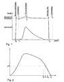
- Fig. 1 can be seen that at a time t 0, the tool is closed and at this time the (closing) force increases sharply.
- time t 1 the injection process is started. From this point onwards, the force with which the closing unit is locked increases until the so-called Auftreibkraft. (The lower curve in Fig. 1 shows in enlarged form the overlying the closing force pressure curve shape).
- the locking force adds to the closing force. The locking force usually tolerates 1 - 2% of the closing force.
- the clamping force decreases continuously again from a maximum point.
- time t 2 the tool is then opened.
- the closing force reduction is started even before reaching the so-called 1 bar line.
- the 1-bar line is marked with p1.
- the pressure curve of the cavity pressure reaches the 1 bar line at time t 1 .
- the closing force reduction is started. This time depends on the time t 1 , the pressure gradient of the cavity pressure, which is almost linear in the end and the time for the pressure reduction.
- the tool could be opened.
- the tool is then actually opened.
- the cycle time can thus be reduced in the region of the cooling phase by a prematurely initiated closure force reduction, thus increasing the efficiency of an injection molding process. become.
Landscapes
- Engineering & Computer Science (AREA)
- Manufacturing & Machinery (AREA)
- Mechanical Engineering (AREA)
- Injection Moulding Of Plastics Or The Like (AREA)
- Moulds For Moulding Plastics Or The Like (AREA)
Description
- Die vorliegende Erfindung betrifft ein Verfahren zur Durchführung des Schließkraftabbaus bei einer Schließeinheit einer Spritzgießmaschine.
- Auf die Wirtschaftlichkeit eines Spritzgießprozesses hat die Zykluszeit einen wesentlichen Einfluss. Ziel bei der wirtschaftlichen Produktion eines Formteiles ist es, die für diesen Ablauf benötigte Zykluszeit auf ein Minimum zu reduzieren. Dadurch kann eine möglichst hohe Ausstoßleistung erzielt werden.
- Die Verfahrensschritte, wie Werkzeug- und Aggregatbewegungen, Einspritzen, Nachdrücken, Kühlen sowie Dosieren sind feste Bestandteile eines jeden Zyklus. Die einzelnen Schritte laufen teilweise nacheinander ab, zum Teil überdecken sie sich zeitlich. Beispielsweise startet die Kühlzeit definitionsgemäß mit dem Beginn des Einspritzvorganges. Sie beinhaltet die komplette Nachdruckphase und endet schließlich mit dem Öffnungshub des Werkzeugs zur Entformung des fertigen Formteils. Nach der Nachdruckzeit beginnt die sogenannte Restkühlzeit. Die Kühlzeit eines spritzgegossenen Formteils beträgt meist mehr als 2/3 der gesamten Zykluszeit. Sie steigt mit dem Quadrat der Formteilwanddicke. In der Regel erstreckt sich die Kühlzeit über die Nachdruckphase hinaus, da das Formteil bis zum Abschluss der Nachdruckphase im Allgemeinen noch nicht hinreichend abgekühlt ist und somit für die Entformung noch nicht ausreichend dimensionsstabil ist. Mit dem Öffnen des Werkzeugs endet die Kühlzeit.
- Demnach wird die Kühlzeit im Allgemeinen in die Abschnitte Einspritzzeit, Nachdruckzeit und Restkühlzeit unterteilt. Zur Ermittlung der gesamten Kühlzeit müssen die einzelnen Abschnitte möglichst genau abgeschätzt werden. Die Nachdruckzeit lässt sich durch die Bestimmung der Siegelzeit abschätzen. Die Siegelzeit bezeichnet den Zeitpunkt, bis zu dem noch Material mittels Nachdruck in die Kavität nachgeschoben werden kann, d.h. bis der Anschnitt bzw. der Anguss des Formteils erstarrt ist. In der Regel reichen etwa 30 % der Kühlzeit aus, bis der Anguss eingefroren ist. Dies hängt jedoch insbesondere vom Material und von der Formteilgeometrie/-dicke ab. Nach Erreichen der Siegelzeit ist es nicht mehr möglich, den Nachdruck wirkungsvoll aufrecht zu erhalten.
- Wenn während des Formteilbildungsprozesses der Druck im Werkzeug auf Umgebungsdruck abgesunken ist, kann das Formteil meistens infolge mangelnder Formstabilität noch nicht entformt werden. Die Entformung eines thermoplastischen Bauteils kann erst auf einem niedrigeren Temperaturniveau geschehen, so dass das Formteil bis dahin weiter in der Werkzeugkavität heruntergekühlt werden muss. Allerdings ist es ab dem Erreichen des Umgebungsdruckes nicht mehr notwendig, den Schließdruck aufrechtzuerhalten.
- Die ab dem Erreichen des Siegelpunktes noch zusätzlich erforderliche Verweilzeit im Werkzeug bis zur Entformung wird Restkühlzeit genannt. Die Restkühlzeit ergibt sich somit aus der gesamten Kühlzeit abzüglich der Nachdruckzeit und der Einspritzzeit. Sie beginnt nach Ablauf der Nachdruckphase und wird an den Spritzgießmaschinen üblicherweise als Einstellparameter eingegeben.
- Um die Wirtschaftlichkeit der Fertigung zu erhöhen, muss geklärt werden, ob der Spritzgießzyklus Zeitreserven bietet, um die der Fertigungsprozess verkürzt werden kann.
- In diesem Zusammenhang hat man festgestellt, dass der Schließkraftabbau je nach Konstruktion und Betrieb der Schließeinheit einige Zeit in Anspruch nimmt. Startet man den Schließkraftabbau also erst dann, wenn der Umgebungsdruck in der Kavität erreicht ist und ab dem das Aufrechterhalten des Schließdruckes nicht mehr notwendig ist, so geht wertvolle Zeit verloren.
- Es ist bereits bekannt, die Oberflächentemperatur zur Festlegung der optimalen Kühlzeit zu nutzen, um nach Erreichen eines bestimmten Temperaturwertes das Werkzeug öffnen zu können. Allerdings ist man weiter auf die Einstellung und Abschätzung des Einrichters hinsichtlich der Gesamtzykluszeit angewiesen.
- Das Document
AT-B-384 772 - Aufgabe der vorliegenden Erfindung ist es, ein Verfahren zur Durchführung des Schließkraftabbaus bei einer Schließeinheit einer Spritzgießmaschine derart weiterzubilden, dass die Zykluszeit weiter optimiert wird.
- Diese Aufgabe wird durch die im Anspruch 1 angegebenen Merkmale verfahrensmäßig gelöst.
- Dabei ist ein Gedanke der vorliegenden Erfindung darin zu sehen, dass man die Zeit einkalkuliert, die der Schließdruckabbau benötigt und den Schließdruckabbau entsprechend vorzeitig startet, so dass die für den Schließdruckabbau benötigte Zeit nicht unnötig verloren geht. Allerdings kann der Schließdruckabbau nicht willkürlich gestartet werden. Zum einen muss natürlich die Geschwindigkeit bzw. die Zeitdauer bekannt sein, die der Schließdruckabbau benötigt (Durchschalten von Ventilen, Entspannung des Druckes in den Leitungen, Anlaufen von Elektromotoren, etc.). Zum anderen hängt die Gestattung der Einleitung des Schließdruckabbaus auch von den Produkt- und Materialeigenschaften ab, so nimmt die Kühlzeit für dicke Materialien im Quadrat zu, so dass der Zeitpunkt für den Schließkraftabbau maßgeblich von der Produktgeometrie abhängt. Beim Einrichten eines Spritzgießverfahrens werden erfindungsgemäß Druckkurven mittels eines an geeigneter Stelle im Werkzeug angeordneten Werkzeuginnendrucksensors ermittelt. Aus diesen Druckkurven wird eine Sollkurve abgeleitet und in der Maschinensteuerung hinterlegt. In Abhängigkeit von den Produkt- und Materialeigenschaften wird der Siegelpunkt bzw. der Punkt, ab dem der Schließdruck nicht mehr benötigt wird, ermittelt. Dieser Punkt kann beispielsweise die 1-bar-Linie sein, da dann von dem Produkt keine Kraft mehr auf das Werkzeug ausgeübt wird, als durch den normalen Luftdruck. Unter Einbeziehung der Abbaugeschwindigkeit des Schließdruckes kann dann ein Druck auf der Soll- bzw. Referenzkurve ermittelt werden, ab dem der Schließkraftdruckabbau begonnen werden kann.
- Beim zyklusweisen Betrieb der Spritzgießmaschine wird sodann der Ist-Druck durch den Werkzeuginnendrucksensor während der Kühlphase kontinuierlich ermittelt und der Druckkraftabbau insbesondere dann durchgeführt, wenn der Ist-Druck den auf der Soll-Druck-Kurve markierten Wert erreicht hat. Durch die Ermittlung des Siegelpunktes bzw. des Druckpunktes, ab dem ein Schließdruck nicht mehr vorliegen muss, kann der frühestmögliche Zeitpunkt für einen Druckkraftabbau ohne Qualitätseinbußen ermittelt werden.
- Die hinterlegte Soll-, Referenz- oder auch Masterkurve dient also zur Regelung des Schließkraftabbaus. Sie orientiert sich am gemessenen Ist-Wert und der zugrundeliegenden Abbaugeschwindigkeit des Kavitätsdruckes. Die Abbaugeschwindigkeit des Schließdruckes kann insbesondere auch als zeitliche Ableitung des Drucksignals gesehen werden, wobei der Druckabbau zum Ende der Kühlzeit näherungsweise einem linearen Verlauf nahe kommt. Anhand dieses Druckgradienten, der auch materialabhängig ist, kann die Einleitung des Schließkraftabbaus mitbestimmt werden.
- Insgesamt wird also mit dem Schließkraftabbau begonnen, bevor die 1-bar-Linie erreicht wird. Dies spart zusätzliche Zykluszeit.
- In den beigefügten Figuren ist dieser Zusammenhang nochmals deutlich gemacht. So zeigt
- Fig. 1
- ein Druckdiagramm für die Zuhaltekraft einer Schließeinheit während der Geschlossen-Phase und
- Fig. 2
- eine Druckkurve des Innendrucks in einer Werkzeugkavität während der Kühlphase.
- Aus
Fig. 1 kann man erkennen, dass bei einem Zeitpunkt t0 das Werkzeug geschlossen wird und zu diesem Zeitpunkt die (Schließ-)Kraft stark ansteigt. Beim Zeitpunkt t1 wird der Einspritzvorgang gestartet. Ab diesem Zeitpunkt nimmt die Kraft, mit der die Schließeinheit zugehalten wird, bis zur sog. Auftreibkraft zu. (Die untere Kurve inFig. 1 zeigt dabei in vergrößerter Form die über der Schließkraft liegende Druckkurvenform). Insgesamt addiert sich die Zuhaltekraft zur Schließkraft. Die Zuhaltekraft verträgt in der Regel 1 - 2 % der Schließkraft. Im unteren Bereich derFig. 1 , wo die Zuhaltekraft in vergrößerter Form dargestellt wird, sieht man, dass die Zuhaltekraft ab einem Maximalpunkt wieder kontinuierlich abfällt. Zum Zeitpunkt t2 wird das Werkzeug dann geöffnet. - Um nun in erfindungsgemäßer Weise die Zykluszeit optimal zu gestalten, wird bereits vor Erreichen der sogenannten 1-bar-Linie der Schließkraftabbau gestartet. In
Fig. 2 ist die 1-bar-Linie mit p1 gekennzeichnet. Die Druckkurve des Werkzeuginnendrucks erreicht die 1-bar-Linie zum Zeitpunkt t1. Bereits vor dem Zeitpunkt t1, nämlich zum Zeitpunkt t0 wird der Schließkraftabbau gestartet. Dieser Zeitpunkt hängt von dem Zeitpunkt t1, dem Druckgradienten des Werkzeuginnendrucks, der im Endbereich nahezu linear ist und der Zeitdauer für den Druckabbau ab. Zum Zeitpunkt tA könnte dann das Werkzeug geöffnet werden. Zum Zeitpunkt t2 wird das Werkzeug dann tatsächlich geöffnet. - Insgesamt kann somit im Bereich der Kühlphase durch einen vorzeitig eingeleiteten Schließkraftabbau die Zykluszeit verringert und damit die Effizienz eines Spritzgießprozesses erhöht. werden.
Claims (5)
- Verfahren zur Durchführung des Schließkraftabbaus bei einer Schließeinheit einer Spritzgießmaschine,
bei dem- beim Einrichten des Spritzgießverfahrens-- eine oder mehrere reale Druckkurven des Werkzeuginnendruckes während der Kühlphase ermittelt und daraus abgeleitet eine Sollkurve in der Maschinensteuerung hinterlegt werden,-- in Abhängigkeit von den Produkt- und Materialeigenschaften der Siegelpunkt auf der Druckkurve bestimmt wird,-- die Abbaugeschwindigkeit des Schließdruckes der Schließeinheit ermittelt wird,-- in Abhängigkeit vom Siegelpunkt und der Abbaugeschwindigkeit festgelegt wird, bei welchem Druck auf der Referenzkurve mit dem Schließkraftdruckkraftabbau begonnen wird und- beim zyklusweisen Betrieb der Spritzgießmaschine-- der Ist-Druck während der Kühlphase ermittelt wird und-- der Druckkraftabbau dann durchgeführt wird, wenn der Ist-Druck den bei der Einrichtung bestimmten Soll-Druck erreicht hat. - Verfahren nach Anspruch 1,
dadurch gekennzeichnet, dass
bei der Ermittlung der Abbaugeschwindigkeit des Druckes der Druckgradient verwendet wird. - Verfahren nach Anspruch 1 oder 2,
dadurch gekennzeichnet,
dass beim Schließdruckabbau miteinbezogen wird, wann die 1 bar Druck-Linie erreicht ist. - Verfahren nach Anspruch 3,
dadurch gekennzeichnet,
dass ein linearer Druckabbau zum Ende der Kühlzeit bei der Festlegung und Berechnung verwendet wird. - Verfahren nach einem der vorhergehenden Ansprüche,
dadurch gekennzeichnet,
dass der Siegeldruck unter Verwendung einer hinterlegten mathematischen Formel bestimmt wird, bei der definierte Parameter, wie Produktgröße, maximale Materialdicke und Materialart, eingegeben werden.
Applications Claiming Priority (1)
| Application Number | Priority Date | Filing Date | Title |
|---|---|---|---|
| DE102007029977A DE102007029977B4 (de) | 2007-06-28 | 2007-06-28 | Verfahren zur Durchführung des Schließkraftabbaus bei einer Schließeinheit einer Spritzgießmaschine |
Publications (2)
| Publication Number | Publication Date |
|---|---|
| EP2008791A1 EP2008791A1 (de) | 2008-12-31 |
| EP2008791B1 true EP2008791B1 (de) | 2009-12-23 |
Family
ID=39791216
Family Applications (1)
| Application Number | Title | Priority Date | Filing Date |
|---|---|---|---|
| EP08010851A Active EP2008791B1 (de) | 2007-06-28 | 2008-06-14 | Verfahren zur Durchführung des Schließkraftabbaus bei einer Schließeinheit einer Spritzgießmaschine |
Country Status (4)
| Country | Link |
|---|---|
| US (1) | US20090001624A1 (de) |
| EP (1) | EP2008791B1 (de) |
| AT (1) | ATE452740T1 (de) |
| DE (2) | DE102007029977B4 (de) |
Families Citing this family (2)
| Publication number | Priority date | Publication date | Assignee | Title |
|---|---|---|---|---|
| AT514836B1 (de) * | 2013-09-30 | 2015-06-15 | Engel Austria Gmbh | Verfahren zur Bestimmung eines Siegelpunktes |
| CN112959634B (zh) * | 2021-02-04 | 2022-07-26 | 北京化工大学 | 一种设定注塑机最优锁模力的方法 |
Family Cites Families (16)
| Publication number | Priority date | Publication date | Assignee | Title |
|---|---|---|---|---|
| JPS56146741A (en) * | 1980-04-18 | 1981-11-14 | Hitachi Ltd | Setting of holding time and system therefor |
| AT384772B (de) * | 1986-03-17 | 1988-01-11 | Cincinnati Milacron Austria | Verfahren zum herstellen von spritzgussteilen |
| DE3932960A1 (de) * | 1989-10-03 | 1991-04-11 | Battenfeld Gmbh | Verfahren zur herstellung von formteilen aus plastifizierbaren kunststoff-formmassen durch spritzgiessen |
| JPH03143613A (ja) * | 1989-10-31 | 1991-06-19 | Japan Steel Works Ltd:The | 射出成形における固化時間の同定方法及び装置 |
| WO1991008890A1 (en) * | 1989-12-08 | 1991-06-27 | Philips And Du Pont Optical Company | Apparatus and method for controlling an injection molding process producing a molded part |
| JPH04112024A (ja) * | 1990-09-03 | 1992-04-14 | Japan Steel Works Ltd:The | 射出成形機の型緩め方法およびその装置 |
| JPH0829557B2 (ja) * | 1992-04-28 | 1996-03-27 | 株式会社新潟鉄工所 | 射出成形機の型開き方法 |
| DE19525141C1 (de) * | 1995-07-11 | 1996-11-28 | Karl Hehl | Verfahren zur Regelung oder Steuerung einer Kunststoff-Spritzgießmaschine |
| JP3519511B2 (ja) * | 1995-07-27 | 2004-04-19 | ファナック株式会社 | 射出成形機の制御方法および装置 |
| JP3219268B2 (ja) * | 1998-03-31 | 2001-10-15 | 住友重機械工業株式会社 | 型締制御装置 |
| JP3423219B2 (ja) * | 1998-06-30 | 2003-07-07 | 株式会社名機製作所 | ディスク基板の射出成形機におけるモニタ方法及び成形作動制御装置 |
| US6430466B1 (en) * | 1999-08-23 | 2002-08-06 | General Electric Company | System for controlling clamp pressure in an automatic molding machine |
| US6572796B1 (en) * | 2000-10-27 | 2003-06-03 | General Electric Company | Method of predicting optimal injection molding cycle time |
| DE10114228A1 (de) * | 2001-03-22 | 2002-10-02 | Frey Juergen | Verfahren zum Regeln der Schwindung von Spritzteilen |
| JP4146381B2 (ja) * | 2004-03-31 | 2008-09-10 | 日精樹脂工業株式会社 | トグル式型締装置の型締力補正方法 |
| DE102004043300A1 (de) * | 2004-09-08 | 2006-03-09 | Krauss-Maffei Kunststofftechnik Gmbh | Verfahren zum Betreiben einer Spritzgießmaschine |
-
2007
- 2007-06-28 DE DE102007029977A patent/DE102007029977B4/de not_active Expired - Fee Related
-
2008
- 2008-06-14 EP EP08010851A patent/EP2008791B1/de active Active
- 2008-06-14 DE DE502008000263T patent/DE502008000263D1/de active Active
- 2008-06-14 AT AT08010851T patent/ATE452740T1/de active
- 2008-06-30 US US12/164,723 patent/US20090001624A1/en not_active Abandoned
Also Published As
| Publication number | Publication date |
|---|---|
| EP2008791A1 (de) | 2008-12-31 |
| DE502008000263D1 (de) | 2010-02-04 |
| US20090001624A1 (en) | 2009-01-01 |
| ATE452740T1 (de) | 2010-01-15 |
| DE102007029977A1 (de) | 2009-01-02 |
| DE102007029977B4 (de) | 2009-09-24 |
Similar Documents
| Publication | Publication Date | Title |
|---|---|---|
| EP3661720B2 (de) | Verfahren zur variothermen temperierung von spritzgiesswerkzeugen | |
| DE102015000219B4 (de) | Formklemmkrafteinstellvorrichtung und -Verfahren für eine Spritzgießmaschine | |
| DE102015114845B4 (de) | Verfahren und Gerät zum Spritzgießen von Kunststoffmaterialien | |
| DE112011100051T5 (de) | Gießverfahren einer Spritzgießmaschine | |
| DE102018107870A1 (de) | Verfahren, Vorrichtung und Presse zum Spritzgießen von Kunststoff | |
| DE68919462T2 (de) | Verfahren und Vorrichtung zum Regeln eines Druckgiessvorganges durch Steuerung der Bewegung des Druckkolbens. | |
| US11446850B2 (en) | Method and apparatus for injection molding of plastic materials | |
| AT514847B1 (de) | Verfahren zur Bestimmung eines Sollwerts für einen Einstellparameter | |
| EP3071389B1 (de) | Verfahren zum regeln der füllung von zumindest einer kavität | |
| WO2012175287A1 (de) | Vorrichtung und verfahren zur temperierung einer druckgussform | |
| DE102007029977B4 (de) | Verfahren zur Durchführung des Schließkraftabbaus bei einer Schließeinheit einer Spritzgießmaschine | |
| US10144165B2 (en) | Method and apparatus for the injection molding of plastic materials | |
| WO2010017940A1 (de) | Verfahren zur regeln bzw. steuern von funktionen einer spritzgiessmaschine | |
| DE3608973A1 (de) | Verfahren und vorrichtung zum steuern der verdichtungsphase beim spritzgiessen thermoplastischer formmassen | |
| DE3501846A1 (de) | Verfahren zum regeln des spritzgiessvorgangs einer spritzgussmaschine sowie vorrichtung zur durchfuehrung des verfahrens | |
| AT517832B1 (de) | Verfahren zum Ermitteln der Lage eines Einleitungspunktes einer Auftreibkraft | |
| EP1650004B1 (de) | Verfahren zum Spritzgiessen mit einem Prägeablauf | |
| AT514836A1 (de) | Verfahren zur Bestimmung eines Siegelpunktes | |
| AT501951B1 (de) | Verfahren zum spritzgiessen von kunststoffteilen | |
| EP2615518B1 (de) | Verfahren zur Aufheizung und Regelung der Temperatur eines mit einem flüssigen und/oder dampfförmigen Wärmeträger beheizten Fertigungswerkzeuges | |
| EP2298530A2 (de) | Vorrichtung und Verfahren zur Temperierung eines Spritzgießwerkzeugs | |
| DE102005052997A1 (de) | Prozeßsteuerung für Gas-unterstützte Spritzgußanwendungen | |
| DE10357365B4 (de) | Druckgießvorrichtung und Verfahren zum Druckgießen mit einem definierten Forminnendruck | |
| DE202009012749U1 (de) | Vorrichtung zur Temperierung eines Spritzgießwerkzeugs | |
| WO2011042153A1 (de) | Verfahren zur regelung der herstellung eines produktes |
Legal Events
| Date | Code | Title | Description |
|---|---|---|---|
| PUAI | Public reference made under article 153(3) epc to a published international application that has entered the european phase |
Free format text: ORIGINAL CODE: 0009012 |
|
| AK | Designated contracting states |
Kind code of ref document: A1 Designated state(s): AT BE BG CH CY CZ DE DK EE ES FI FR GB GR HR HU IE IS IT LI LT LU LV MC MT NL NO PL PT RO SE SI SK TR |
|
| AX | Request for extension of the european patent |
Extension state: AL BA MK RS |
|
| 17P | Request for examination filed |
Effective date: 20081219 |
|
| GRAP | Despatch of communication of intention to grant a patent |
Free format text: ORIGINAL CODE: EPIDOSNIGR1 |
|
| AKX | Designation fees paid |
Designated state(s): AT BE BG CH CY CZ DE DK EE ES FI FR GB GR HR HU IE IS IT LI LT LU LV MC MT NL NO PL PT RO SE SI SK TR |
|
| GRAS | Grant fee paid |
Free format text: ORIGINAL CODE: EPIDOSNIGR3 |
|
| GRAA | (expected) grant |
Free format text: ORIGINAL CODE: 0009210 |
|
| AK | Designated contracting states |
Kind code of ref document: B1 Designated state(s): AT BE BG CH CY CZ DE DK EE ES FI FR GB GR HR HU IE IS IT LI LT LU LV MC MT NL NO PL PT RO SE SI SK TR |
|
| REG | Reference to a national code |
Ref country code: GB Ref legal event code: FG4D Free format text: NOT ENGLISH |
|
| REG | Reference to a national code |
Ref country code: CH Ref legal event code: EP |
|
| REG | Reference to a national code |
Ref country code: IE Ref legal event code: FG4D |
|
| REF | Corresponds to: |
Ref document number: 502008000263 Country of ref document: DE Date of ref document: 20100204 Kind code of ref document: P |
|
| REG | Reference to a national code |
Ref country code: DE Ref legal event code: R096 Ref document number: 502008000263 Country of ref document: DE Effective date: 20100204 |
|
| REG | Reference to a national code |
Ref country code: NL Ref legal event code: VDEP Effective date: 20091223 |
|
| PG25 | Lapsed in a contracting state [announced via postgrant information from national office to epo] |
Ref country code: SE Free format text: LAPSE BECAUSE OF FAILURE TO SUBMIT A TRANSLATION OF THE DESCRIPTION OR TO PAY THE FEE WITHIN THE PRESCRIBED TIME-LIMIT Effective date: 20091223 Ref country code: FI Free format text: LAPSE BECAUSE OF FAILURE TO SUBMIT A TRANSLATION OF THE DESCRIPTION OR TO PAY THE FEE WITHIN THE PRESCRIBED TIME-LIMIT Effective date: 20091223 Ref country code: NO Free format text: LAPSE BECAUSE OF FAILURE TO SUBMIT A TRANSLATION OF THE DESCRIPTION OR TO PAY THE FEE WITHIN THE PRESCRIBED TIME-LIMIT Effective date: 20100323 Ref country code: LT Free format text: LAPSE BECAUSE OF FAILURE TO SUBMIT A TRANSLATION OF THE DESCRIPTION OR TO PAY THE FEE WITHIN THE PRESCRIBED TIME-LIMIT Effective date: 20091223 |
|
| LTIE | Lt: invalidation of european patent or patent extension |
Effective date: 20091223 |
|
| PG25 | Lapsed in a contracting state [announced via postgrant information from national office to epo] |
Ref country code: LV Free format text: LAPSE BECAUSE OF FAILURE TO SUBMIT A TRANSLATION OF THE DESCRIPTION OR TO PAY THE FEE WITHIN THE PRESCRIBED TIME-LIMIT Effective date: 20091223 Ref country code: HR Free format text: LAPSE BECAUSE OF FAILURE TO SUBMIT A TRANSLATION OF THE DESCRIPTION OR TO PAY THE FEE WITHIN THE PRESCRIBED TIME-LIMIT Effective date: 20091223 Ref country code: SI Free format text: LAPSE BECAUSE OF FAILURE TO SUBMIT A TRANSLATION OF THE DESCRIPTION OR TO PAY THE FEE WITHIN THE PRESCRIBED TIME-LIMIT Effective date: 20091223 Ref country code: PL Free format text: LAPSE BECAUSE OF FAILURE TO SUBMIT A TRANSLATION OF THE DESCRIPTION OR TO PAY THE FEE WITHIN THE PRESCRIBED TIME-LIMIT Effective date: 20091223 |
|
| REG | Reference to a national code |
Ref country code: IE Ref legal event code: FD4D |
|
| PG25 | Lapsed in a contracting state [announced via postgrant information from national office to epo] |
Ref country code: ES Free format text: LAPSE BECAUSE OF FAILURE TO SUBMIT A TRANSLATION OF THE DESCRIPTION OR TO PAY THE FEE WITHIN THE PRESCRIBED TIME-LIMIT Effective date: 20100403 Ref country code: EE Free format text: LAPSE BECAUSE OF FAILURE TO SUBMIT A TRANSLATION OF THE DESCRIPTION OR TO PAY THE FEE WITHIN THE PRESCRIBED TIME-LIMIT Effective date: 20091223 Ref country code: NL Free format text: LAPSE BECAUSE OF FAILURE TO SUBMIT A TRANSLATION OF THE DESCRIPTION OR TO PAY THE FEE WITHIN THE PRESCRIBED TIME-LIMIT Effective date: 20091223 Ref country code: RO Free format text: LAPSE BECAUSE OF FAILURE TO SUBMIT A TRANSLATION OF THE DESCRIPTION OR TO PAY THE FEE WITHIN THE PRESCRIBED TIME-LIMIT Effective date: 20091223 Ref country code: IS Free format text: LAPSE BECAUSE OF FAILURE TO SUBMIT A TRANSLATION OF THE DESCRIPTION OR TO PAY THE FEE WITHIN THE PRESCRIBED TIME-LIMIT Effective date: 20100423 Ref country code: BG Free format text: LAPSE BECAUSE OF FAILURE TO SUBMIT A TRANSLATION OF THE DESCRIPTION OR TO PAY THE FEE WITHIN THE PRESCRIBED TIME-LIMIT Effective date: 20100323 |
|
| PG25 | Lapsed in a contracting state [announced via postgrant information from national office to epo] |
Ref country code: CZ Free format text: LAPSE BECAUSE OF FAILURE TO SUBMIT A TRANSLATION OF THE DESCRIPTION OR TO PAY THE FEE WITHIN THE PRESCRIBED TIME-LIMIT Effective date: 20091223 Ref country code: SK Free format text: LAPSE BECAUSE OF FAILURE TO SUBMIT A TRANSLATION OF THE DESCRIPTION OR TO PAY THE FEE WITHIN THE PRESCRIBED TIME-LIMIT Effective date: 20091223 |
|
| PG25 | Lapsed in a contracting state [announced via postgrant information from national office to epo] |
Ref country code: IE Free format text: LAPSE BECAUSE OF FAILURE TO SUBMIT A TRANSLATION OF THE DESCRIPTION OR TO PAY THE FEE WITHIN THE PRESCRIBED TIME-LIMIT Effective date: 20091223 Ref country code: CY Free format text: LAPSE BECAUSE OF FAILURE TO SUBMIT A TRANSLATION OF THE DESCRIPTION OR TO PAY THE FEE WITHIN THE PRESCRIBED TIME-LIMIT Effective date: 20091223 Ref country code: GR Free format text: LAPSE BECAUSE OF FAILURE TO SUBMIT A TRANSLATION OF THE DESCRIPTION OR TO PAY THE FEE WITHIN THE PRESCRIBED TIME-LIMIT Effective date: 20100324 |
|
| PLBE | No opposition filed within time limit |
Free format text: ORIGINAL CODE: 0009261 |
|
| STAA | Information on the status of an ep patent application or granted ep patent |
Free format text: STATUS: NO OPPOSITION FILED WITHIN TIME LIMIT |
|
| 26N | No opposition filed |
Effective date: 20100924 |
|
| BERE | Be: lapsed |
Owner name: SUMITOMO (SHI) DEMAG PLASTICS MACHINERY G.M.B.H. Effective date: 20100630 |
|
| REG | Reference to a national code |
Ref country code: DE Ref legal event code: R097 Ref document number: 502008000263 Country of ref document: DE Effective date: 20100924 |
|
| PG25 | Lapsed in a contracting state [announced via postgrant information from national office to epo] |
Ref country code: MC Free format text: LAPSE BECAUSE OF NON-PAYMENT OF DUE FEES Effective date: 20100630 Ref country code: DK Free format text: LAPSE BECAUSE OF FAILURE TO SUBMIT A TRANSLATION OF THE DESCRIPTION OR TO PAY THE FEE WITHIN THE PRESCRIBED TIME-LIMIT Effective date: 20091223 |
|
| REG | Reference to a national code |
Ref country code: FR Ref legal event code: ST Effective date: 20110228 |
|
| PG25 | Lapsed in a contracting state [announced via postgrant information from national office to epo] |
Ref country code: IT Free format text: LAPSE BECAUSE OF FAILURE TO SUBMIT A TRANSLATION OF THE DESCRIPTION OR TO PAY THE FEE WITHIN THE PRESCRIBED TIME-LIMIT Effective date: 20091223 |
|
| PG25 | Lapsed in a contracting state [announced via postgrant information from national office to epo] |
Ref country code: MT Free format text: LAPSE BECAUSE OF FAILURE TO SUBMIT A TRANSLATION OF THE DESCRIPTION OR TO PAY THE FEE WITHIN THE PRESCRIBED TIME-LIMIT Effective date: 20091223 |
|
| PG25 | Lapsed in a contracting state [announced via postgrant information from national office to epo] |
Ref country code: FR Free format text: LAPSE BECAUSE OF NON-PAYMENT OF DUE FEES Effective date: 20100630 |
|
| PG25 | Lapsed in a contracting state [announced via postgrant information from national office to epo] |
Ref country code: BE Free format text: LAPSE BECAUSE OF NON-PAYMENT OF DUE FEES Effective date: 20100630 |
|
| PG25 | Lapsed in a contracting state [announced via postgrant information from national office to epo] |
Ref country code: PT Free format text: LAPSE BECAUSE OF FAILURE TO SUBMIT A TRANSLATION OF THE DESCRIPTION OR TO PAY THE FEE WITHIN THE PRESCRIBED TIME-LIMIT Effective date: 20100523 Ref country code: HU Free format text: LAPSE BECAUSE OF FAILURE TO SUBMIT A TRANSLATION OF THE DESCRIPTION OR TO PAY THE FEE WITHIN THE PRESCRIBED TIME-LIMIT Effective date: 20100624 Ref country code: LU Free format text: LAPSE BECAUSE OF NON-PAYMENT OF DUE FEES Effective date: 20100614 |
|
| PG25 | Lapsed in a contracting state [announced via postgrant information from national office to epo] |
Ref country code: TR Free format text: LAPSE BECAUSE OF FAILURE TO SUBMIT A TRANSLATION OF THE DESCRIPTION OR TO PAY THE FEE WITHIN THE PRESCRIBED TIME-LIMIT Effective date: 20091223 |
|
| REG | Reference to a national code |
Ref country code: CH Ref legal event code: PL |
|
| REG | Reference to a national code |
Ref country code: CH Ref legal event code: PL |
|
| GBPC | Gb: european patent ceased through non-payment of renewal fee |
Effective date: 20120614 |
|
| PG25 | Lapsed in a contracting state [announced via postgrant information from national office to epo] |
Ref country code: CH Free format text: LAPSE BECAUSE OF NON-PAYMENT OF DUE FEES Effective date: 20120630 Ref country code: LI Free format text: LAPSE BECAUSE OF NON-PAYMENT OF DUE FEES Effective date: 20120630 Ref country code: GB Free format text: LAPSE BECAUSE OF NON-PAYMENT OF DUE FEES Effective date: 20120614 |
|
| P01 | Opt-out of the competence of the unified patent court (upc) registered |
Effective date: 20230526 |
|
| PGFP | Annual fee paid to national office [announced via postgrant information from national office to epo] |
Ref country code: AT Payment date: 20250624 Year of fee payment: 18 |
|
| PGFP | Annual fee paid to national office [announced via postgrant information from national office to epo] |
Ref country code: DE Payment date: 20250815 Year of fee payment: 18 |