EP2008835A1 - Rad mit ausbaubarer Speiche aus Verbundmaterial - Google Patents
Rad mit ausbaubarer Speiche aus Verbundmaterial Download PDFInfo
- Publication number
- EP2008835A1 EP2008835A1 EP08010801A EP08010801A EP2008835A1 EP 2008835 A1 EP2008835 A1 EP 2008835A1 EP 08010801 A EP08010801 A EP 08010801A EP 08010801 A EP08010801 A EP 08010801A EP 2008835 A1 EP2008835 A1 EP 2008835A1
- Authority
- EP
- European Patent Office
- Prior art keywords
- spoke
- radius
- wheel
- wheel according
- hub
- Prior art date
- Legal status (The legal status is an assumption and is not a legal conclusion. Google has not performed a legal analysis and makes no representation as to the accuracy of the status listed.)
- Withdrawn
Links
- 239000002131 composite material Substances 0.000 title claims abstract description 44
- 230000002441 reversible effect Effects 0.000 claims abstract description 16
- 239000000835 fiber Substances 0.000 claims description 10
- 230000007704 transition Effects 0.000 claims description 6
- 230000032798 delamination Effects 0.000 claims description 3
- 238000005096 rolling process Methods 0.000 claims 1
- 238000013037 co-molding Methods 0.000 abstract 1
- 238000000465 moulding Methods 0.000 description 10
- 229920000049 Carbon (fiber) Polymers 0.000 description 7
- 239000004917 carbon fiber Substances 0.000 description 7
- 229920000297 Rayon Polymers 0.000 description 6
- 239000002964 rayon Substances 0.000 description 6
- 238000004519 manufacturing process Methods 0.000 description 5
- 239000000463 material Substances 0.000 description 4
- 239000002184 metal Substances 0.000 description 3
- 238000000034 method Methods 0.000 description 3
- 238000005452 bending Methods 0.000 description 2
- 239000011159 matrix material Substances 0.000 description 2
- 239000012768 molten material Substances 0.000 description 2
- 229920002994 synthetic fiber Polymers 0.000 description 2
- DOSMHBDKKKMIEF-UHFFFAOYSA-N 2-[3-(diethylamino)-6-diethylazaniumylidenexanthen-9-yl]-5-[3-[3-[4-(1-methylindol-3-yl)-2,5-dioxopyrrol-3-yl]indol-1-yl]propylsulfamoyl]benzenesulfonate Chemical compound C1=CC(=[N+](CC)CC)C=C2OC3=CC(N(CC)CC)=CC=C3C(C=3C(=CC(=CC=3)S(=O)(=O)NCCCN3C4=CC=CC=C4C(C=4C(NC(=O)C=4C=4C5=CC=CC=C5N(C)C=4)=O)=C3)S([O-])(=O)=O)=C21 DOSMHBDKKKMIEF-UHFFFAOYSA-N 0.000 description 1
- 238000004026 adhesive bonding Methods 0.000 description 1
- 238000004873 anchoring Methods 0.000 description 1
- 230000000295 complement effect Effects 0.000 description 1
- 230000009365 direct transmission Effects 0.000 description 1
- 238000009826 distribution Methods 0.000 description 1
- 229940082150 encore Drugs 0.000 description 1
- 230000006355 external stress Effects 0.000 description 1
- 238000003754 machining Methods 0.000 description 1
- VNWKTOKETHGBQD-UHFFFAOYSA-N methane Chemical compound C VNWKTOKETHGBQD-UHFFFAOYSA-N 0.000 description 1
- 239000002952 polymeric resin Substances 0.000 description 1
- 230000002787 reinforcement Effects 0.000 description 1
- 229920005989 resin Polymers 0.000 description 1
- 239000011347 resin Substances 0.000 description 1
- 230000000717 retained effect Effects 0.000 description 1
- 229920003002 synthetic resin Polymers 0.000 description 1
- 239000012815 thermoplastic material Substances 0.000 description 1
- 229920001187 thermosetting polymer Polymers 0.000 description 1
- 238000004804 winding Methods 0.000 description 1
Images


Classifications
-
- B—PERFORMING OPERATIONS; TRANSPORTING
- B60—VEHICLES IN GENERAL
- B60B—VEHICLE WHEELS; CASTORS; AXLES FOR WHEELS OR CASTORS; INCREASING WHEEL ADHESION
- B60B1/00—Spoked wheels; Spokes thereof
- B60B1/003—Spoked wheels; Spokes thereof specially adapted for bicycles
-
- B—PERFORMING OPERATIONS; TRANSPORTING
- B60—VEHICLES IN GENERAL
- B60B—VEHICLE WHEELS; CASTORS; AXLES FOR WHEELS OR CASTORS; INCREASING WHEEL ADHESION
- B60B1/00—Spoked wheels; Spokes thereof
- B60B1/02—Wheels with wire or other tension spokes
- B60B1/0261—Wheels with wire or other tension spokes characterised by spoke form
- B60B1/0284—Wheels with wire or other tension spokes characterised by spoke form the spoke being threaded at both ends
-
- B—PERFORMING OPERATIONS; TRANSPORTING
- B60—VEHICLES IN GENERAL
- B60B—VEHICLE WHEELS; CASTORS; AXLES FOR WHEELS OR CASTORS; INCREASING WHEEL ADHESION
- B60B1/00—Spoked wheels; Spokes thereof
- B60B1/02—Wheels with wire or other tension spokes
- B60B1/04—Attaching spokes to rim or hub
- B60B1/041—Attaching spokes to rim or hub of bicycle wheels
-
- B—PERFORMING OPERATIONS; TRANSPORTING
- B60—VEHICLES IN GENERAL
- B60B—VEHICLE WHEELS; CASTORS; AXLES FOR WHEELS OR CASTORS; INCREASING WHEEL ADHESION
- B60B1/00—Spoked wheels; Spokes thereof
- B60B1/02—Wheels with wire or other tension spokes
- B60B1/04—Attaching spokes to rim or hub
- B60B1/042—Attaching spokes to hub
-
- B—PERFORMING OPERATIONS; TRANSPORTING
- B60—VEHICLES IN GENERAL
- B60B—VEHICLE WHEELS; CASTORS; AXLES FOR WHEELS OR CASTORS; INCREASING WHEEL ADHESION
- B60B21/00—Rims
- B60B21/06—Rims characterised by means for attaching spokes, i.e. spoke seats
- B60B21/062—Rims characterised by means for attaching spokes, i.e. spoke seats for bicycles
-
- B—PERFORMING OPERATIONS; TRANSPORTING
- B60—VEHICLES IN GENERAL
- B60B—VEHICLE WHEELS; CASTORS; AXLES FOR WHEELS OR CASTORS; INCREASING WHEEL ADHESION
- B60B5/00—Wheels, spokes, disc bodies, rims, hubs, wholly or predominantly made of non-metallic material
- B60B5/02—Wheels, spokes, disc bodies, rims, hubs, wholly or predominantly made of non-metallic material made of synthetic material
-
- B—PERFORMING OPERATIONS; TRANSPORTING
- B60—VEHICLES IN GENERAL
- B60B—VEHICLE WHEELS; CASTORS; AXLES FOR WHEELS OR CASTORS; INCREASING WHEEL ADHESION
- B60B1/00—Spoked wheels; Spokes thereof
- B60B1/02—Wheels with wire or other tension spokes
- B60B1/0261—Wheels with wire or other tension spokes characterised by spoke form
- B60B1/0276—Wheels with wire or other tension spokes characterised by spoke form the spoke being crooked in the middle and having double length
Definitions
- the invention relates to the field of spoke wheels made of composite material.
- Such rays have the advantage of being lighter and more resistant in comparison with the more conventional rays made of metal.
- the composite material spokes have the disadvantage of attachment to the hub and the rim which is more complicated, due to the nature of the composite materials. Indeed, taking the example of a radius of composite material in the form of carbon fibers embedded in a resinous matrix, it is found that such a fibrous radius does not lend itself to simple threading operations and deformations applicable to a metal spoke to make its ends connectable to the hub and the rim.
- a known solution for fixing a radius of composite material to the rim is to secure the spoke with the rim by applying a common molding process.
- the disadvantage of this method of assembly of the spoke and the rim appears during the breaking of the radius, for example by fatigue.
- the wheel can not be repaired since the spoke was irreversibly fixed to the rim during molding. It is necessary to replace the entire wheel, which is very expensive.
- the document FR 2 707 559 A1 discloses a metal spoke or composite material connected to the hub by its inner end removably.
- the connection is provided by a threaded end piece comprising two parallel walls defining a yoke forming a central housing in which is engaged and brazed, glued or welded the corresponding end of the spoke to secure said end piece to the radius.
- the object of the invention is to provide a radius of composite material with a device allowing a reversible connection between a radius of composite material and the wheel (rim, hub) of the known type of the aforementioned document FR 2 707 559 A1 .
- Another objective is to improve the connection especially with respect to the connection devices already known.
- Another object of the invention is to provide a radius whose manufacture is simplified with respect to the known radius of the document FR 2 707 559 A1 . Indeed, the solution according to this document, with an end piece, introduces an additional step during the manufacture of the beam, namely the step of bonding the end piece to the rest of the spoke.
- Another object of the invention is to provide a radius of composite material that can be easily replaced in case of rupture when used within a wheel.
- An object of the invention is also to build, using rays of composite material, an adjustable and repairable wheel.
- a wheel comprising at least one radius of composite material, characterized in that the spoke comprises a connecting device allowing a reversible connection with the wheel, and in that said connecting device is incorporated at least partially inside the radius by overmolding.
- spoke can be attached to the wheel (rim, hub) being easily removable or detachable when needed. This need may occur, for example, if the spoke breaks and needs to be replaced.
- the radius is a double radius, namely a radius extending substantially over the entire diameter of an associated wheel.
- the spoke according to the invention is adapted to be fixed by its two ends to a wheel rim, while its central portion is adapted to be fixed to the hub.
- the reversible connection device can therefore be arranged at the central part of the radius.
- the connecting device is incorporated at least in part by overmolding in the radius makes the connection between these two elements stronger and more reliable.
- the connecting device is more or less surrounded or framed by the composite material which maximizes the fixing surface between the device and the material.
- the device is integrated in the radius when molding it.
- the composite material and the at least partially implanted bonding device therein are placed together in a mold to be shaped and to undergo a temperature rise. After the molding operation, the connecting device is well bonded, at least partially, within the radius.
- the connecting device is inserted and held between two longitudinal outer surfaces of the spoke.
- the connecting device may be covered by the radius, either above and below, or on both sides, the cover being preferably partial, but may also be total.
- the connecting device is a wafer inserted between composite layers of the radius.
- the spoke has a superposition of two composite layers on one side of the wafer. This reduces the risk of delamination of two layers during assembly of the radius and therefore the risk of breakage, especially in case of bending thereof. Moreover, the covering which is necessary for the assembly of the spoke, is thus carried out in the central zone (and symmetrically) of the spoke, which does not induce unbalance with respect to the wheel.
- the wafer may comprise a longitudinal groove for accommodating at least one composite layer of the radius.
- the surface of the composite layer or layers arranged in the groove is flush with the outer surface of the wafer.
- the two superimposed composite layers can be housed in a first deeper groove of the plate defining a housing adapted to said composite layers, a third composite layer can be housed in a second groove less deep.
- the composite layers near the wafer may be surrounded by a strapping to prevent delamination.
- the spoke has a transition zone between the wafer and the composite layers in the form of molten material.
- the wafer may be flat, i.e. parallelepiped, or have two parts, one being inclined at an angle to the other, so as to form a kind of chevron.
- the wafer has an elliptical shape and comprises a pin for connecting with the hub.
- the connecting device may be a stepped pin, instead of a wafer.
- the pin is adapted to be housed in a hole of a flange of the hub.
- the connecting device can also be a threaded tube.
- connection device in the form of a pin plate, pin or tapped tube
- this device is incorporated in such a manner in the radius that the fibers of the composite material enclose or surround, that is to say that the fibers are not interrupted by the device, but only deviated.
- the connecting device may have a rough surface, preferably obtained by sanding, for improving the grip between the device and the spoke.
- the invention also relates to a wheel having at least one radius according to any one of the preceding embodiments.
- the material used for the rays is assumed to be carbon fibers embedded in a polymer resin matrix. Nevertheless, this is not limiting, and the rays can be made from any other composite material.
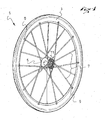
- the figure 1 gives an overview of a spoked wheel 1 according to the invention.
- the wheel 1 comprises a rim 3, a hub 5 and spokes 7 connecting the rim to the hub.
- the spokes 7 are in the form of double spokes, that is to say that they extend substantially over the entire diameter of the wheel, each of their ends 9 being connected to the rim 3 , their central part 11 being linked hub 5. It may also be simple spokes as will be seen later in connection with the figures 11 and 15 .
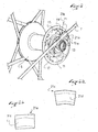
- figure 2 shows in detail the central part 11 of one of the double spokes 7.
- a plate 13 integrated in the central portion 11 of the spoke 7 which is housed in one of several housing 15 complementary shape to that of the wafer, in this case substantially rectangular, arranged in the flange 17 of the hub 5, the housing forming stops opposing the removal of the wafer especially when the spokes are under tension.
- the wafer 13 is substantially of rectangular or parallelepipedal shape and has two substantially square portions 19 and 21 whose upper faces 19a, 21a are inclined with respect to each other forming a kind of chevron, while the lower face 21 b is common and flat.
- the two parts 19, 21 may be constituted by a single piece 21 c chevron having a chevron groove 21 d (cf. figure 2a ) or a piece 21 e of rectangular shape having such a chevron 21f machining (cf. figure 2b ).
- the spokes 7 are embedded in the grooves 21d, 21f.
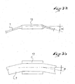
- the Figures 3a and 3b represent the two inclination angles ⁇ and ⁇ of the radii 7.
- the radii 7 are molded according to these two angles, ⁇ corresponding to "the umbrella angle” with respect to the plane of the wheel and ⁇ corresponding to the angle of traction .
- FIG. 4a to 4c show in detail a plate 13 according to another embodiment.
- This wafer 13 differs in fact slightly from the wafer shown in FIG. figure 2 , in that it is a flat plate having no inclination between its two parts.
- the plate 13 is made in such a way that it has large areas for bonding with the radius 7.
- the figure 4a is a longitudinal sectional view of the central portion 11 of the spoke 7 at the wafer.
- the radius 7 consists of three layers of composite material 23, 25 and 27.
- the layer 23 envelops the wafer 13 from one end to the other of the radius 7, while the layers 25 and 27 start from a end of the spoke 7, pass over the plate 13 and each stop at one of the two ends of the wafer 13.
- the layers 25 and 27 are superimposed at the upper surface of the wafer 13.
- the plate 13 is inserted and held between two longitudinal outer surfaces 33, 35 of the radius 7.
- the figure 4b is a cross-sectional view of the central portion 11 of the radius according to line IVb - IVb of the figure 4a .
- the layer 23 is in turn in a second groove 31 and through longitudinal opening in the underside of said wafer.
- the grooves are made in such a way that the surface of the layers is flush with that of the wafer. Therefore, the groove 31 is shallower than the groove 29.
- the two layers 25 and 27 are superimposed on the upper face 37 of the wafer 13. It could also be said that the wafer 13 has two longitudinal grooves of rectangular section 29, 31 for housing layers, composites.
- the figure 4c illustrates the possibility of adding a decorative layer 41 over the wafer 13.
- the color of this decorative layer 41 is for example the same as that of the flange 17, in order to obtain a pleasant aesthetic impression.
- This layer may be provided with a sufficient thickness to resume gluing efforts and increase the hold thereof.
- FIGS 5a and 5b show an example of connection between the wafer 13 and the composite layers of the radius 7 which differs slightly from that of the Figures 4a to 4c .
- a transition zone 43 of molten material between the wafer 13 and the layers of composite material is provided. This transition zone can improve the bond between the wafer 13 and the composite layers by reducing the risk of detachment of the layers of the wafer.
- the transition zone 43 is obtained by the addition of a rod or square of synthetic material and especially of thermoplastic material, such as 45 in the gap between the layers 23, 25, 27 and the plate 13 before molding.
- the ring 45 is melted during the molding of the assembly of the spoke 7 and the wafer 13.
- figure 5a shows the rod 45 inserted before the molding
- the figure 5b shows the result obtained after molding.
- the figure 5c shows an embodiment in which the plate 13 itself has a generally parallelepiped shape provided with two triangular ends forming said transition zones, which in this case do not melt during molding.
- the figure 6 shows a possibility of improvement of the bonding between the wafer 13 and the spoke 7. This improvement is done by straps 47 in unidirectional carbon fibers wound at each end of the wafer 13.
- FIGs 7a to 7c show an alternative means of attachment between the hub 5 and the spoke 7.
- the connection is provided, not by a plate, but by a shoulder pin 49.
- figure 7a is a longitudinal partial section of the central portion 11 of the radius 7.
- the figure 7b is a top view of this central portion 11.
- the Figure 7c shows how the pin 49 allows the reversible attachment of the spoke 7 to the flange 17 of the hub 5.
- the pin 49 does not interrupt or does not pierce the carbon fibers extending from one end to the other of the radius 7. Indeed, during the molding of the radius and pin assembly, the fibers are spread and draped around the pin.
- FIGs 8a to 8c show another variant of connecting means between the hub 5 and the central portion 11 of the spoke 7.
- the connecting means is a smooth tube end 55 inserted into the spoke in a manner similar to the pin 49.
- figure 8a is a longitudinal partial section of the central portion 11 of the radius 7.
- the figure 8b is a top view of this central portion 11.
- the figure 8a shows how the tube 55 allows, by means of a screw 57, the reversible attachment by screwing the spoke 7 to the flange 17 of the hub 5 which has a threaded hole 17a.
- the pin 49 the carbon fibers are not interrupted by the tube 55 but draped around it which gives rise to a bulge 59.
- Figures 9a to 9d show yet another variant of the connecting means.
- the connecting means is a kind of elliptical wafer 61 with a pin 63.
- the elliptical shape provides a large bonding surface between the wafer 61 and the spoke 7.
- the pin 63 allows the connection with the hub 5.
- FIGs 9a to 9c are, respectively, a side, top and bottom view of the central portion 11 of the radius 7.
- the figure 9d shows how the wafer 61 allows the reversible hooking of the spoke 7 to the flange 17 of the hub 5.
- the upper face 65 and the lower face 67 of the wafer 61 are provided with longitudinal grooves 65a, 67a, respectively, for accommodating the composite layers, similarly to the wafer 13 of the Figures 4a to 4c .
- the carbon fibers are draped around the pin 63 (cf. Fig. 9c ).
- the Figures 10 and 11 illustrate more particularly the mode of removable attachment or reversible connection of the spokes 7 at the rim.
- the only difference between the two embodiments is that in the case of the figure 10 the radius 7 is double, that is to say extends according to a diameter of the wheel, while in the case of the figure 11 the radius is simple.
- the radius therefore comprises two devices 70 of reversible connection to the rim, namely one at each end, while in the case of the figure 11 this spoke has only one reversible connecting device 70 to the rim.
- each spoke In both cases the fibers constituting each spoke are arranged to form a loop 71 at each end, intended to be fixed to the rim, each loop 71 being integral with the elongate body of the spoke 7.
- the radius can be achieved by any known method, according to a number of steps. For example it can be expected to wind a multifilament wick dry carbon fiber, then guide the wick in a tray to be impregnated with a material that allows the cohesion of the fibers. It may be a thermosetting resin or another material, such as a thermoformable synthetic material. Then the impregnated wick is wound in a belt. Preferably it is expected to perform several winding turns. This avoids, or strongly reduces, a thickness discontinuity of the radius 7. It is also possible to add to the belt constituting the radius, localized reinforcements, to adjust the thickness.
- the fibers are oriented substantially in the longitudinal direction L of the radius 7.
- the belt is then placed in a mold, to be shaped and to undergo a rise in temperature.
- a mold At the outlet of the mold the elongate body of the spoke 7 and the loops 71 form a single piece, whose shape is stable. This means that the part does not deform without external stress.
- the method of manufacturing the connecting device 70 may comprise other steps.
- the radius 7 has the general appearance of a bar, of substantially rectangular section, whose width and thickness are substantially constant. However it may alternatively be expected that the width varies, or that the thickness varies, for example to give the radius 7 aerodynamic properties.
- the section of the elongated body of the radius 7 may have any shape such as that of a square, a rectangle, an oblong, an ellipse, or other.
- each connecting device 70 comprises an insert 72 housed in a loop 71, a rod 73 secured to the insert 72, the rod 73 being oriented in the longitudinal direction L, and defining a first screwing portion 74 of the rod.
- the screw portion 74 is made in the form of a thread of the end of the rod 73.
- the screwing portion 74 is centered in the insert 72, transversely and in the direction of the thickness, in order to avoid any bending harmful to its tensile strength.
- the screwing portion 74 allows a direct transmission of the forces between the spoke 7 and the rim 3. Indeed, the screw 74 is screwed into a nut itself retained inside the rim 1 (not shown on the drawing).
- the first rod 73 is also, of course, secured to the insert 72.
- the latter extends transversely between two lateral faces 72a. These faces 72a are for example substantially flat, and oriented in the longitudinal direction L.
- the insert 72 has a connecting face 72b.
- the latter is curved. It comes into contact with the fibers of the ray 7, to give to the associated end of it its loop shape, in the case where the insert 72 and the belt are placed simultaneously in the mold.
- the insert 72 In contrast to the connecting face 72b, the insert 72 has a flat end 72c and perpendicular to the longitudinal direction L of the radius. The idea here is to reduce as much as possible the volume of the insert 72, to reduce its mass. This lightens the connecting device 70.
- the insert 72 constitutes a drop-shaped assembly, the assembly conforming to the inside of the loop of the associated end of the spoke 7.
- the rod 73 is secured to the insert 72 by screwing.
- the first rod 73 is substantially aligned with a central longitudinal axis of the radius 7. That is why the rod 73 is substantially halfway between the faces lateral 72e of the insert 72.
- the crossing of the loop 71 by the rod 73 is permitted by the spacing of the fibers constituting it at the time of manufacture.
- another step of the manufacturing process is to spread the fibers and pass the rod 73 in the loop 71 before the introduction into the mold of an assembly comprising the radius 7, the first insert 72 and the rod 73.
- the rod can be screwed into the insert, either before or after its introduction in the loop 71.
- the connecting device 13 is identical to the device previously described and will not be described further.
- FIGS 12 to 16 illustrate other embodiments of the reversible connection device 170 at the loop 71 of the spoke, requiring no screwing in the rim.
- the only difference compared to the embodiments of the figures 10 and 13 is that the insert, here called 172 projects laterally relative to the body of the spoke 7 and the loop 71 thereof.
- the insert 172 therefore has substantially the same drop shape as the insert 72 but has two lateral projections 173 also having a rounded shape.
- This insert 172 can be monoblock as shown in the figure 12 , or be made in several parts as shown on the Figures 13 and 14 .
- the insert 172 has a first portion 173 of partially cylindrical shape and a portion 174 of substantially pyramidal shape intended to fill the space between the portion 173 and the rest of the loop, which ensures an optimum bonding.
- the insert 172 has a first portion 173 of cylindrical shape and a second portion 174 of substantially pyramidal shape.
- FIGS. 15 and 16 illustrate the cooperation of the insert 172 with the rim 3 in the case of a single spoke.
- the rim 3 comprises, at the level of the attachment of each spoke 7, a hole 3a whose width in the circumferential direction corresponds to the width I of the radius.
- the insert 172 is then engaged so that its lateral protrusions 173 rest on the bottom 3b of the rim thus achieving the removable and removable attachment of the spoke to the rim by abutting the insert 172 against the bottom of the rim.
- rim In this case the other end of the spoke is provided with an incoming or threaded insert 72 as described in connection with the Figures 10 and 11 and is therefore fixed by screwing at the hub.
Landscapes
- Engineering & Computer Science (AREA)
- Mechanical Engineering (AREA)
- Chemical & Material Sciences (AREA)
- Materials Engineering (AREA)
- Moulding By Coating Moulds (AREA)
- Tires In General (AREA)
Applications Claiming Priority (1)
| Application Number | Priority Date | Filing Date | Title |
|---|---|---|---|
| FR0704547A FR2917666B1 (fr) | 2007-06-25 | 2007-06-25 | Roue a rayon demontable en materiau composite |
Publications (1)
| Publication Number | Publication Date |
|---|---|
| EP2008835A1 true EP2008835A1 (de) | 2008-12-31 |
Family
ID=38870645
Family Applications (1)
| Application Number | Title | Priority Date | Filing Date |
|---|---|---|---|
| EP08010801A Withdrawn EP2008835A1 (de) | 2007-06-25 | 2008-06-13 | Rad mit ausbaubarer Speiche aus Verbundmaterial |
Country Status (5)
| Country | Link |
|---|---|
| US (1) | US20080315675A1 (de) |
| EP (1) | EP2008835A1 (de) |
| CN (1) | CN101352995A (de) |
| FR (1) | FR2917666B1 (de) |
| TW (1) | TW200911568A (de) |
Cited By (6)
| Publication number | Priority date | Publication date | Assignee | Title |
|---|---|---|---|---|
| FR2935927A1 (fr) * | 2008-09-12 | 2010-03-19 | Salomon Sas | Roue a rayon demontable en materiau composite |
| EP2360028A1 (de) * | 2010-02-11 | 2011-08-24 | Gigantex Composite Technologies Co., Ltd. | Fahrradspeichen- und -nabenanordnung |
| EP3224056A4 (de) * | 2014-11-24 | 2018-08-22 | Superpedestrian, Inc. | Vorrichtungen und verfahren für ein motorisiertes rad |
| US10259311B2 (en) | 2014-04-04 | 2019-04-16 | Superpedestrian, Inc. | Systems and methods for diagnostics and response of an electrically motorized vehicle |
| US10308065B2 (en) | 2014-04-04 | 2019-06-04 | Superpedestrian, Inc. | Devices and methods for connecting a spoke to a hub |
| BE1026065B1 (fr) * | 2018-03-01 | 2019-10-01 | Enove Sprl | Roue de véhicule comprenant des paires de rayons sous tension |
Families Citing this family (3)
| Publication number | Priority date | Publication date | Assignee | Title |
|---|---|---|---|---|
| DE102015201950A1 (de) * | 2015-02-04 | 2016-08-04 | Bayerische Motoren Werke Aktiengesellschaft | Motorradrad |
| DE102021104740A1 (de) | 2021-02-26 | 2022-09-01 | Evolime GmbH | Speichenstern aus einem Faser-Kunststoff-Verbund |
| CN113942340B (zh) * | 2021-11-26 | 2023-12-05 | 厦门银贝斯体育用品有限公司 | 一种整体式辐条组件与花鼓的连接结构及车轮的生产工艺 |
Citations (8)
| Publication number | Priority date | Publication date | Assignee | Title |
|---|---|---|---|---|
| FR2707559A1 (fr) | 1993-07-02 | 1995-01-20 | Bg Innovation | Perfectionnement pour roue destinée à équiper les cycles. |
| FR2761300A1 (fr) * | 1997-03-28 | 1998-10-02 | Campagnolo Srl | Rayon pour roue de bicyclette |
| EP1044827A1 (de) * | 1999-04-16 | 2000-10-18 | Mavic S.A. | Speiche aus Verbundwerksstoff für ein Rad, und Fahrradrad ausgerüstet mit solchen Speichen |
| DE29824507U1 (de) * | 1997-04-16 | 2001-03-29 | Mavic (S.A.), Saint-Trivier-Sur-Moignans | Seele einer Speiche für ein Speichenrad, Speiche und Fahrradrad |
| WO2003018331A1 (en) * | 2001-08-28 | 2003-03-06 | F.I.R. Srl | Aerodynamic spoke structure for vehicle wheels as well as method for the manufacture of said structure |
| EP1304238A1 (de) | 2001-10-19 | 2003-04-23 | B.C. & Sons Trading Ltd. | Speiche aus Verbundwerkstoff, insbesondere für Fahrradräder, Motorfahrräder und dergleichen |
| EP1800897A1 (de) * | 2005-12-21 | 2007-06-27 | Salomon S.A. | Rad umfassend eine Felge, eine Nabe und eine Einrichtung zum Verbinden von Felge und Nabe |
| DE202007007708U1 (de) * | 2007-05-31 | 2007-08-09 | Tsai, Rick, Neihu Chiu | Flachspeichenverbinder |
Family Cites Families (10)
| Publication number | Priority date | Publication date | Assignee | Title |
|---|---|---|---|---|
| US6036281A (en) * | 1998-01-29 | 2000-03-14 | Campbell; Richard V. | Low rotational mass bicycle wheel system |
| US6520595B1 (en) * | 1998-12-14 | 2003-02-18 | Raphael Schlanger | Vehicle wheel |
| FR2802853B1 (fr) * | 1999-12-23 | 2002-03-29 | Mavic Sa | Moyeu d'une roue a rayons notamment d'une roue de bicyclette |
| US7192097B2 (en) * | 2002-12-26 | 2007-03-20 | Raphael Schlanger | Vehicle wheel |
| US7357460B2 (en) * | 2003-01-13 | 2008-04-15 | Raphael Schlanger | Connecting system for tensile elements |
| US7784878B2 (en) * | 2004-01-12 | 2010-08-31 | Raphael Schlanger | Connecting system for tensile elements such as spokes |
| FR2890896B1 (fr) * | 2005-09-16 | 2007-10-26 | Salomon Sa | Procede de fabrication d'une roue a rayons en tension et roue a rayons en tension |
| FR2905084B1 (fr) * | 2006-08-25 | 2008-10-31 | Salomon Sa | Rayon pour une roue a rayons, son procede de fabrication et roue comprenant au moins un tel rayon |
| FR2912345B1 (fr) * | 2007-02-09 | 2009-05-08 | Salomon Sa | Rayon en matiere composite pour une roue a rayons. |
| US20080296962A1 (en) * | 2007-05-30 | 2008-12-04 | Rick Tsai | Connection members of spokes for bicycle wheel |
-
2007
- 2007-06-25 FR FR0704547A patent/FR2917666B1/fr not_active Expired - Fee Related
-
2008
- 2008-06-13 EP EP08010801A patent/EP2008835A1/de not_active Withdrawn
- 2008-06-20 TW TW097123011A patent/TW200911568A/zh unknown
- 2008-06-24 US US12/144,950 patent/US20080315675A1/en not_active Abandoned
- 2008-06-25 CN CNA2008102147024A patent/CN101352995A/zh active Pending
Patent Citations (8)
| Publication number | Priority date | Publication date | Assignee | Title |
|---|---|---|---|---|
| FR2707559A1 (fr) | 1993-07-02 | 1995-01-20 | Bg Innovation | Perfectionnement pour roue destinée à équiper les cycles. |
| FR2761300A1 (fr) * | 1997-03-28 | 1998-10-02 | Campagnolo Srl | Rayon pour roue de bicyclette |
| DE29824507U1 (de) * | 1997-04-16 | 2001-03-29 | Mavic (S.A.), Saint-Trivier-Sur-Moignans | Seele einer Speiche für ein Speichenrad, Speiche und Fahrradrad |
| EP1044827A1 (de) * | 1999-04-16 | 2000-10-18 | Mavic S.A. | Speiche aus Verbundwerksstoff für ein Rad, und Fahrradrad ausgerüstet mit solchen Speichen |
| WO2003018331A1 (en) * | 2001-08-28 | 2003-03-06 | F.I.R. Srl | Aerodynamic spoke structure for vehicle wheels as well as method for the manufacture of said structure |
| EP1304238A1 (de) | 2001-10-19 | 2003-04-23 | B.C. & Sons Trading Ltd. | Speiche aus Verbundwerkstoff, insbesondere für Fahrradräder, Motorfahrräder und dergleichen |
| EP1800897A1 (de) * | 2005-12-21 | 2007-06-27 | Salomon S.A. | Rad umfassend eine Felge, eine Nabe und eine Einrichtung zum Verbinden von Felge und Nabe |
| DE202007007708U1 (de) * | 2007-05-31 | 2007-08-09 | Tsai, Rick, Neihu Chiu | Flachspeichenverbinder |
Cited By (10)
| Publication number | Priority date | Publication date | Assignee | Title |
|---|---|---|---|---|
| FR2935927A1 (fr) * | 2008-09-12 | 2010-03-19 | Salomon Sas | Roue a rayon demontable en materiau composite |
| EP2360028A1 (de) * | 2010-02-11 | 2011-08-24 | Gigantex Composite Technologies Co., Ltd. | Fahrradspeichen- und -nabenanordnung |
| US10259311B2 (en) | 2014-04-04 | 2019-04-16 | Superpedestrian, Inc. | Systems and methods for diagnostics and response of an electrically motorized vehicle |
| US10308065B2 (en) | 2014-04-04 | 2019-06-04 | Superpedestrian, Inc. | Devices and methods for connecting a spoke to a hub |
| US10543741B2 (en) | 2014-04-04 | 2020-01-28 | Superpedestrian, Inc. | Systems and methods for utilizing geographic positioning data for operation of an electrically motorized vehicle |
| US11091024B2 (en) | 2014-04-04 | 2021-08-17 | Superpedestrian, Inc. | Systems for the aggregation of data with an electrically motorized vehicle |
| EP3224056A4 (de) * | 2014-11-24 | 2018-08-22 | Superpedestrian, Inc. | Vorrichtungen und verfahren für ein motorisiertes rad |
| US10896474B2 (en) | 2014-11-24 | 2021-01-19 | Superpedestrian, Inc. | Security for an electrically motorized vehicle |
| BE1026065B1 (fr) * | 2018-03-01 | 2019-10-01 | Enove Sprl | Roue de véhicule comprenant des paires de rayons sous tension |
| WO2019166582A3 (fr) * | 2018-03-01 | 2019-10-24 | Enove | Roue de véhicule comprenant des paires de rayons sous tension |
Also Published As
| Publication number | Publication date |
|---|---|
| US20080315675A1 (en) | 2008-12-25 |
| FR2917666B1 (fr) | 2014-12-05 |
| CN101352995A (zh) | 2009-01-28 |
| TW200911568A (en) | 2009-03-16 |
| FR2917666A1 (fr) | 2008-12-26 |
Similar Documents
| Publication | Publication Date | Title |
|---|---|---|
| EP2008835A1 (de) | Rad mit ausbaubarer Speiche aus Verbundmaterial | |
| EP1892120B1 (de) | Speiche für ein Speichenrad, Herstellungsverfahren und Rad mit mindestens einer solchen Speiche | |
| EP1764233B1 (de) | Herstellverfahren für ein Rad mit Zugspeichen und Rad mit Zugspeichen | |
| EP3134246B1 (de) | Vefahren zum herstelen eines zahnrades mittels doppeltem spritzgiessen | |
| EP1044827A1 (de) | Speiche aus Verbundwerksstoff für ein Rad, und Fahrradrad ausgerüstet mit solchen Speichen | |
| EP1930146A1 (de) | Speiche aus Verbundmaterial für ein Speichenrad | |
| EP3152027B1 (de) | Verfahren zur herstellung eines zahnrades mit verstärkungsreifen | |
| FR2904581A1 (fr) | Roue comprenant une jante, un moyeu, et un dispositif de raccordement de la jante au moyeu | |
| EP0203857A1 (de) | Mast, insbesondere zum Tragen von elektrischen oder telefonischen Leitungen | |
| EP0081834B1 (de) | Leichtgebauter Ski mit Kern und sein Herstellungsverfahren | |
| EP1798429B1 (de) | Rohrförmige Pleuelstange aus einem Verbundmaterial und ein entsprechendes Herstellungsverfahren | |
| FR2915710A1 (fr) | Rayon en metal et matiere composite pour une roue a rayons. | |
| EP1764234B1 (de) | Herstellverfahren für ein Rad aus Verbundwerkstoff und Rad aus Verbundwerkstoff | |
| FR2516859A3 (fr) | Procede de fabrication d'un mat en matiere plastique armee et mat obtenu a l'aide de ce procede | |
| EP3318309B1 (de) | Unteres endstück eines sportstocks | |
| EP2641749B1 (de) | Felge, ihr Herstellungsverfahren und Rad eines Fahrrads | |
| FR2935927A1 (fr) | Roue a rayon demontable en materiau composite | |
| FR2762267A1 (fr) | Ame d'un rayon pour roue a rayons, rayon et roue de bicyclette | |
| EP2594375B1 (de) | Verfahren zur Demontage von zwei ultraschallverschweißten Teilen, und Teil, das mit einem anderen Teil über Ultraschall verschweißt werden kann, das die Umsetzung dieses Verfahrens ermöglicht | |
| FR2929882A1 (fr) | Rayon pour une roue a rayons,roue et procede correspondants | |
| FR2965753A1 (fr) | Roue pour cycle et methode d'assemblage d'une telle roue | |
| FR2722735A1 (fr) | 1roue pour cycle dont les rayons son2l'intermediaire d'une piece indepen | |
| EP1258420A1 (de) | Kotflügel aus Plastik-Material | |
| FR2924380A1 (fr) | Procede de realisation d'une roue en materiaux composites pour cycles ou analogues, et roue ainsi realisee | |
| FR2774032A1 (fr) | Jante de roue pour cycles et analogues |
Legal Events
| Date | Code | Title | Description |
|---|---|---|---|
| PUAI | Public reference made under article 153(3) epc to a published international application that has entered the european phase |
Free format text: ORIGINAL CODE: 0009012 |
|
| AK | Designated contracting states |
Kind code of ref document: A1 Designated state(s): AT BE BG CH CY CZ DE DK EE ES FI FR GB GR HR HU IE IS IT LI LT LU LV MC MT NL NO PL PT RO SE SI SK TR |
|
| AX | Request for extension of the european patent |
Extension state: AL BA MK RS |
|
| 17P | Request for examination filed |
Effective date: 20090611 |
|
| 17Q | First examination report despatched |
Effective date: 20090728 |
|
| RAP1 | Party data changed (applicant data changed or rights of an application transferred) |
Owner name: SALOMON S.A.S. |
|
| AKX | Designation fees paid |
Designated state(s): AT BE BG CH CY CZ DE DK EE ES FI FR GB GR HR HU IE IS IT LI LT LU LV MC MT NL NO PL PT RO SE SI SK TR |
|
| RAP1 | Party data changed (applicant data changed or rights of an application transferred) |
Owner name: MAVIC S.A.S. |
|
| GRAP | Despatch of communication of intention to grant a patent |
Free format text: ORIGINAL CODE: EPIDOSNIGR1 |
|
| STAA | Information on the status of an ep patent application or granted ep patent |
Free format text: STATUS: THE APPLICATION IS DEEMED TO BE WITHDRAWN |
|
| 18D | Application deemed to be withdrawn |
Effective date: 20130625 |