EP2008899B1 - Verfahren und Vorrichtung zur Reibwertadaption einer in einem Hybridantriebsstrang angeordneten Reibungskupplung - Google Patents
Verfahren und Vorrichtung zur Reibwertadaption einer in einem Hybridantriebsstrang angeordneten Reibungskupplung Download PDFInfo
- Publication number
- EP2008899B1 EP2008899B1 EP08010238.7A EP08010238A EP2008899B1 EP 2008899 B1 EP2008899 B1 EP 2008899B1 EP 08010238 A EP08010238 A EP 08010238A EP 2008899 B1 EP2008899 B1 EP 2008899B1
- Authority
- EP
- European Patent Office
- Prior art keywords
- clutch
- torque
- combustion engine
- internal combustion
- friction
- Prior art date
- Legal status (The legal status is an assumption and is not a legal conclusion. Google has not performed a legal analysis and makes no representation as to the accuracy of the status listed.)
- Not-in-force
Links
Images

Classifications
-
- B—PERFORMING OPERATIONS; TRANSPORTING
- B60—VEHICLES IN GENERAL
- B60W—CONJOINT CONTROL OF VEHICLE SUB-UNITS OF DIFFERENT TYPE OR DIFFERENT FUNCTION; CONTROL SYSTEMS SPECIALLY ADAPTED FOR HYBRID VEHICLES; ROAD VEHICLE DRIVE CONTROL SYSTEMS FOR PURPOSES NOT RELATED TO THE CONTROL OF A PARTICULAR SUB-UNIT
- B60W10/00—Conjoint control of vehicle sub-units of different type or different function
- B60W10/04—Conjoint control of vehicle sub-units of different type or different function including control of propulsion units
- B60W10/06—Conjoint control of vehicle sub-units of different type or different function including control of propulsion units including control of combustion engines
-
- B—PERFORMING OPERATIONS; TRANSPORTING
- B60—VEHICLES IN GENERAL
- B60K—ARRANGEMENT OR MOUNTING OF PROPULSION UNITS OR OF TRANSMISSIONS IN VEHICLES; ARRANGEMENT OR MOUNTING OF PLURAL DIVERSE PRIME-MOVERS IN VEHICLES; AUXILIARY DRIVES FOR VEHICLES; INSTRUMENTATION OR DASHBOARDS FOR VEHICLES; ARRANGEMENTS IN CONNECTION WITH COOLING, AIR INTAKE, GAS EXHAUST OR FUEL SUPPLY OF PROPULSION UNITS IN VEHICLES
- B60K6/00—Arrangement or mounting of plural diverse prime-movers for mutual or common propulsion, e.g. hybrid propulsion systems comprising electric motors and internal combustion engines
- B60K6/20—Arrangement or mounting of plural diverse prime-movers for mutual or common propulsion, e.g. hybrid propulsion systems comprising electric motors and internal combustion engines the prime-movers consisting of electric motors and internal combustion engines, e.g. HEVs
- B60K6/22—Arrangement or mounting of plural diverse prime-movers for mutual or common propulsion, e.g. hybrid propulsion systems comprising electric motors and internal combustion engines the prime-movers consisting of electric motors and internal combustion engines, e.g. HEVs characterised by apparatus, components or means specially adapted for HEVs
- B60K6/38—Arrangement or mounting of plural diverse prime-movers for mutual or common propulsion, e.g. hybrid propulsion systems comprising electric motors and internal combustion engines the prime-movers consisting of electric motors and internal combustion engines, e.g. HEVs characterised by apparatus, components or means specially adapted for HEVs characterised by the driveline clutches
- B60K6/387—Actuated clutches, i.e. clutches engaged or disengaged by electric, hydraulic or mechanical actuating means
-
- B—PERFORMING OPERATIONS; TRANSPORTING
- B60—VEHICLES IN GENERAL
- B60K—ARRANGEMENT OR MOUNTING OF PROPULSION UNITS OR OF TRANSMISSIONS IN VEHICLES; ARRANGEMENT OR MOUNTING OF PLURAL DIVERSE PRIME-MOVERS IN VEHICLES; AUXILIARY DRIVES FOR VEHICLES; INSTRUMENTATION OR DASHBOARDS FOR VEHICLES; ARRANGEMENTS IN CONNECTION WITH COOLING, AIR INTAKE, GAS EXHAUST OR FUEL SUPPLY OF PROPULSION UNITS IN VEHICLES
- B60K6/00—Arrangement or mounting of plural diverse prime-movers for mutual or common propulsion, e.g. hybrid propulsion systems comprising electric motors and internal combustion engines
- B60K6/20—Arrangement or mounting of plural diverse prime-movers for mutual or common propulsion, e.g. hybrid propulsion systems comprising electric motors and internal combustion engines the prime-movers consisting of electric motors and internal combustion engines, e.g. HEVs
- B60K6/42—Arrangement or mounting of plural diverse prime-movers for mutual or common propulsion, e.g. hybrid propulsion systems comprising electric motors and internal combustion engines the prime-movers consisting of electric motors and internal combustion engines, e.g. HEVs characterised by the architecture of the hybrid electric vehicle
- B60K6/48—Parallel type
-
- B—PERFORMING OPERATIONS; TRANSPORTING
- B60—VEHICLES IN GENERAL
- B60W—CONJOINT CONTROL OF VEHICLE SUB-UNITS OF DIFFERENT TYPE OR DIFFERENT FUNCTION; CONTROL SYSTEMS SPECIALLY ADAPTED FOR HYBRID VEHICLES; ROAD VEHICLE DRIVE CONTROL SYSTEMS FOR PURPOSES NOT RELATED TO THE CONTROL OF A PARTICULAR SUB-UNIT
- B60W10/00—Conjoint control of vehicle sub-units of different type or different function
- B60W10/02—Conjoint control of vehicle sub-units of different type or different function including control of driveline clutches
-
- B—PERFORMING OPERATIONS; TRANSPORTING
- B60—VEHICLES IN GENERAL
- B60W—CONJOINT CONTROL OF VEHICLE SUB-UNITS OF DIFFERENT TYPE OR DIFFERENT FUNCTION; CONTROL SYSTEMS SPECIALLY ADAPTED FOR HYBRID VEHICLES; ROAD VEHICLE DRIVE CONTROL SYSTEMS FOR PURPOSES NOT RELATED TO THE CONTROL OF A PARTICULAR SUB-UNIT
- B60W10/00—Conjoint control of vehicle sub-units of different type or different function
- B60W10/04—Conjoint control of vehicle sub-units of different type or different function including control of propulsion units
- B60W10/08—Conjoint control of vehicle sub-units of different type or different function including control of propulsion units including control of electric propulsion units, e.g. motors or generators
-
- B—PERFORMING OPERATIONS; TRANSPORTING
- B60—VEHICLES IN GENERAL
- B60W—CONJOINT CONTROL OF VEHICLE SUB-UNITS OF DIFFERENT TYPE OR DIFFERENT FUNCTION; CONTROL SYSTEMS SPECIALLY ADAPTED FOR HYBRID VEHICLES; ROAD VEHICLE DRIVE CONTROL SYSTEMS FOR PURPOSES NOT RELATED TO THE CONTROL OF A PARTICULAR SUB-UNIT
- B60W20/00—Control systems specially adapted for hybrid vehicles
-
- F—MECHANICAL ENGINEERING; LIGHTING; HEATING; WEAPONS; BLASTING
- F16—ENGINEERING ELEMENTS AND UNITS; GENERAL MEASURES FOR PRODUCING AND MAINTAINING EFFECTIVE FUNCTIONING OF MACHINES OR INSTALLATIONS; THERMAL INSULATION IN GENERAL
- F16D—COUPLINGS FOR TRANSMITTING ROTATION; CLUTCHES; BRAKES
- F16D48/00—External control of clutches
- F16D48/06—Control by electric or electronic means, e.g. of fluid pressure
-
- B—PERFORMING OPERATIONS; TRANSPORTING
- B60—VEHICLES IN GENERAL
- B60K—ARRANGEMENT OR MOUNTING OF PROPULSION UNITS OR OF TRANSMISSIONS IN VEHICLES; ARRANGEMENT OR MOUNTING OF PLURAL DIVERSE PRIME-MOVERS IN VEHICLES; AUXILIARY DRIVES FOR VEHICLES; INSTRUMENTATION OR DASHBOARDS FOR VEHICLES; ARRANGEMENTS IN CONNECTION WITH COOLING, AIR INTAKE, GAS EXHAUST OR FUEL SUPPLY OF PROPULSION UNITS IN VEHICLES
- B60K6/00—Arrangement or mounting of plural diverse prime-movers for mutual or common propulsion, e.g. hybrid propulsion systems comprising electric motors and internal combustion engines
- B60K6/20—Arrangement or mounting of plural diverse prime-movers for mutual or common propulsion, e.g. hybrid propulsion systems comprising electric motors and internal combustion engines the prime-movers consisting of electric motors and internal combustion engines, e.g. HEVs
- B60K6/22—Arrangement or mounting of plural diverse prime-movers for mutual or common propulsion, e.g. hybrid propulsion systems comprising electric motors and internal combustion engines the prime-movers consisting of electric motors and internal combustion engines, e.g. HEVs characterised by apparatus, components or means specially adapted for HEVs
- B60K6/26—Arrangement or mounting of plural diverse prime-movers for mutual or common propulsion, e.g. hybrid propulsion systems comprising electric motors and internal combustion engines the prime-movers consisting of electric motors and internal combustion engines, e.g. HEVs characterised by apparatus, components or means specially adapted for HEVs characterised by the motors or the generators
- B60K2006/268—Electric drive motor starts the engine, i.e. used as starter motor
-
- B—PERFORMING OPERATIONS; TRANSPORTING
- B60—VEHICLES IN GENERAL
- B60W—CONJOINT CONTROL OF VEHICLE SUB-UNITS OF DIFFERENT TYPE OR DIFFERENT FUNCTION; CONTROL SYSTEMS SPECIALLY ADAPTED FOR HYBRID VEHICLES; ROAD VEHICLE DRIVE CONTROL SYSTEMS FOR PURPOSES NOT RELATED TO THE CONTROL OF A PARTICULAR SUB-UNIT
- B60W2510/00—Input parameters relating to a particular sub-units
- B60W2510/02—Clutches
- B60W2510/0258—Clutch friction coefficient
-
- B—PERFORMING OPERATIONS; TRANSPORTING
- B60—VEHICLES IN GENERAL
- B60W—CONJOINT CONTROL OF VEHICLE SUB-UNITS OF DIFFERENT TYPE OR DIFFERENT FUNCTION; CONTROL SYSTEMS SPECIALLY ADAPTED FOR HYBRID VEHICLES; ROAD VEHICLE DRIVE CONTROL SYSTEMS FOR PURPOSES NOT RELATED TO THE CONTROL OF A PARTICULAR SUB-UNIT
- B60W2510/00—Input parameters relating to a particular sub-units
- B60W2510/06—Combustion engines, Gas turbines
- B60W2510/0695—Inertia
-
- F—MECHANICAL ENGINEERING; LIGHTING; HEATING; WEAPONS; BLASTING
- F02—COMBUSTION ENGINES; HOT-GAS OR COMBUSTION-PRODUCT ENGINE PLANTS
- F02N—STARTING OF COMBUSTION ENGINES; STARTING AIDS FOR SUCH ENGINES, NOT OTHERWISE PROVIDED FOR
- F02N5/00—Starting apparatus having mechanical power storage
- F02N5/04—Starting apparatus having mechanical power storage of inertia type
-
- F—MECHANICAL ENGINEERING; LIGHTING; HEATING; WEAPONS; BLASTING
- F16—ENGINEERING ELEMENTS AND UNITS; GENERAL MEASURES FOR PRODUCING AND MAINTAINING EFFECTIVE FUNCTIONING OF MACHINES OR INSTALLATIONS; THERMAL INSULATION IN GENERAL
- F16D—COUPLINGS FOR TRANSMITTING ROTATION; CLUTCHES; BRAKES
- F16D2500/00—External control of clutches by electric or electronic means
- F16D2500/10—System to be controlled
- F16D2500/104—Clutch
- F16D2500/10406—Clutch position
- F16D2500/10412—Transmission line of a vehicle
-
- F—MECHANICAL ENGINEERING; LIGHTING; HEATING; WEAPONS; BLASTING
- F16—ENGINEERING ELEMENTS AND UNITS; GENERAL MEASURES FOR PRODUCING AND MAINTAINING EFFECTIVE FUNCTIONING OF MACHINES OR INSTALLATIONS; THERMAL INSULATION IN GENERAL
- F16D—COUPLINGS FOR TRANSMITTING ROTATION; CLUTCHES; BRAKES
- F16D2500/00—External control of clutches by electric or electronic means
- F16D2500/10—System to be controlled
- F16D2500/104—Clutch
- F16D2500/10443—Clutch type
- F16D2500/1045—Friction clutch
-
- F—MECHANICAL ENGINEERING; LIGHTING; HEATING; WEAPONS; BLASTING
- F16—ENGINEERING ELEMENTS AND UNITS; GENERAL MEASURES FOR PRODUCING AND MAINTAINING EFFECTIVE FUNCTIONING OF MACHINES OR INSTALLATIONS; THERMAL INSULATION IN GENERAL
- F16D—COUPLINGS FOR TRANSMITTING ROTATION; CLUTCHES; BRAKES
- F16D2500/00—External control of clutches by electric or electronic means
- F16D2500/10—System to be controlled
- F16D2500/106—Engine
- F16D2500/1066—Hybrid
-
- F—MECHANICAL ENGINEERING; LIGHTING; HEATING; WEAPONS; BLASTING
- F16—ENGINEERING ELEMENTS AND UNITS; GENERAL MEASURES FOR PRODUCING AND MAINTAINING EFFECTIVE FUNCTIONING OF MACHINES OR INSTALLATIONS; THERMAL INSULATION IN GENERAL
- F16D—COUPLINGS FOR TRANSMITTING ROTATION; CLUTCHES; BRAKES
- F16D2500/00—External control of clutches by electric or electronic means
- F16D2500/30—Signal inputs
- F16D2500/304—Signal inputs from the clutch
- F16D2500/30402—Clutch friction coefficient
-
- F—MECHANICAL ENGINEERING; LIGHTING; HEATING; WEAPONS; BLASTING
- F16—ENGINEERING ELEMENTS AND UNITS; GENERAL MEASURES FOR PRODUCING AND MAINTAINING EFFECTIVE FUNCTIONING OF MACHINES OR INSTALLATIONS; THERMAL INSULATION IN GENERAL
- F16D—COUPLINGS FOR TRANSMITTING ROTATION; CLUTCHES; BRAKES
- F16D2500/00—External control of clutches by electric or electronic means
- F16D2500/30—Signal inputs
- F16D2500/306—Signal inputs from the engine
- F16D2500/3067—Speed of the engine
-
- F—MECHANICAL ENGINEERING; LIGHTING; HEATING; WEAPONS; BLASTING
- F16—ENGINEERING ELEMENTS AND UNITS; GENERAL MEASURES FOR PRODUCING AND MAINTAINING EFFECTIVE FUNCTIONING OF MACHINES OR INSTALLATIONS; THERMAL INSULATION IN GENERAL
- F16D—COUPLINGS FOR TRANSMITTING ROTATION; CLUTCHES; BRAKES
- F16D2500/00—External control of clutches by electric or electronic means
- F16D2500/30—Signal inputs
- F16D2500/306—Signal inputs from the engine
- F16D2500/3069—Engine ignition switch
-
- F—MECHANICAL ENGINEERING; LIGHTING; HEATING; WEAPONS; BLASTING
- F16—ENGINEERING ELEMENTS AND UNITS; GENERAL MEASURES FOR PRODUCING AND MAINTAINING EFFECTIVE FUNCTIONING OF MACHINES OR INSTALLATIONS; THERMAL INSULATION IN GENERAL
- F16D—COUPLINGS FOR TRANSMITTING ROTATION; CLUTCHES; BRAKES
- F16D2500/00—External control of clutches by electric or electronic means
- F16D2500/30—Signal inputs
- F16D2500/316—Other signal inputs not covered by the groups above
- F16D2500/3165—Using the moment of inertia of a component as input for the control
-
- F—MECHANICAL ENGINEERING; LIGHTING; HEATING; WEAPONS; BLASTING
- F16—ENGINEERING ELEMENTS AND UNITS; GENERAL MEASURES FOR PRODUCING AND MAINTAINING EFFECTIVE FUNCTIONING OF MACHINES OR INSTALLATIONS; THERMAL INSULATION IN GENERAL
- F16D—COUPLINGS FOR TRANSMITTING ROTATION; CLUTCHES; BRAKES
- F16D2500/00—External control of clutches by electric or electronic means
- F16D2500/50—Problem to be solved by the control system
- F16D2500/502—Relating the clutch
- F16D2500/50245—Calibration or recalibration of the clutch touch-point
- F16D2500/50266—Way of detection
- F16D2500/50269—Engine speed
-
- F—MECHANICAL ENGINEERING; LIGHTING; HEATING; WEAPONS; BLASTING
- F16—ENGINEERING ELEMENTS AND UNITS; GENERAL MEASURES FOR PRODUCING AND MAINTAINING EFFECTIVE FUNCTIONING OF MACHINES OR INSTALLATIONS; THERMAL INSULATION IN GENERAL
- F16D—COUPLINGS FOR TRANSMITTING ROTATION; CLUTCHES; BRAKES
- F16D2500/00—External control of clutches by electric or electronic means
- F16D2500/50—Problem to be solved by the control system
- F16D2500/502—Relating the clutch
- F16D2500/50245—Calibration or recalibration of the clutch touch-point
- F16D2500/50266—Way of detection
- F16D2500/50281—Transmitted torque
-
- F—MECHANICAL ENGINEERING; LIGHTING; HEATING; WEAPONS; BLASTING
- F16—ENGINEERING ELEMENTS AND UNITS; GENERAL MEASURES FOR PRODUCING AND MAINTAINING EFFECTIVE FUNCTIONING OF MACHINES OR INSTALLATIONS; THERMAL INSULATION IN GENERAL
- F16D—COUPLINGS FOR TRANSMITTING ROTATION; CLUTCHES; BRAKES
- F16D2500/00—External control of clutches by electric or electronic means
- F16D2500/70—Details about the implementation of the control system
- F16D2500/702—Look-up tables
- F16D2500/70252—Clutch torque
- F16D2500/70264—Stroke
-
- F—MECHANICAL ENGINEERING; LIGHTING; HEATING; WEAPONS; BLASTING
- F16—ENGINEERING ELEMENTS AND UNITS; GENERAL MEASURES FOR PRODUCING AND MAINTAINING EFFECTIVE FUNCTIONING OF MACHINES OR INSTALLATIONS; THERMAL INSULATION IN GENERAL
- F16D—COUPLINGS FOR TRANSMITTING ROTATION; CLUTCHES; BRAKES
- F16D2500/00—External control of clutches by electric or electronic means
- F16D2500/70—Details about the implementation of the control system
- F16D2500/706—Strategy of control
- F16D2500/70605—Adaptive correction; Modifying control system parameters, e.g. gains, constants, look-up tables
-
- Y—GENERAL TAGGING OF NEW TECHNOLOGICAL DEVELOPMENTS; GENERAL TAGGING OF CROSS-SECTIONAL TECHNOLOGIES SPANNING OVER SEVERAL SECTIONS OF THE IPC; TECHNICAL SUBJECTS COVERED BY FORMER USPC CROSS-REFERENCE ART COLLECTIONS [XRACs] AND DIGESTS
- Y02—TECHNOLOGIES OR APPLICATIONS FOR MITIGATION OR ADAPTATION AGAINST CLIMATE CHANGE
- Y02T—CLIMATE CHANGE MITIGATION TECHNOLOGIES RELATED TO TRANSPORTATION
- Y02T10/00—Road transport of goods or passengers
- Y02T10/60—Other road transportation technologies with climate change mitigation effect
- Y02T10/62—Hybrid vehicles
Definitions
- the invention relates to a method and a device for adapting the friction value of a friction clutch actuated by a clutch actuator in a hybrid drive train between an electric machine and an internal combustion engine.
- the hybrid propulsion apparatus for a vehicle capable of improving the responsiveness of an internal combustion engine while driving a vehicle. As a result, a shock due to a delay can be reduced.
- the hybrid drive apparatus for a vehicle includes an internal combustion engine, an electric motor, a clutch, a transmission unit, and a control unit for controlling the other elements.
- the control unit has wait-state control means for realizing a constant start-up characteristic to improve the start-up response of the internal combustion engine by transmitting the power of the electric motor to the internal combustion engine and controlling the engagement pressure of the clutch so as to rotate the internal combustion engine to a cranking start position.
- Fig. 4 shows a principle arrangement of a known hybrid powertrain of a vehicle.
- An internal combustion engine 10 is connected via a friction clutch 12 to a motor and generator operable electric machine 14, which in turn is connected via an example hydraulically operating torque converter 16 with an automatic transmission 18 which drives driven wheels 20 of the vehicle, not shown.
- the electric machine 14 interacts with an energy store 22, which is charged during generator operation of the electric machine 14 and from which energy is taken from the electric machine 14 during motor operation.
- the friction clutch 12 is actuated by a clutch actuator 24, such as an electric motor.
- an electronic control device 26 with inputs 28 which are connected to sensors for detecting the operating state of the drive train, for example, an accelerator pedal sensor, a gear selector lever sensor, a speed sensor for detecting the rotational speed of the internal combustion engine 10, a load sensor for detecting the position of a load actuator of the internal combustion engine 10, a sensor for detecting the rotational speed of a vehicle wheel, etc.
- outputs 30 of the electronic control device 26 are provided with actuators and other control devices for controlling the operation of the internal combustion engine , the electric machine 14, the automatic transmission 18 and optionally the converter 16 connected. Shown is merely the connection of an output of the electronic control device 26 with the clutch actuator 24th
- the electronic control device 26 includes a microprocessor with associated program and data storage, so that the respective actuators or actuators dependent be controlled by the input signals according to predetermined programs.
- the structure and function of the drive train, which can be varied in many ways (for example, the converter 16 can be omitted) are known per se and are therefore not explained.
- a torque characteristic of the clutch 12 which indicates the respectively transmissible clutch torque in dependence on the position of the clutch actuator or the clutch actuator 24.
- One characteristic of friction clutches is that their characteristic curve changes depending on the wear of the friction linings and other influencing variables.
- the invention has for its object to provide advantageous ways to adapt the torque curve or to adapt the coefficient of friction of a friction clutch contained in a hybrid drive train of a vehicle.
- the claim 8 indicates the basic structure of a device according to the invention.
- An essential element of the invention is that in a hybrid powertrain, in which the internal combustion engine by means of an actuable friction clutch with an electric motor is connected and can be turned on or annulled, with knowledge of the moment of inertia, the drag torque, the speed and possibly other operating parameters of the internal combustion engine, the torque transmitted by the clutch can be accurately determined so that it can be compared with a target torque and this Target torque at a deviation between the determined actual torque and the target torque can be adapted.
- the coefficient of friction is adapted by means of a torque transmitted by the friction clutch, which torque is determined by the electric motor when starting the internal combustion engine.
- the Istkupplungsmoment can be determined with not yet fired internal combustion engine.
- a drag torque of the internal combustion engine is advantageously taken into account as a function of operating parameters of the internal combustion engine.
- the Istkupplungsmoment can be determined at already one moment generating internal combustion engine.
- the adaptation takes place incrementally, for example.
- the adaptation can be carried out in an embodiment of the method according to the invention only when fully closed friction clutch.
- An apparatus for friction coefficient adaptation of a hybrid drive train between an electric machine and an internal combustion engine arranged actuated by an actuator Friction clutch includes an electronic control device with inputs, which is connected to sensors for detecting operating conditions of the hybrid powertrain and at least one connected to the clutch actuator output, which control means a torque curve indicating a transmissible clutch torque in dependence on the position of the clutch actuator, and a program contains, which adapts the torque characteristic according to one of the aforementioned methods.
- the friction clutch which in the example of Fig. 4 a disconnect clutch, which is used only for starting and stopping the internal combustion engine, can be used in the absence of a converter 16 (FIG. Fig. 4 ) also be a starting clutch, if, for example, the converter is missing and must be approached with an empty battery with the engine.
- the transmission may be an automated manual transmission, a CVT transmission or a planetary gear or a manually operated manual transmission.
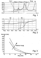
- the fully extended curve TE the Fig. 1 indicates a torque determined or estimated as part of the adaptation;
- the dashed curve TSK1 indicates a output by the control device, to be transmitted from the clutch 12 target clutch torque, the dashed line indicates the clutch torque TSK2 calculated on the clutch.
- crankshaft of the internal combustion engine 10 begins to rotate in accordance with the curve NV and accelerates its rotation until the time of about 79.74. where it is approximately equal to the speed NE of the electric machine.
- the speeds NV and NE continue to increase, since the internal combustion engine now emits power or torque itself.
- the electronic control device 26 (FIG. Fig. 4 ) outputs a target clutch torque TSK1 that is so high that the engine is safely towed or turned on.
- a clutch torque TSK2 is calculated, which, given currently correct torque characteristic stored in the control device, corresponds stationary to the torque TSK1.
- the first phase can be detected due to the delay times of the clutch and the speed detection no plausible speed NV of the engine.
- the internal combustion engine can automatically generate torque and contribute to its acceleration.
- the engine speed reaches, as soon as the clutch is fully closed, the speed of the electric machine and then continues to increase.
- the time change of the speed and the drag torque of the engine thus the actual real Istupplungsmoment can be accurately calculated or determined.
- This determined Istkupplungsmoment TE is compared with the desired clutch torque TSK1 or TSK2; From the comparison, the current coefficient of friction can be determined, so that the coefficient of friction can be adapted. Furthermore, in the event of a deviation between TSK and TE, the torque characteristic can be adapted. If the actual clutch torque is greater than the desired clutch torque, the torque characteristic curve must be raised accordingly or the friction coefficient stored in the control device must be increased. If the determined actual clutch torque TE is smaller than the setpoint clutch torque, the torque characteristic curve must be lowered or the control-internal friction coefficient must be reduced.
- Fig. 3 indicates the solid line of a desired clutch torque characteristic, in which for various actuation paths of an actuator of the clutch or the position of the clutch actuator 24 transmissible clutch torques are given.
- the dashed curve indicates measured torques or an actual characteristic whose respective values lie above the nominal values, so that the solid nominal characteristic must be adapted in the direction of the dashed actual characteristic (in the example shown, the actual friction coefficient is greater than the nominal friction value assumed by the system ).
- Different mathematical adaptation methods can be used for the correction or adaptation of the torque characteristic curve or the coefficient of friction used in the electronic control device. It is conceivable, for example, filter functions or an incremental change of the torque characteristic or the coefficient of friction, so that there are no sudden changes during the adaptation. For the point in time at which the torque characteristic or the coefficient of friction are adjusted - i.e. the old torque characteristic is corrected - there are also different possibilities. For example, this acquisition / correction can be carried out in a phase in which the clutch is fully closed, so that there are no unwanted coupling reactions in the acquisition, which can lead to comfort impairments or vibrations.
- the drag torque Mschlepp is important to know as precisely as possible. Since this drag torque depends, for example, on the engine speed and / or the temperature, the drag torque in the control device is advantageously stored in the form of a characteristic curve or characteristic map or otherwise by means of appropriate mathematical relationships such that the exact drag torque in the determination of the actual torque for the respective operating point the clutch is received.
- the adaptation can also take place in the third phase, in which the internal combustion engine itself develops power after starting.
- the internal combustion engine itself develops power after starting.
- the adaptation then enters the motor generated by the engine torque itself, which is taken from the engine map, for example, depending on the position of a load actuator of the engine and its speed.
- TE J * DN / dt - M mot . in which Mmot is the torque generated by internal combustion engine 10.
Landscapes
- Engineering & Computer Science (AREA)
- Chemical & Material Sciences (AREA)
- Combustion & Propulsion (AREA)
- Mechanical Engineering (AREA)
- Transportation (AREA)
- General Engineering & Computer Science (AREA)
- Physics & Mathematics (AREA)
- Fluid Mechanics (AREA)
- Automation & Control Theory (AREA)
- Hydraulic Clutches, Magnetic Clutches, Fluid Clutches, And Fluid Joints (AREA)
Description
- Die Erfindung betrifft ein Verfahren und eine Vorrichtung zur Reibwertadaption einer in einem Hybridantriebsstrang zwischen einer Elektromaschine und einem Verbrennungsmotor angeordneten, von einem Kupplungsaktor betätigten Reibungskupplung.
- In der Offenlegungsschrift
DE 198 38 853 A1 , die als nächstliegender Stand der Technik angesehen wird und die Merkmale der Präambel des unabhängigen Anspruchs 1 zeigt, wird eine Hybridantriebsvorrichtung für ein Fahrzeug offenbart, die in der Lage ist, das Ansprechen beim Wiederanlassen einer Verbrennungsmaschine während der Fahrt eines Fahrzeugs zu verbessern. Im Ergebnis kann ein Stoß in Folge einer Verzögerung vermindert werden. Die Hybridantriebsvorrichtung für ein Fahrzeug hat eine Verbrennungsmaschine, einen Elektromotor, eine Kupplung, eine Getriebeeinheit und eine Steuereinheit zur Steuerung der anderen Elemente. Die Steuereinheit hat eine Wartezustandsteuereinrichtung zur Realisierung einer konstanten Anlasskennlinie, um das Anlassansprechen beim Anlassen der Verbrennungsmaschine durch Übertragung der Kraft des Elektromotors auf die Verbrennungsmaschine und Steuern des Eingriffsdrucks der Kupplung zu verbessern, um somit die Verbrennungsmaschine in eine Anlassstartposition zu drehen. -
Fig. 4 zeigt eine Prinzipanordnung eines an sich bekannten Hybridantriebsstrangs eines Fahrzeugs. Ein Verbrennungsmotor 10 ist über eine Reibungskupplung 12 mit einer motorisch und generatorisch betreibbaren Elektromaschine 14 verbunden, die wiederum über einen beispielsweise hydraulisch arbeitenden Drehmomentwandler 16 mit einem automatischen Getriebe 18 verbunden ist, das angetriebene Räder 20 des nicht dargestellten Fahrzeugs antreibt. Die Elektromaschine 14 wirkt je nach Betriebszustand mit einem Energiespeicher 22 zusammen, der bei generatorischem Betrieb der Elektromaschine 14 aufgeladen wird und aus dem bei motorischem Betrieb der Elektromaschine 14 Energie entnommen wird. - Die Reibungskupplung 12 wird von einem Kupplungsaktor 24 betätigt, beispielsweise einem Elektromotor.
- Zur Steuerung des beispielhaft beschriebenen Antriebsstrangs dient eine elektronische Steuereinrichtung 26 mit Eingängen 28, die mit Sensoren zur Erfassung des Betriebszustandes des Antriebsstrangs verbunden sind, beispielsweise einem Fahrpedalsensor, einem Getriebewahlhebelsensor, einem Drehzahlsensor zur Erfassung der Drehzahl des Verbrennungsmotors 10, einem Lastsensor zur Erfassung der Stellung eines Laststellgliedes des Verbrennungsmotors 10, einem Sensor zur Erfassung der Drehzahl eines Fahrzeugrades usw. Ausgänge 30 der elektronischen Steuereinrichtung 26 sind mit Aktoren und weiteren Steuereinrichtungen zur Steuerung des Betriebs des Verbrennungsmotors, der Elektromaschine 14, des automatischen Getriebes 18 sowie gegebenenfalls des Wandlers 16 verbunden. Dargestellt ist lediglich die Verbindung eines Ausgangs der elektronischen Steuereinrichtung 26 mit dem Kupplungsaktor 24.
- Die elektronischen Steuereinrichtung 26 enthält einen Mikroprozessor mit zugehörigen Programm- und Datenspeichern, so dass die jeweiligen Aktoren bzw. Stellglieder abhängig von den Eingangssignalen nach vorbestimmten Programmen gesteuert werden. Der Aufbau und die Funktion des Antriebsstrangs, der in vielfältiger Weise abgeändert werden kann (beispielsweise kann der Wandler 16 entfallen) sind an sich bekannt und werden daher nicht erläutert.
- Für einen einwandfreien und komfortablen Betrieb des Antriebsstrangs ist die genaue Kenntnis einer Momentenkennlinie der Kupplung 12 erforderlich, die das jeweils übertragbare Kupplungsmoment in Abhängigkeit von der Stellung des Kupplungsbetätigungsgliedes bzw. des Kupplungsaktors 24 angibt. Eine Eigenart von Reibungskupplungen liegt darin, dass sich ihre Kennlinie abhängig vom Verschleiß der Reibbeläge und anderen Einflussgrößen ändert. Dazu ist bekannt, die in der Steuereinrichtung 26 abgelegte Momentenkennlinie von Zeit zu Zeit zu adaptieren, das heißt eine abgelegte Sollkennlinie durch Anfahren bestimmter Betriebszustände der Kupplung 12 mit vorbestimmen Istzuständen zu vergleichen und bei einer Abweichung zwischen den Istwerten und den Sollwerten die gespeicherte Momentenkennlinie zu adaptieren.
- Der Erfindung liegt die Aufgabe zugrunde, vorteilhafte Möglichkeiten zur Adaption der Momentenkennlinie bzw. zur Adaption des Reibwertes einer an einem Hybridantriebsstrang eines Fahrzeugs enthaltenen Reibungskupplung anzugeben.
- Der das Verfahren betreffende Teil der Erfindungsaufgabe wird mit den Merkmalen des Anspruchs 1 gelöst.
- Die Unteransprüche 2 bis 7 sind auf vorteilhafte Durchführungsformen des erfindungsgemäßen Verfahrens gerichtet.
- Der Anspruch 8 kennzeichnet den grundsätzlichen Aufbau einer erfindungsgemäßen Vorrichtung.
- Ein wesentliches Element der Erfindung liegt darin, dass bei einem Hybridantriebsstrang, bei dem die Brennkraftmaschine mittels einer betätigbaren Reibungskupplung mit einer E-Maschine verbindbar ist und angedreht bzw. angelassen werden kann, bei Kenntnis des Trägheitsmoments, des Schleppmoments, der Drehzahl sowie gegebenenfalls weiterer Betriebsparameter des Verbrennungsmotors das von der Kupplung übertragenen Moment genau ermittelt werden kann, so dass es mit einem Sollmoment verglichen werden kann und dieses Sollmoment bei einer Abweichung zwischen dem ermittelten Istmoment und dem Sollmoment adaptiert werden kann.
- Bei einem erfindungsgemäßen Verfahren zur Reibwertadaption einer in einem Hybridantriebsstrang zwischen einer Elektromaschine und einem Verbrennungsmotor angeordneten, von einem Kupplungsaktor betätigten Reibungskupplung wird der Reibwert mittels eines von der Reibungskupplung übertragenen Moments adaptiert, das bei einem Anlassen des Verbrennungsmotors mittels der Elektromaschine ermittelt wird.
- Bevorzugt enthält ein erfindungsgemäßes Verfahren folgende Schritte:
- Betätigen der Reibungskupplung zum Andrehen des Verbrennungsmotors entsprechend einer alten Momentenkennlinie derart, dass sie ein Sollmoment überträgt, das sicher zum Andrehen des Verbrennungsmotors ausreicht,
- Erfassen der Drehzahländerung des Verbrennungsmotors,
- Ermitteln des Istkupplungsmoments aus der Drehzahländerung, dem Massenträgheitsmoment und einem Moment des Verbrennungsmotors,
- Adaptieren der alten Momentenkennlinie derart, dass das Soll moment dem Istmoment entspricht.
- Das Istkupplungsmoment kann bei noch nicht befeuertem Verbrennungsmotor ermittelt werden.
- Ein Schleppmoment des Verbrennungsmotors wird vorteilhafterweise in Abhängigkeit von Betriebsparametern des Verbrennungsmotors berücksichtigt.
- Das Istkupplungsmoment kann bei bereits ein Moment erzeugendem Verbrennungsmotor ermittelt werden.
- Die Adaption erfolgt beispielsweise inkrementell.
- Die Adaption kann in einer Durchführungsform des erfindungsgemäßen Verfahrens erst bei voll geschlossener Reibungskupplung erfolgen.
- Eine Vorrichtung zur Reibwertadaption einer in einem Hybridantriebsstrang zwischen einer Elektromaschine und einem Verbrennungsmotor angeordneten, von einem Aktor betätigten Reibungskupplung, enthält eine elektronische Steuereinrichtung mit Eingängen, die mit Sensoren zur Erfassung von Betriebszuständen des Hybridantriebsstrangs verbunden ist und wenigstens einem mit dem Kupplungsaktor verbundenen Ausgang, welche Steuereinrichtung eine Momentenkennlinie, die ein übertragbares Kupplungsmoment in Abhängigkeit von der Stellung des Kupplungsaktors angibt, und ein Programm enthält, das die Momentenkennlinie entsprechend einem der vorhergehend genannten Verfahren adaptiert.
- Die Reibungskupplung, die im Beispiel der
Fig. 4 eine Trennkupplung ist, die nur zum Anlassen und Abschalten des Verbrennungsmotors verwendet wird, kann bei fehlendem Wandler 16 (Fig. 4 ) auch eine Anfahrkupplung sein, wenn beispielweise der Wandler fehlt und bei leerer Batterie mit dem Verbrennungsmotor angefahren werden muss. Das Getriebe kann ein automatisiertes Handschaltgetriebe sein, ein CVT-Getriebe oder ein Planetengetriebe oder ein manuell betätigtes Handschaltgetriebe sein. - Die Erfindung wird im Folgenden anhand schematischer Zeichnungen beispielsweise und mit weiteren Einzelheiten erläutert.
- Es stellen dar:
- Fig. 1 und 2
- einen Anlassvorgang mit Adaption des Reibwertes der Kupplung,
- Fig. 3
- eine Adaption einer Momentenkennlinie und
- Fig. 4
- die bereits beschriebene schematische Darstellung eines an sich bekannten Hybridantriebsstrangs.
- In den
Fig. 1 und 2 ist auf der Abszisse die Zeit in Sekunden dargestellt. Die Ordinate stellt inFig. 1 Momente, beispielsweise in Nm dar und inFig.2 Drehzahlen in 1000/min. - Die voll ausgezogenen Kurve TE der
Fig. 1 gibt ein im Rahmen der Adaption ermitteltes bzw. geschätztes Drehmoment an; die gestrichelte Kurve TSK1 gibt ein von der Steuereinrichtung ausgegebenes, von der Kupplung 12 zu übertragendes Sollkupplungsmoment an, die strichpunktierte Kurve gibt das an der Kupplung berechnete Kupplungsmoment TSK2 an. - In
Fig. 2 gibt die durchgezogenen Kurve NE die Drehzahl der Elektromaschine 14 an; die gestrichelte Kurve gibt die Drehzahl NV des Verbrennungsmotors 10 an. - Dargestellt ist ein Fall, bei dem der Verbrennungsmotor 10 durch Schließen der Kupplung 12 mittels der Elektromaschine 14 angedreht wird und am Ende der dargestellten Zeitdauer selbst Drehmoment abgibt.
- Zum Zeitpunkt etwa 79,43 wird von der Steuereinrichtung der Kupplungsaktor 24 derart angesteuert, dass die Kupplung ein Sollkupplungsmoment TSK1 übertragen soll, das deutlich über dem Moment liegt, das zum Losbrechen bzw. Andrehen der Kurbelwelle des Verbrennungsmotors 10 erforderlich ist. Das von der Steuereinrichtung entsprechend der in der Steuereinrichtung gespeicherten Momentenkennlinie sowie der Aktorposition bzw. dem Kupplungsistweg berechnete Kupplungsmoment TSK2 folgt dem Sollkupplungsmoment TSK1 mit zeitlicher Verzögerung. Die Drehzahl NE der Elektromaschine 14, die vorteilhafterweise geregelt ist, ändert sich zunächst kaum, obwohl das von der Elektromaschine 14 abgegebene Moment sich zum Zeitpunkt von etwa 79,51 zum Losbrechen der Kurbelwelle des Verbrennungsmotors 10 deutlich erhöht. Zum Zeitpunkt etwa 79,55 beginnt die Kurbelwelle des Verbrennungsmotors 10 entsprechend der Kurve NV zu drehen und beschleunigt ihre Drehung bis zum Zeitpunkt von etwa 79,74. wo sie annähernd gleich mit der Drehzahl NE der Elektromaschine wird. Die Drehzahlen NV und NE nehmen weiter zu, da der Verbrennungsmotor inzwischen selbst Leistung bzw. Drehmoment abgibt.
- Wie aus
Fig. 1 und 2 ersichtlich kann das Andrehen bzw. ein Wiederstart des Verbrennungsmotors 10 mit Hilfe der Elektromaschine 14 in drei Phasen unterteilt werden. - In der ersten Phase wird von der elektronischen Steuereinrichtung 26 (
Fig. 4 ) ein Sollkupplungsmoment TSK1 ausgegeben, das so hoch ist, dass der Verbrennungsmotor sicher angeschleppt bzw. angedreht wird. Mit den von der Steuereinrichtung erfassten Sensorengrößen wie beispielsweise einem Kupplungsistweg und der gespeicherter Momentenkennlinie wird ein Kupplungsmoment TSK2 berechnet, das bei aktuell richtiger in der Steuereinrichtung gespeicherter Momentenkennlinie stationär dem Moment TSK1 entspricht. In der ersten Phase kann bedingt durch die Verzögerungszeiten der Kupplung und die Drehzahlerfassung keine plausible Drehzahl NV des Verbrennungsmotors erkannt werden. - In der anschließenden zweiten Phase kann eine gute Zuordnung zwischen dem Istkupplungsmoment und der Drehzahländerung bzw. Beschleunigung des Verbrennungsmotors erfolgen. Der Verbrennungsmotor wird in dieser zweiten Phase geschleppt und erzeugt noch kein Moment.
- In der dritten Phase, in der das Sollkupplungsmoment TSK1 auf volles Schließen der Kupplung erhöht wird, kann der Verbrennungsmotor selbsttätig Moment erzeugen und zu seiner Beschleunigung beitragen. Die Motordrehzahl erreicht, sobald die Kupplung ganz geschlossen ist, die Drehzahl der Elektromaschine und steigt dann weiter an.
- Gemäß einer ersten Durchführungsform der Erfindung wird vorgeschlagen, in der zweiten Phase eine Reibwertadaption bzw. Momentenkennlinienadaption durchzuführen, indem die Momentenbilanz zwischen dem antreibenden Istkupplungsmoment und dem von dem Verbrennungsmotor her wirkenden Moment ausgewertet wird. Es gilt:

- Mschlepp:
- Schleppmoment (Reibungsmoment) zum Drehen der Brennkraftmaschine,
- J:
- Massenträgheitsmoment des Verbrennungsmotors,
- dNV/dt:
- zeitliche Änderung der Drehzahl der Kurbelwelle des Verbrennungsmotors.
- Aus dem Massenträgheitsmoment, der zeitlichen Änderung der Drehzahl und dem Schleppmoment des Verbrennungsmotors kann somit das aktuelle reale Istupplungsmoment genau berechnet bzw. ermittelt werden. Dieses ermittelte Istkupplungsmoment TE wird mit dem Sollkupplungsmoment TSK1 bzw. TSK2 verglichen; aus dem Vergleich kann der aktuelle Reibwert ermittelt werden, so dass der Reibwert adaptiert werden kann. Weiter kann bei einer Abweichung zwischen TSK und TE die Momentenkennlinie adaptiert werden. Ist das Istkupplungsmoment größer als das Sollkupplungsmoment, muss die Momentenkennlinie entsprechend angehoben werden bzw. der in der Steuereinrichtung abgelegte Reibwert muss erhöht werden. Ist das ermittelte Istkupplungsmoment TE kleiner als das Sollkupplungsmoment, muss die Momentenkennlinie abgesenkt werden bzw. der steuerungsintere Reibwert muss vermindert werden.
- In
Fig. 3 gibt die durchgezogene Linie einer Sollkupplungsmomentenkennlinie an, in der für verschiedene Betätigungswege eines Betätigungsgliedes der Kupplung bzw. der Stellung des Kupplungsaktors 24 übertragbare Kupplungsmomente angegeben sind. Die gestrichelte Kurve gibt gemessene Momente bzw. eine Istkennlinie an, deren jeweilige Werte über den Sollwerten liegen, so dass die durchgezogene Sollkennline in Richtung auf die gestrichelte Istkennlinie adaptiert werden muss (im dargestellten Beispiel ist der tatsächlich vorhandene Reibwert größer als der vom System angenommene Sollreibwert). - Für die die Korrektur bzw. Adaption der in der elektronischen Steuereinrichtung verwendeten Momentenkennlinie bzw. des Reibwertes können unterschiedliche mathematische Anpassungsverfahren eingesetzt werden. Denkbar sind beispielsweise Filterfunktionen oder ein inkrementelles Verändern der Momentenkennlinie bzw. des Reibwertes, so dass es während der Adaption zu keinen sprunghaften Veränderungen kommt. Für den Zeitpunkt, an dem die Momentenkennlinie bzw. der Reibwert angepasst werden - d.h. die alte Momentenkennlinie korrigiert wird -, sind ebenfalls unterschiedliche Möglichkeiten vorhanden. Beispielsweise kann diese Übernahme/ Korrektur in einer Phase durchgeführt werden, in der die Kupplung vollständig geschlossen ist, so dass es bei der Übernahme zu keinen ungewollten Kupplungsreaktionen kommt, die zu Komfortbeeinträchtigungen oder Schwingungen führen können. Bei großen Abweichungen zwischen Sollwerten und Istwerten kann noch während der Kupplungsschlupfphase die Übernahme erfolgen, wobei je nach Adaptionsverfahren darauf geachtet werden muss, dass es zu keinen sprungartigen Änderungen kommt. Es bieten sich entsprechende Rampen-/Begrenzungsfunktionen für die Adaption der Momentenkennlinie bzw. den intern abgelegten Reibwert an.
- Für die Adaption ist es wichtig, das Motorschleppmoment Mschlepp möglichst genau zu kennen. Da dieses Schleppmoment beispielsweise von der Motordrehzahl und/oder der Temperatur abhängt, ist das Schleppmoment in der Steuereinrichtung vorteilhafterweise in Form einer Kennlinie oder eines Kennfeldes oder sonstwie mittels entsprechender mathematischer Beziehungen derart abgelegt, dass für den jeweiligen Betriebspunkt das genaue Schleppmoment in die Ermittlung des Istmoments der Kupplung eingeht.
- Bei einer abgeänderten Durchführungsform des erfindungsgemäßen Verfahrens kann auch in der dritten Phase, in der der Verbrennungsmotor nach dem Anlassen selbst Leistung entfaltet, die Adaption erfolgen. In der obigen Gleichung zur Ermittlung des lstkupplungsmoments geht dann das vom Motor selbst erzeugte Motormoment ein, das aus dem Motorkennfeld beispielsweise abhängig von der Stellung eines Laststellgliedes des Verbrennungsmotors und dessen Drehzahl entnommen wird. Für die Gleichung gilt dann:

Mmot das von Verbrennungsmotor 10 erzeugte Drehmoment ist. - Für die Durchführung der Adaption gilt das vorstehend betreffend die erstgenannte Durchführungsform des erfindungsgemäßen Verfahrens Gesagte.
-
- 10
- Verbrennungsmotor
- 12
- Reibungskupplung
- 14
- Elektromaschine
- 16
- Wandler
- 18
- automatisches Getriebe
- 20
- Rad
- 22
- Energiespeicher
- 24
- Kupplungsaktor
- 26
- elektronische Steuereinrichtung
- 28
- Eingänge
Claims (7)
- Verfahren zur Reibwertadaption einer in einem Hybridantriebsstrang eines Fahrzeugs zwischen einer Elektromaschine (14) und einem Verbrennungsmotor (10) angeordneten, von einem Kupplungsaktor betätigten Reibungskupplung (12), bei welchem Verfahren der Reibwert der Reibungskupplung (12) mittels eines von der Reibungskupplung übertragenen Moments adaptiert wird, das bei einem Anlassen des Verbrennungsmotors mittels der Elektromaschine ermittelt wird, dadurch gekennzeichnet, dass das Verfahren folgende Schritte enthält:- Betätigen der Reibungskupplung (12) zum Andrehen des Verbrennungsmotors (10) entsprechend einer alten Momentenkennlinie der Reibunskupplung (12), welche das jeweils übertragbare Kupplungsmoment in Abhängigkeit von der Stellung des Kupplungsaktuator (24) angibt derart, dass sie ein Sollkupplungsmoment (TSK) überträgt, das sicher zum Andrehen des Verbrennungsmotors ausreicht,- Erfassen der zeitlichen Drehzahländerung (dNU/dt) der Kurbelwelle des Verbrennungsmotors (2),- Ermitteln des von der Reibungkupplung (12) übertragenen aktuellen realen Istkupplungsmoments (TE) aus der zeitlichen Drehzahländerung der Kurbelwelle des Verbrennungsmotors (10), dem Massenträg-, heitsmoment (7) des Verbrennungsmotors (10) und einem Schleppmoment (Mschlepp) des Verbrennungsmotors (10) entsprechend der Formel TE = 7 * dNV/dt, wobei NV die aktuelle Drehzahl des Verbrennungsmotors (10) und t den aktuellen Zeitpunkt darstellen,- Adaptieren der alten Momentenkennlinie mit Hilfe von Filterfunktionen oder inkrementellen Verändern derart, dass das Sollkupplungsmoment (TSK) dem Istkupplungsmoment (TE) entspricht , wobei wenn das aktuelle reale Istkupplungsmoment (TE) größer als das Sollkupplungsmoment (TSK) ist, muss der in der Steuereinrichtung abgelegte Reibwert erhöht werden und wenn das ermittelte aktuelle reale Istkupplungsmoment (TE) kleiner als das Sollkupplungsmoment (TSK) ist, muss der steuerungsinterne Reibwert vermindert werden..
- Verfahren nach Anspruch 1, wobei das Istkupplungsmoment bei noch nicht befeuertem Verbrennungsmotor ermittelt wird.
- Verfahren nach Anspruch 2, wobei ein Schleppmoment des Verbrennungsmotors (10) in Abhängigkeit von Betriebsparametern des Verbrennungsmotors berücksichtigt wird.
- Verfahren nach Anspruch 1, wobei das Istkupplungsmoment bei bereits ein Moment erzeugendem Verbrennungsmotor (10) ermittelt wird.
- Verfahren nach einem der Ansprüche 1 bis 4, wobei die Übernahme der Adaptionsergebnisse inkrementell erfolgt.
- Verfahren nach einem der Ansprüche 1 bis 4, wobei die Übernahme der Adaptionsergebnisse erst bei voll geschlossener Reibungskupplung (12) erfolgt.
- Vorrichtung zur Reibwertadaption einer in einem Hybridantriebsstrang eines Fahrzeugs zwischen einer Elektromaschine (14) und einem Verbrennungsmotor (10) angeordneten, von einem Aktor (24) betätigten Reibungskupplung (12),
enthaltend eine elektronische Steuereinrichtung (26) mit Eingängen (28), die mit Sensoren zur Erfassung von Betriebszuständen des Hybridantriebsstrangs des Fahrzeugs verbunden ist und wenigstens einem mit dem Kupplungsaktor (24) verbundenen Ausgang (26), Welche Steuereinrichtung eine Momentenkennlinie, die ein übertragbare Kupplungsmoment in Abhängigkeit von der Stellung des Kupplungsaktors angibt, und ein Programm enthält, welches die Momentenkennlinie entsprechend einem Verfahren nach einem der Ansprüche 1 bis 6 adaptiert.
Applications Claiming Priority (1)
| Application Number | Priority Date | Filing Date | Title |
|---|---|---|---|
| DE102007029208 | 2007-06-25 |
Publications (2)
| Publication Number | Publication Date |
|---|---|
| EP2008899A1 EP2008899A1 (de) | 2008-12-31 |
| EP2008899B1 true EP2008899B1 (de) | 2015-08-12 |
Family
ID=39829036
Family Applications (1)
| Application Number | Title | Priority Date | Filing Date |
|---|---|---|---|
| EP08010238.7A Not-in-force EP2008899B1 (de) | 2007-06-25 | 2008-06-05 | Verfahren und Vorrichtung zur Reibwertadaption einer in einem Hybridantriebsstrang angeordneten Reibungskupplung |
Country Status (3)
| Country | Link |
|---|---|
| US (1) | US8105205B2 (de) |
| EP (1) | EP2008899B1 (de) |
| DE (1) | DE102008027071A1 (de) |
Cited By (2)
| Publication number | Priority date | Publication date | Assignee | Title |
|---|---|---|---|---|
| DE102017217833A1 (de) | 2017-10-06 | 2019-04-11 | Zf Friedrichshafen Ag | Verfahren und Steuergerät zum Betreiben eines Kraftfahrzeugs |
| DE102011050559B4 (de) | 2011-05-23 | 2024-05-08 | Dr. Ing. H.C. F. Porsche Aktiengesellschaft | Antriebstrangvorrichtung für ein Hybridfahrzeug und Verfahren zum Betrieb der Antriebsstrangvorrichtung |
Families Citing this family (36)
| Publication number | Priority date | Publication date | Assignee | Title |
|---|---|---|---|---|
| DE102006048358A1 (de) * | 2006-10-12 | 2008-04-17 | Robert Bosch Gmbh | Verfahren für die Steuerung eines Hybridantriebs |
| US8142328B2 (en) * | 2007-07-05 | 2012-03-27 | Schaeffler Technologies AG & Co. KG | Method for controlling a starting clutch |
| DE102007062796A1 (de) | 2007-12-27 | 2009-07-02 | Robert Bosch Gmbh | Verfahren zum Betreiben einer Hybridantriebsvorrichtung |
| DE102009014007B4 (de) * | 2009-03-19 | 2019-07-18 | Continental Automotive Gmbh | Verfahren und Vorrichtung zum Steuern einer Hybridantriebsvorrichtung |
| GB2470015B (en) * | 2009-05-05 | 2016-05-18 | Gm Global Tech Operations Llc | Method and apparatus for estimating clutch friction |
| SE534111C2 (sv) * | 2009-09-14 | 2011-05-03 | Scania Cv Ab | Metod och system för styrning av en koppling |
| SE534245C2 (sv) * | 2009-09-14 | 2011-06-14 | Scania Cv Ab | Metod och system för bestämning av kontaktpunkten för en koppling vid ett fordon |
| CN102245453B (zh) * | 2010-03-01 | 2013-09-25 | 丰田自动车株式会社 | 动力传递控制装置 |
| DE102011016999A1 (de) * | 2010-04-26 | 2012-03-29 | Schaeffler Technologies Gmbh & Co. Kg | Verfahren zur Adaption eines Tastpunktes einer Kupplung in einem Triebstrang eines Kraftfahrzeuges |
| WO2012069034A1 (de) | 2010-11-25 | 2012-05-31 | Schaeffler Technologies AG & Co. KG | Verfahren zur ermittlung von kupplungsreibwerten sowie verfahren zur ermittlung von kupplungstastpunkten |
| CN103620253B (zh) * | 2011-03-14 | 2016-12-28 | 舍弗勒技术股份两合公司 | 用于控制摩擦离合器的方法 |
| EP2689980B1 (de) * | 2011-03-25 | 2019-04-24 | Aisin Seiki Kabushiki Kaisha | Getriebesteuerungsvorrichtung für ein hybridfahrzeug |
| DE102012007322A1 (de) * | 2012-04-12 | 2013-10-17 | Audi Ag | Verfahren zum Betreiben einer Hybridantriebsvorrichtung |
| DE102013103878B4 (de) * | 2013-04-17 | 2021-06-17 | Dr. Ing. H.C. F. Porsche Aktiengesellschaft | Verfahren und Steuereinrichtung zur Adaption einer Kennlinie einer zwischen einem Verbrennungsmotor und einem Elektromotor vorgesehenen Trennkupplung |
| DE102013215497A1 (de) * | 2013-08-07 | 2015-02-12 | Zf Friedrichshafen Ag | Verfahren zur Ermittlung mindestens eines bei einem automatischen Kraftfahrzeuggetriebe eingangsseitig wirksamen Schleppmoments |
| JP6260173B2 (ja) * | 2013-09-27 | 2018-01-17 | トヨタ自動車株式会社 | 車両の制御装置 |
| DE102014211669A1 (de) * | 2014-06-18 | 2015-12-24 | Schaeffler Technologies AG & Co. KG | Verfahren zur Ermittlung einer Tastpunktänderung einer Hybridtrennkupplung eines Hybridfahrzeuges |
| DE112014006821A5 (de) * | 2014-07-18 | 2017-03-30 | Schaeffler Technologies AG & Co. KG | Verfahren zur Bestimmung einer Tastpunktänderung und zur Adaption eines Reibwertes einer Hybridtrennkupplung eines Hybridfahrzeuges |
| DE102015213317A1 (de) * | 2014-08-13 | 2016-02-18 | Schaeffler Technologies AG & Co. KG | Verfahren zur Ermittlung eines Tastpunktes einer Hybridtrennkupplung eines Hybridfahrzeuges |
| DE102014219031A1 (de) | 2014-09-22 | 2016-03-24 | Schaeffler Technologies AG & Co. KG | Verfahren zur Ermittlung eines Reibwertes einer Trennkupplung eines Hybridfahrzeuges |
| DE102016203624A1 (de) * | 2015-03-10 | 2016-09-15 | Schaeffler Technologies AG & Co. KG | Verfahren zur Adaption eines Kupplungsmodells einer automatisierten Kupplung durch Anpassung eines Reibwertes der Kupplung |
| DE102015225215B4 (de) | 2015-12-15 | 2022-07-07 | Schaeffler Technologies AG & Co. KG | Verfahren zur initialen Bestimmung eines Reibwertes einer Hybridtrennkupplung eines Hybridfahrzeuges |
| DE102016203434B4 (de) * | 2016-03-02 | 2022-01-27 | Audi Ag | Verfahren zur Adaption eines Greifpunkts einer Trennkupplung für ein Fahrzeug |
| DE102016006976B4 (de) * | 2016-06-07 | 2018-05-30 | Audi Ag | Verfahren zum Betreiben einer Antriebseinrichtung sowie entsprechende Antriebseinrichtung |
| DE102016209998B3 (de) | 2016-06-07 | 2017-09-21 | Audi Ag | Fahrzeug sowie Verfahren zum Betreiben einer Kupplung als Anfahrelement |
| DE102017110689A1 (de) * | 2017-05-17 | 2018-11-22 | Schaeffler Technologies AG & Co. KG | Verfahren zum Bestimmen eines Fehlers eines Moments einer Brennkraftmaschine in einem Hybridantriebsstrang |
| EP3645325B1 (de) | 2017-06-26 | 2021-07-07 | Schaeffler Technologies AG & Co. KG | Verfahren und steuer- und regeleinrichtung zur kompensation eines kupplungsmoments einer hybridtrennkupplung unter berücksichtung der drehzahl einer elektrischen maschine |
| DE102018107979A1 (de) | 2018-02-01 | 2019-08-01 | Schaeffler Technologies AG & Co. KG | Verfahren zur Vermeidung einer zu hohen Schlupfdrehzahl in einer Reibkupplung in einem Antriebsstrang eines Fahrzeuges |
| DE102018110859B4 (de) * | 2018-05-07 | 2020-03-19 | Schaeffler Technologies AG & Co. KG | Verfahren zum Wiederstart eines Verbrennungsmotors in einem Hybridantriebsstrang |
| US10920899B2 (en) * | 2018-10-19 | 2021-02-16 | Flowserve Management Company | Electronic valve actuator with predictive self-calibrating torque controller |
| KR102766556B1 (ko) | 2018-10-30 | 2025-02-13 | 섀플러 테크놀로지스 아게 운트 코. 카게 | 전기 모터를 이용한 클러치 특성 변수 확인 방법 |
| DE102018128961A1 (de) | 2018-11-19 | 2020-05-20 | Schaeffler Technologies AG & Co. KG | Verfahren zur Ermittlung einer Kupplungskenngröße im Generatorbetrieb |
| DE102018130679A1 (de) | 2018-12-03 | 2020-06-04 | Schaeffler Technologies AG & Co. KG | Verfahren zur Bestimmung eines Tastpunktes einer Hybridtrennkupplung eines Hybridfahrzeuges |
| DE102019105604B3 (de) | 2019-03-06 | 2020-07-02 | Schaeffler Technologies AG & Co. KG | Verfahren zur aktiven Reibwertänderung einer in einem Antriebsstrang eines Fahrzeuges verbauten Hybridtrennkupplung |
| JP7545323B2 (ja) * | 2020-12-28 | 2024-09-04 | カワサキモータース株式会社 | 乗物制御プログラム及び乗物制御装置 |
| DE102022000542A1 (de) | 2022-02-14 | 2023-08-17 | Mercedes-Benz Group AG | Verfahren zur Adaption eines Übertragungsmoments einer Trennkupplung eines Hybridantriebsstrangs für ein Hybridfahrzeug |
Family Cites Families (10)
| Publication number | Priority date | Publication date | Assignee | Title |
|---|---|---|---|---|
| JP3775012B2 (ja) | 1997-08-29 | 2006-05-17 | アイシン・エィ・ダブリュ株式会社 | 車両用ハイブリッド駆動装置 |
| AU7381701A (en) * | 2000-04-03 | 2001-10-15 | Luk Lamellen Und Kupplungsbau Beteiligungs Kg | Gearbox |
| AU2001267328A1 (en) * | 2000-06-23 | 2002-01-02 | Luk Lamellen Und Kupplungsbau Beteiligungs Kg | Method and control device for controlling operating parameters of a driveline |
| DE10045757A1 (de) * | 2000-09-15 | 2002-03-28 | Bosch Gmbh Robert | Verfahren und Einrichtung zum Betrieb einer Kupplung |
| DE10201982A1 (de) * | 2001-01-24 | 2002-07-25 | Luk Lamellen & Kupplungsbau | Verfahren zum Steuern und/oder Regeln einer Automatisierten Kupplung eines Fahrzeuges |
| DE10349445A1 (de) * | 2002-10-26 | 2004-05-13 | Luk Lamellen Und Kupplungsbau Beteiligungs Kg | Verfahren, Vorrichtung und deren Verwendung zum Betrieb eines Kraftfahrzeuges |
| EP1762452A3 (de) * | 2005-09-08 | 2009-05-27 | Nissan Motor Co., Ltd. | Motorstartsteuerung und Verfahren |
| JP4462170B2 (ja) * | 2005-11-07 | 2010-05-12 | 日産自動車株式会社 | ハイブリッド車両のエンジン始動制御装置 |
| ATE418687T1 (de) * | 2006-02-16 | 2009-01-15 | Luk Lamellen & Kupplungsbau | Verfahren und vorrichtung zum nachstellen einer in einem fahrzeugantriebsstrang befindlichen, von einem aktor betätigten reibungskupplung |
| DE102006048358A1 (de) | 2006-10-12 | 2008-04-17 | Robert Bosch Gmbh | Verfahren für die Steuerung eines Hybridantriebs |
-
2008
- 2008-06-05 DE DE102008027071A patent/DE102008027071A1/de not_active Withdrawn
- 2008-06-05 EP EP08010238.7A patent/EP2008899B1/de not_active Not-in-force
- 2008-06-24 US US12/214,931 patent/US8105205B2/en not_active Expired - Fee Related
Cited By (2)
| Publication number | Priority date | Publication date | Assignee | Title |
|---|---|---|---|---|
| DE102011050559B4 (de) | 2011-05-23 | 2024-05-08 | Dr. Ing. H.C. F. Porsche Aktiengesellschaft | Antriebstrangvorrichtung für ein Hybridfahrzeug und Verfahren zum Betrieb der Antriebsstrangvorrichtung |
| DE102017217833A1 (de) | 2017-10-06 | 2019-04-11 | Zf Friedrichshafen Ag | Verfahren und Steuergerät zum Betreiben eines Kraftfahrzeugs |
Also Published As
| Publication number | Publication date |
|---|---|
| DE102008027071A1 (de) | 2009-01-02 |
| US20090011899A1 (en) | 2009-01-08 |
| EP2008899A1 (de) | 2008-12-31 |
| US8105205B2 (en) | 2012-01-31 |
Similar Documents
| Publication | Publication Date | Title |
|---|---|---|
| EP2008899B1 (de) | Verfahren und Vorrichtung zur Reibwertadaption einer in einem Hybridantriebsstrang angeordneten Reibungskupplung | |
| EP2931546B1 (de) | Verfahren zur steuerung eines antriebsstrangs eines kraftfahrzeuges | |
| DE19837816B4 (de) | Verfahren und Vorrichtung zum Steuern einer Kupplung | |
| DE10228709A1 (de) | Verfahren zum Adaptieren der Einstellung einer Kupplung in einem unkonventionellen Antriebsstrang eines Fahrzeugs | |
| EP2096014A2 (de) | Verfahren, Vorrichtung und deren Verwendung zum Betrieb eines Kraftfahrzeuges | |
| WO2013007464A1 (de) | Verfahren zur steuerung eines hybridantriebsstrangs eines kraftfahrzeugs | |
| WO2012083919A1 (de) | Verfahren zur steuerung eines schaltbaren planetengetriebes in einer riemenscheibenebene eines antriebsstrangs | |
| EP1564446B1 (de) | Verfahren und Vorrichtung zum Steuern eines Gangwechsels in einem Parallelschaltgetriebe eines Fahrzeuges | |
| EP2393699A1 (de) | Verfahren zum ankoppeln einer brennkraftmaschine eines parallel-hybrid-antriebsstranges | |
| DE102010049931A1 (de) | Verfahren zur Erhöhung des Kupplungsmoments | |
| DE102007006803B4 (de) | Verfahren und Vorrichtung zum Vermindern von Rupfschwingungen in einem Kraftfahrzeugantriebsstrang | |
| WO2013083336A1 (de) | Steuerungseinrichtung eines hybridfahrzeugs und verfahren zum betreiben desselben | |
| WO2017194047A1 (de) | Verfahren zur steuerung einer trennkupplung in einem hybridischen antriebsstrang | |
| DE112016002036B4 (de) | Verfahren zur Steuerung einer Kupplung eines Fahrzeuges nach Beendigung eines Segelbetriebes des Fahrzeuges | |
| DE102007045031A1 (de) | Verfahren und Vorrichtung zum Warnen bei drohender Überbeanspruchung eines Fahrzeugantriebsstrangs | |
| DE10138998A1 (de) | Vorrichtung und Verfahren zum Steuern eines Schaltablaufs bei einem lastschaltbaren Getriebe | |
| WO2008104148A1 (de) | Verfahren und vorrichtung zum steuern der kupplungen eines parallelschaltgetriebes bei einem gangwechsel | |
| DE102007046735B4 (de) | Verfahren zur Verhinderung einer Überlastung der Anfahrkupplung | |
| EP3423730B1 (de) | Verfahren zur adaption eines greifpunkts einer trennkupplung für ein fahrzeug | |
| DE10214813A1 (de) | Kraftfahrzeug | |
| DE102018110859B4 (de) | Verfahren zum Wiederstart eines Verbrennungsmotors in einem Hybridantriebsstrang | |
| WO2004087456A1 (de) | Verfahren und vorrichtung zur steuerung eines antriebsstrangs | |
| EP3797569B1 (de) | Landwirtschaftliche arbeitsmaschine und verfahren zum anfahren | |
| DE102004033716A1 (de) | Verfahren zum Betrieb eines eine Mehrfach-Kupplungseinrichtung und ein Lastschaltgetriebe aufweisenden Antriebsstrangs und derartiger Antriebsstrang mit entsprechender Steuereinheit | |
| EP1509710A1 (de) | Automatisiertes schaltgetriebe sowie verfahren zum betreiben einer getriebeeinrichtung |
Legal Events
| Date | Code | Title | Description |
|---|---|---|---|
| PUAI | Public reference made under article 153(3) epc to a published international application that has entered the european phase |
Free format text: ORIGINAL CODE: 0009012 |
|
| AK | Designated contracting states |
Kind code of ref document: A1 Designated state(s): AT BE BG CH CY CZ DE DK EE ES FI FR GB GR HR HU IE IS IT LI LT LU LV MC MT NL NO PL PT RO SE SI SK TR |
|
| AX | Request for extension of the european patent |
Extension state: AL BA MK RS |
|
| 17P | Request for examination filed |
Effective date: 20090630 |
|
| AKX | Designation fees paid |
Designated state(s): AT BE BG CH CY CZ DE DK EE ES FI FR GB GR HR HU IE IS IT LI LT LU LV MC MT NL NO PL PT RO SE SI SK TR |
|
| 17Q | First examination report despatched |
Effective date: 20090814 |
|
| RAP1 | Party data changed (applicant data changed or rights of an application transferred) |
Owner name: SCHAEFFLER TECHNOLOGIES AG & CO. KG |
|
| RAP1 | Party data changed (applicant data changed or rights of an application transferred) |
Owner name: SCHAEFFLER TECHNOLOGIES GMBH & CO. KG |
|
| REG | Reference to a national code |
Ref country code: DE Ref legal event code: R079 Ref document number: 502008013246 Country of ref document: DE Free format text: PREVIOUS MAIN CLASS: B60W0020000000 Ipc: B60K0006480000 |
|
| RIC1 | Information provided on ipc code assigned before grant |
Ipc: B60W 10/02 20060101ALI20141215BHEP Ipc: B60W 10/06 20060101ALI20141215BHEP Ipc: B60K 6/387 20071001ALI20141215BHEP Ipc: B60K 6/48 20071001AFI20141215BHEP Ipc: F16D 48/06 20060101ALI20141215BHEP Ipc: B60W 20/00 20060101ALI20141215BHEP Ipc: B60W 10/08 20060101ALI20141215BHEP |
|
| RAP1 | Party data changed (applicant data changed or rights of an application transferred) |
Owner name: SCHAEFFLER TECHNOLOGIES AG & CO. KG |
|
| GRAP | Despatch of communication of intention to grant a patent |
Free format text: ORIGINAL CODE: EPIDOSNIGR1 |
|
| INTG | Intention to grant announced |
Effective date: 20150316 |
|
| GRAS | Grant fee paid |
Free format text: ORIGINAL CODE: EPIDOSNIGR3 |
|
| GRAA | (expected) grant |
Free format text: ORIGINAL CODE: 0009210 |
|
| AK | Designated contracting states |
Kind code of ref document: B1 Designated state(s): AT BE BG CH CY CZ DE DK EE ES FI FR GB GR HR HU IE IS IT LI LT LU LV MC MT NL NO PL PT RO SE SI SK TR |
|
| REG | Reference to a national code |
Ref country code: GB Ref legal event code: FG4D Free format text: NOT ENGLISH |
|
| REG | Reference to a national code |
Ref country code: CH Ref legal event code: EP |
|
| REG | Reference to a national code |
Ref country code: AT Ref legal event code: REF Ref document number: 741805 Country of ref document: AT Kind code of ref document: T Effective date: 20150815 |
|
| REG | Reference to a national code |
Ref country code: IE Ref legal event code: FG4D Free format text: LANGUAGE OF EP DOCUMENT: GERMAN |
|
| REG | Reference to a national code |
Ref country code: DE Ref legal event code: R096 Ref document number: 502008013246 Country of ref document: DE |
|
| REG | Reference to a national code |
Ref country code: LT Ref legal event code: MG4D |
|
| REG | Reference to a national code |
Ref country code: NL Ref legal event code: MP Effective date: 20150812 |
|
| PG25 | Lapsed in a contracting state [announced via postgrant information from national office to epo] |
Ref country code: FI Free format text: LAPSE BECAUSE OF FAILURE TO SUBMIT A TRANSLATION OF THE DESCRIPTION OR TO PAY THE FEE WITHIN THE PRESCRIBED TIME-LIMIT Effective date: 20150812 Ref country code: LT Free format text: LAPSE BECAUSE OF FAILURE TO SUBMIT A TRANSLATION OF THE DESCRIPTION OR TO PAY THE FEE WITHIN THE PRESCRIBED TIME-LIMIT Effective date: 20150812 Ref country code: GR Free format text: LAPSE BECAUSE OF FAILURE TO SUBMIT A TRANSLATION OF THE DESCRIPTION OR TO PAY THE FEE WITHIN THE PRESCRIBED TIME-LIMIT Effective date: 20151113 Ref country code: NO Free format text: LAPSE BECAUSE OF FAILURE TO SUBMIT A TRANSLATION OF THE DESCRIPTION OR TO PAY THE FEE WITHIN THE PRESCRIBED TIME-LIMIT Effective date: 20151112 Ref country code: LV Free format text: LAPSE BECAUSE OF FAILURE TO SUBMIT A TRANSLATION OF THE DESCRIPTION OR TO PAY THE FEE WITHIN THE PRESCRIBED TIME-LIMIT Effective date: 20150812 |
|
| PG25 | Lapsed in a contracting state [announced via postgrant information from national office to epo] |
Ref country code: SE Free format text: LAPSE BECAUSE OF FAILURE TO SUBMIT A TRANSLATION OF THE DESCRIPTION OR TO PAY THE FEE WITHIN THE PRESCRIBED TIME-LIMIT Effective date: 20150812 Ref country code: PT Free format text: LAPSE BECAUSE OF FAILURE TO SUBMIT A TRANSLATION OF THE DESCRIPTION OR TO PAY THE FEE WITHIN THE PRESCRIBED TIME-LIMIT Effective date: 20151214 Ref country code: ES Free format text: LAPSE BECAUSE OF FAILURE TO SUBMIT A TRANSLATION OF THE DESCRIPTION OR TO PAY THE FEE WITHIN THE PRESCRIBED TIME-LIMIT Effective date: 20150812 Ref country code: IS Free format text: LAPSE BECAUSE OF FAILURE TO SUBMIT A TRANSLATION OF THE DESCRIPTION OR TO PAY THE FEE WITHIN THE PRESCRIBED TIME-LIMIT Effective date: 20151212 Ref country code: HR Free format text: LAPSE BECAUSE OF FAILURE TO SUBMIT A TRANSLATION OF THE DESCRIPTION OR TO PAY THE FEE WITHIN THE PRESCRIBED TIME-LIMIT Effective date: 20150812 Ref country code: PL Free format text: LAPSE BECAUSE OF FAILURE TO SUBMIT A TRANSLATION OF THE DESCRIPTION OR TO PAY THE FEE WITHIN THE PRESCRIBED TIME-LIMIT Effective date: 20150812 |
|
| PG25 | Lapsed in a contracting state [announced via postgrant information from national office to epo] |
Ref country code: NL Free format text: LAPSE BECAUSE OF FAILURE TO SUBMIT A TRANSLATION OF THE DESCRIPTION OR TO PAY THE FEE WITHIN THE PRESCRIBED TIME-LIMIT Effective date: 20150812 |
|
| PG25 | Lapsed in a contracting state [announced via postgrant information from national office to epo] |
Ref country code: CZ Free format text: LAPSE BECAUSE OF FAILURE TO SUBMIT A TRANSLATION OF THE DESCRIPTION OR TO PAY THE FEE WITHIN THE PRESCRIBED TIME-LIMIT Effective date: 20150812 Ref country code: IT Free format text: LAPSE BECAUSE OF FAILURE TO SUBMIT A TRANSLATION OF THE DESCRIPTION OR TO PAY THE FEE WITHIN THE PRESCRIBED TIME-LIMIT Effective date: 20150812 Ref country code: DK Free format text: LAPSE BECAUSE OF FAILURE TO SUBMIT A TRANSLATION OF THE DESCRIPTION OR TO PAY THE FEE WITHIN THE PRESCRIBED TIME-LIMIT Effective date: 20150812 Ref country code: SK Free format text: LAPSE BECAUSE OF FAILURE TO SUBMIT A TRANSLATION OF THE DESCRIPTION OR TO PAY THE FEE WITHIN THE PRESCRIBED TIME-LIMIT Effective date: 20150812 Ref country code: EE Free format text: LAPSE BECAUSE OF FAILURE TO SUBMIT A TRANSLATION OF THE DESCRIPTION OR TO PAY THE FEE WITHIN THE PRESCRIBED TIME-LIMIT Effective date: 20150812 |
|
| REG | Reference to a national code |
Ref country code: DE Ref legal event code: R097 Ref document number: 502008013246 Country of ref document: DE |
|
| PG25 | Lapsed in a contracting state [announced via postgrant information from national office to epo] |
Ref country code: RO Free format text: LAPSE BECAUSE OF FAILURE TO SUBMIT A TRANSLATION OF THE DESCRIPTION OR TO PAY THE FEE WITHIN THE PRESCRIBED TIME-LIMIT Effective date: 20150812 |
|
| PLBE | No opposition filed within time limit |
Free format text: ORIGINAL CODE: 0009261 |
|
| STAA | Information on the status of an ep patent application or granted ep patent |
Free format text: STATUS: NO OPPOSITION FILED WITHIN TIME LIMIT |
|
| REG | Reference to a national code |
Ref country code: FR Ref legal event code: PLFP Year of fee payment: 9 |
|
| 26N | No opposition filed |
Effective date: 20160513 |
|
| PG25 | Lapsed in a contracting state [announced via postgrant information from national office to epo] |
Ref country code: SI Free format text: LAPSE BECAUSE OF FAILURE TO SUBMIT A TRANSLATION OF THE DESCRIPTION OR TO PAY THE FEE WITHIN THE PRESCRIBED TIME-LIMIT Effective date: 20150812 |
|
| PG25 | Lapsed in a contracting state [announced via postgrant information from national office to epo] |
Ref country code: BE Free format text: LAPSE BECAUSE OF NON-PAYMENT OF DUE FEES Effective date: 20160630 |
|
| PG25 | Lapsed in a contracting state [announced via postgrant information from national office to epo] |
Ref country code: MC Free format text: LAPSE BECAUSE OF FAILURE TO SUBMIT A TRANSLATION OF THE DESCRIPTION OR TO PAY THE FEE WITHIN THE PRESCRIBED TIME-LIMIT Effective date: 20150812 |
|
| REG | Reference to a national code |
Ref country code: CH Ref legal event code: PL |
|
| GBPC | Gb: european patent ceased through non-payment of renewal fee |
Effective date: 20160605 |
|
| REG | Reference to a national code |
Ref country code: IE Ref legal event code: MM4A |
|
| PG25 | Lapsed in a contracting state [announced via postgrant information from national office to epo] |
Ref country code: LI Free format text: LAPSE BECAUSE OF NON-PAYMENT OF DUE FEES Effective date: 20160630 Ref country code: CH Free format text: LAPSE BECAUSE OF NON-PAYMENT OF DUE FEES Effective date: 20160630 |
|
| PG25 | Lapsed in a contracting state [announced via postgrant information from national office to epo] |
Ref country code: IE Free format text: LAPSE BECAUSE OF NON-PAYMENT OF DUE FEES Effective date: 20160605 Ref country code: GB Free format text: LAPSE BECAUSE OF NON-PAYMENT OF DUE FEES Effective date: 20160605 |
|
| REG | Reference to a national code |
Ref country code: FR Ref legal event code: PLFP Year of fee payment: 10 |
|
| REG | Reference to a national code |
Ref country code: AT Ref legal event code: MM01 Ref document number: 741805 Country of ref document: AT Kind code of ref document: T Effective date: 20160605 |
|
| PG25 | Lapsed in a contracting state [announced via postgrant information from national office to epo] |
Ref country code: AT Free format text: LAPSE BECAUSE OF NON-PAYMENT OF DUE FEES Effective date: 20160605 |
|
| PG25 | Lapsed in a contracting state [announced via postgrant information from national office to epo] |
Ref country code: CY Free format text: LAPSE BECAUSE OF FAILURE TO SUBMIT A TRANSLATION OF THE DESCRIPTION OR TO PAY THE FEE WITHIN THE PRESCRIBED TIME-LIMIT Effective date: 20150812 Ref country code: HU Free format text: LAPSE BECAUSE OF FAILURE TO SUBMIT A TRANSLATION OF THE DESCRIPTION OR TO PAY THE FEE WITHIN THE PRESCRIBED TIME-LIMIT; INVALID AB INITIO Effective date: 20080605 |
|
| PG25 | Lapsed in a contracting state [announced via postgrant information from national office to epo] |
Ref country code: LU Free format text: LAPSE BECAUSE OF NON-PAYMENT OF DUE FEES Effective date: 20160605 Ref country code: MT Free format text: LAPSE BECAUSE OF FAILURE TO SUBMIT A TRANSLATION OF THE DESCRIPTION OR TO PAY THE FEE WITHIN THE PRESCRIBED TIME-LIMIT Effective date: 20150812 Ref country code: TR Free format text: LAPSE BECAUSE OF FAILURE TO SUBMIT A TRANSLATION OF THE DESCRIPTION OR TO PAY THE FEE WITHIN THE PRESCRIBED TIME-LIMIT Effective date: 20150812 |
|
| REG | Reference to a national code |
Ref country code: FR Ref legal event code: PLFP Year of fee payment: 11 |
|
| PG25 | Lapsed in a contracting state [announced via postgrant information from national office to epo] |
Ref country code: BG Free format text: LAPSE BECAUSE OF FAILURE TO SUBMIT A TRANSLATION OF THE DESCRIPTION OR TO PAY THE FEE WITHIN THE PRESCRIBED TIME-LIMIT Effective date: 20150812 |
|
| PGFP | Annual fee paid to national office [announced via postgrant information from national office to epo] |
Ref country code: FR Payment date: 20180629 Year of fee payment: 11 |
|
| PGFP | Annual fee paid to national office [announced via postgrant information from national office to epo] |
Ref country code: DE Payment date: 20180831 Year of fee payment: 11 |
|
| RIC2 | Information provided on ipc code assigned after grant |
Ipc: B60K 6/387 20071001ALI20141215BHEP Ipc: F16D 48/06 20060101ALI20141215BHEP Ipc: B60W 10/08 20060101ALI20141215BHEP Ipc: B60W 20/00 20160101ALI20141215BHEP Ipc: B60W 10/02 20060101ALI20141215BHEP Ipc: B60K 6/48 20071001AFI20141215BHEP Ipc: B60W 10/06 20060101ALI20141215BHEP |
|
| REG | Reference to a national code |
Ref country code: DE Ref legal event code: R119 Ref document number: 502008013246 Country of ref document: DE |
|
| PG25 | Lapsed in a contracting state [announced via postgrant information from national office to epo] |
Ref country code: DE Free format text: LAPSE BECAUSE OF NON-PAYMENT OF DUE FEES Effective date: 20200101 |
|
| PG25 | Lapsed in a contracting state [announced via postgrant information from national office to epo] |
Ref country code: FR Free format text: LAPSE BECAUSE OF NON-PAYMENT OF DUE FEES Effective date: 20190630 |
|
| P01 | Opt-out of the competence of the unified patent court (upc) registered |
Effective date: 20230523 |