EP2008906A1 - Camion industriel et module de câble pour un camion industriel - Google Patents
Camion industriel et module de câble pour un camion industriel Download PDFInfo
- Publication number
- EP2008906A1 EP2008906A1 EP07111168A EP07111168A EP2008906A1 EP 2008906 A1 EP2008906 A1 EP 2008906A1 EP 07111168 A EP07111168 A EP 07111168A EP 07111168 A EP07111168 A EP 07111168A EP 2008906 A1 EP2008906 A1 EP 2008906A1
- Authority
- EP
- European Patent Office
- Prior art keywords
- cable
- truck
- package unit
- retainer
- truck part
- Prior art date
- Legal status (The legal status is an assumption and is not a legal conclusion. Google has not performed a legal analysis and makes no representation as to the accuracy of the status listed.)
- Granted
Links
Images




Classifications
-
- B—PERFORMING OPERATIONS; TRANSPORTING
- B62—LAND VEHICLES FOR TRAVELLING OTHERWISE THAN ON RAILS
- B62B—HAND-PROPELLED VEHICLES, e.g. HAND CARTS OR PERAMBULATORS; SLEDGES
- B62B3/00—Hand carts having more than one axis carrying transport wheels; Steering devices therefor; Equipment therefor
- B62B3/04—Hand carts having more than one axis carrying transport wheels; Steering devices therefor; Equipment therefor involving means for grappling or securing in place objects to be carried; Loading or unloading equipment
- B62B3/06—Hand carts having more than one axis carrying transport wheels; Steering devices therefor; Equipment therefor involving means for grappling or securing in place objects to be carried; Loading or unloading equipment for simply clearing the load from the ground
- B62B3/0612—Hand carts having more than one axis carrying transport wheels; Steering devices therefor; Equipment therefor involving means for grappling or securing in place objects to be carried; Loading or unloading equipment for simply clearing the load from the ground power operated
-
- B—PERFORMING OPERATIONS; TRANSPORTING
- B60—VEHICLES IN GENERAL
- B60R—VEHICLES, VEHICLE FITTINGS, OR VEHICLE PARTS, NOT OTHERWISE PROVIDED FOR
- B60R16/00—Electric or fluid circuits specially adapted for vehicles and not otherwise provided for; Arrangement of elements of electric or fluid circuits specially adapted for vehicles and not otherwise provided for
- B60R16/02—Electric or fluid circuits specially adapted for vehicles and not otherwise provided for; Arrangement of elements of electric or fluid circuits specially adapted for vehicles and not otherwise provided for electric constitutive elements
- B60R16/023—Electric or fluid circuits specially adapted for vehicles and not otherwise provided for; Arrangement of elements of electric or fluid circuits specially adapted for vehicles and not otherwise provided for electric constitutive elements for transmission of signals between vehicle parts or subsystems
- B60R16/027—Electric or fluid circuits specially adapted for vehicles and not otherwise provided for; Arrangement of elements of electric or fluid circuits specially adapted for vehicles and not otherwise provided for electric constitutive elements for transmission of signals between vehicle parts or subsystems between relatively movable parts of the vehicle, e.g. between steering wheel and column
Definitions
- the present invention generally relates to an industrial truck comprising a cable for transmitting control signals and/or power between a first truck part and a second truck part.
- the invention further relates to a cable module for an industrial truck.
- Cables transferring power or control signals in industrial trucks are often subject to wear. Especially combined cable loads, yielding e.g. simultaneous bending and torsion stress, have a damaging effect on the cables. Furthermore, the cables can be subject to load in the longitudinal direction and friction.
- EP1298024 A2 addresses the problem of cable wear in industrial trucks and suggests a solution wherein an electronic power unit is placed on top of a drive motor. Thereby, relative movement between the power unit and the motor, which are connected by the cable, is precluded.
- the aim of the present invention is to provide an industrial truck in which the cable wear is reduced.
- the present invention pertains to an industrial truck comprising a first and a second truck part, being arranged to be rotatively movable with respect to each other around an axis.
- a cable is connected between the first truck part and the second truck part.
- the cable can transmit control signals between the truck parts, or be arranged to supply power from one of the truck parts to the other. Also, the cable can transmit both control signals and power.
- the cable comprises a cable package unit.
- the cable of the cable package unit is structurally arranged such that a twisting of the cable package unit, upon rotative movement of the first truck part with respect to the second truck part, causes a bending of the cable within the cable package unit.
- the structural arrangement of the cable within the cable package unit can be either helical or spiral. Both shapes imply that rotative movement of one of the truck parts with respect to the other is transferred into a bending movement of the cable within the cable package unit.
- the present invention relates to a cable module for an industrial truck.
- the cable module is arranged between a first truck part and a second truck part, which are arranged to be rotatively movable with respect to each other around an axis.
- the cable module comprises a cable package unit and at least one cable retainer for affixing the cable of the cable package unit to the first or the second truck part.
- the cable of said cable package unit is structurally arranged such that a twisting of the cable package unit, upon rotative movement of the first truck part with respect to the second truck part, causes a bending of the cable within the cable package unit.
- cables endure bending better than twisting.
- the present structural arrangement of the cable within the cable package unit also entails the advantage that the cable deformation, upon rotative movement of the first truck part with respect to the second truck part, is distributed over a longer cable length. That is, a longer cable length than that of a straight cable.
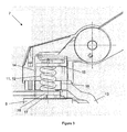
- FIG 1 shows a schematic side view of the driving and steering component 1 of an industrial truck in partial cross section.
- This component comprises a wheel 2, a transmission 3, a bearing 4, a motor 5, a brake 6 and a tiller arm mounting 7. All said elements of the driving and steering component 1 are vertically arranged in succession, wherein the wheel 2 is arranged lowest and the tiller arm mounting 7 is arranged highest.
- a tiller arm 8 extends from said tiller arm mounting, and a handle 9 is located at the end of said tiller arm.
- the tiller arm 8 is connected to the tiller arm mounting 7 by an articulated joint 10.
- a cable 11 runs from a logic unit (not shown) in the handle 9 through the tiller arm 8 and the tiller arm mounting 7 to the truck body (not shown).
- Said cable 11 transmits signals for controlling the truck from the handle 9 to a logic unit (not shown) in the truck body.
- the cable 11 comprises a cable package unit 12 which is arranged between the brake 6 and the tiller arm mounting 7.
- the cable 11 is helically arranged, i.e., the cable 11 runs in a helical manner.
- FIG. 2 A perspective view of the driving and steering component 1 of figure 1 is shown in figure 2 .
- the industrial truck is steered sideways by means of the tiller arm 8.
- Rotation of the tiller arm causes rotation of the tiller arm mounting 7, which is stationary connected to the wheel through a sweeping member 13.
- Said sweeping member has a curved cross section and is arched in its upper region so as to closely sweep around the motor 5 and transfer steering force from the tiller arm mounting 7 to the wheel 2.
- the tiller arm mounting 7, the sweeping member 13 and the wheel 2 are thus rotatively connected to the truck body about a vertical axis A ( figure 1 ), around which the cable package unit 12 is arranged.
- the structural arrangement i.e.
- the helix formation of the cable 11 within the cable package unit 12 transforms any twisting of the cable package unit 12 into a bending movement of the cable 11.
- the cable is subject to bending strain and a corresponding bending stress.
- FIGS 3 and 4 illustrate the area of the tiller arm mounting 7 in more detail.
- a cable module 14, enclosed by a dashed line in figure 3 is arranged between the tiller arm mounting 7 and the brake 6.
- the cable module 14 comprises an upper cable retainer 15 and a lower cable retainer 16, 17, between which the cable package unit 12 is contained.
- the upper cable retainer 15 comprises a cable support 18, through which the cable runs on its way to the handle 9. From the upper retainer, the cable package unit 12 extends in a direction towards the brake 6, through a vertical aperture 19 in the sweeping member 13.
- the cable 11 within the cable package unit 12 is held by the lower cable retainer, which consists of a first part 16 and a second part 17.
- FIG 5a shows a partial cross section of the tiller arm mounting 7 in perspective from below.
- the tiller arm mounting is here turned approximately 180° around axis A.
- a pin 20, protruding downwards from the tiller arm mounting 7, cooperates with a corresponding aperture (not shown) in the sweeping member 13, in order to prevent rotation of the mounting 7 with respect to the sweeping member 13.
- Figure 5b shows the upper cable retainer 15 both in perspective from below.
- the upper cable retainer 15 comprises two protruding elements 21, which, on mounting of the retainer to the tiller arm mounting, extend through a receiving aperture 22 in the tiller arm mounting in a snap fit manner, and thus fasten the upper cable retainer to the tiller arm mounting.
- the cable 11 is held between the upper cable retainer and the tiller arm mounting wall.
- a recess 23 in the latter is arranged to cooperate with a recess 24 in the upper cable retainer 15.
- said retainer 15 comprises a resilient element 25, constituting a portion of the lower part of the upper cable retainer recess 24.
- the resilient element 25 is adapted exercise a certain pressure against the cable as the cable runs through the upper cable passage, which passage is formed by the tiller arm mounting recess 23 and the upper cable retainer recess 24.
- a rotation hindering projection 26 of the upper cable retainer cooperates with a corresponding aperture 27 in the tiller arm mounting wall.
- the two parts 16, 17 that constitute the lower cable retainer are shown together with the brake 6.
- the second lower cable retainer part 17 is snap fitted to the brake by means of two opposed hook shaped brake engaging fasteners 28, one of which is shown in figure 6 .
- Said retainer part further comprises a rotation hindering projection 29 that engages a corresponding aperture 30 in the upper surface of the brake 6.
- the first lower cable retainer part 16 is snap fitted to the second retainer part 17 by means of two resilient protruding elements 31, which on assembly extend through a second retainer part aperture 32 having an inner flange. Said flange thereby acts as a locking member, fixing the protruding elements 31 axially.
- the two parts 16, 17 of the lower cable retainer retain the cable by means of opposite recesses 33, 34 and a resilient element 35.
- the two lower cable retainer parts 16, 17 are hindered from rotation with respect to one another by means of a projection at the first part 16 and a corresponding aperture 36 at the second part 17.
- the protruding elements and the corresponding apertures can switch side. Further, more than one pair of protruding element/receiving aperture can be arranged at each joint where rotation is to be prevented. Also, projections and apertures of alternative shapes can be put to use, for instance, the engaging surfaces of the joints can be serrated.
- the upper and lower cable retainers 15, 16, 17 firmly secure the upper and lower ends of the cable package unit 12 respectively.
- the inner surfaces 24, 33, 34 of the cable retainers, and the recess 23 of the tiller arm mounting 7, all of which face the cable, have semicircular cross sections, are smooth and correspond well to the form of the cable 11.
- the cable engaging surfaces of the recesses and the resilient elements 25, 35 form upper and lower passages of essentially circular cross section for the cable 11.
- both the upper and the lower cable retainer can be of two-part form (present lower retainer 16, 17) or of one part form (present upper retainer 15).
- the motor 5 does not rotate as the truck is controlled by means of the tiller arm 8.
- the motor being stationary with respect to the truck body, can thus be supplied with power from a battery in the truck via stationary power cables, which are not subject to substantive mechanical cable wear.
- the function of the cable 11, connecting the handle 9 and the truck body is to transmit control signals.
- the motor is not stationary. Instead, the motor rotates with the tiller arm.
- a present cable package unit 12 of the present type can be put to use for transmitting power to the motor.
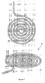
- An alternative structural arrangement of the cable within the cable package unit is a spiral formation, see figure 7 .
- the helically formed cable of the cable package unit in figure 3 has a height which is roughly equivalent to the number of cable turns times the cable thickness, plus the height of all interstices between the turns.
- the height of a spirally shaped cable 37 is, however, equal to the cable thickness.
- Said spiral can be an Archimedean spiral, having evenly spaced turns ( figure 7 ), or a logarithmic spiral (not shown), in which the spacings between adjacent turns increase in geometric progression.
- An Archimedean spiral entails the advantage of minimizing the outer diametrical size of the spiral, whereas a logarithmic spiral ensures sufficient spacing and thus reduced risk of frictional contact between successive turns.
Landscapes
- Engineering & Computer Science (AREA)
- Mechanical Engineering (AREA)
- Chemical & Material Sciences (AREA)
- Combustion & Propulsion (AREA)
- Transportation (AREA)
- Flexible Shafts (AREA)
- Soil Working Implements (AREA)
- Agricultural Machines (AREA)
Priority Applications (1)
| Application Number | Priority Date | Filing Date | Title |
|---|---|---|---|
| EP20070111168 EP2008906B1 (fr) | 2007-06-27 | 2007-06-27 | Camion industriel et module de câble pour un camion industriel |
Applications Claiming Priority (1)
| Application Number | Priority Date | Filing Date | Title |
|---|---|---|---|
| EP20070111168 EP2008906B1 (fr) | 2007-06-27 | 2007-06-27 | Camion industriel et module de câble pour un camion industriel |
Publications (2)
| Publication Number | Publication Date |
|---|---|
| EP2008906A1 true EP2008906A1 (fr) | 2008-12-31 |
| EP2008906B1 EP2008906B1 (fr) | 2013-03-13 |
Family
ID=38676046
Family Applications (1)
| Application Number | Title | Priority Date | Filing Date |
|---|---|---|---|
| EP20070111168 Active EP2008906B1 (fr) | 2007-06-27 | 2007-06-27 | Camion industriel et module de câble pour un camion industriel |
Country Status (1)
| Country | Link |
|---|---|
| EP (1) | EP2008906B1 (fr) |
Cited By (1)
| Publication number | Priority date | Publication date | Assignee | Title |
|---|---|---|---|---|
| CN114589729A (zh) * | 2022-02-24 | 2022-06-07 | 埃夫特智能装备股份有限公司 | 一种工业机器人的电缆走线结构 |
Citations (5)
| Publication number | Priority date | Publication date | Assignee | Title |
|---|---|---|---|---|
| US2325396A (en) * | 1941-12-26 | 1943-07-27 | Shepard Co Lewis | Truck having booster mechanism |
| US2592091A (en) | 1948-08-11 | 1952-04-08 | Towmotor Corp | Motorized hand truck |
| US6260646B1 (en) * | 1999-04-29 | 2001-07-17 | Raul U. Fernandez | Power-assisted pallet truck |
| EP1298024A2 (fr) | 2001-10-01 | 2003-04-02 | Still S.A.R.L. | Platine électrique tournante |
| US20050164524A1 (en) * | 2002-08-05 | 2005-07-28 | Leopold Kostal Gmbh & Co. Kg | Connecting device |
-
2007
- 2007-06-27 EP EP20070111168 patent/EP2008906B1/fr active Active
Patent Citations (5)
| Publication number | Priority date | Publication date | Assignee | Title |
|---|---|---|---|---|
| US2325396A (en) * | 1941-12-26 | 1943-07-27 | Shepard Co Lewis | Truck having booster mechanism |
| US2592091A (en) | 1948-08-11 | 1952-04-08 | Towmotor Corp | Motorized hand truck |
| US6260646B1 (en) * | 1999-04-29 | 2001-07-17 | Raul U. Fernandez | Power-assisted pallet truck |
| EP1298024A2 (fr) | 2001-10-01 | 2003-04-02 | Still S.A.R.L. | Platine électrique tournante |
| US20050164524A1 (en) * | 2002-08-05 | 2005-07-28 | Leopold Kostal Gmbh & Co. Kg | Connecting device |
Cited By (1)
| Publication number | Priority date | Publication date | Assignee | Title |
|---|---|---|---|---|
| CN114589729A (zh) * | 2022-02-24 | 2022-06-07 | 埃夫特智能装备股份有限公司 | 一种工业机器人的电缆走线结构 |
Also Published As
| Publication number | Publication date |
|---|---|
| EP2008906B1 (fr) | 2013-03-13 |
Similar Documents
| Publication | Publication Date | Title |
|---|---|---|
| TWI520719B (zh) | 握持裝置 | |
| US6354395B1 (en) | Delashed worm gear assembly and electric power assist apparatus | |
| US7213677B2 (en) | Motor-driven type power steering apparatus | |
| EP1734285A2 (fr) | Vis à billes | |
| EP1764285B1 (fr) | Dispositif d'assistance électrique de direction de véhicule automobile | |
| EP2708443A1 (fr) | Unité de boîtier de direction à crémaillère | |
| EP2484936A1 (fr) | Actionneur linéaire | |
| CN107771145A (zh) | 滚珠丝杆传动装置和机动车的配备有该滚珠丝杆传动装置的转向装置 | |
| CN102216115B (zh) | 用于支承线性驱动装置的装置 | |
| CN109963770B (zh) | 转向传动机构和转向系统 | |
| KR20160133968A (ko) | 전동식 동력 보조 조향장치의 감속기 | |
| EP1790868B1 (fr) | Arbre extensible | |
| CN104684789A (zh) | 滚珠丝杠传动机构以及具有该传动机构的动力转向系统 | |
| JP2004521818A (ja) | 低摩擦ローラヨークの設計のラック及びピニオンステアリング歯車 | |
| EP2008906B1 (fr) | Camion industriel et module de câble pour un camion industriel | |
| US6490942B1 (en) | Spindle drive having encased spindle nut with break-free moment reducing opposite end collars | |
| KR20110076112A (ko) | 전동식 동력 보조 조향장치의 감속기 및 이를 이용한 전동식 동력 보조 조향장치 | |
| US20120186371A1 (en) | Rack and Pinion Steering Device | |
| US20180015943A1 (en) | Device for introducing an auxiliary torque into a steering shaft | |
| KR20110096816A (ko) | 전동식 동력 보조 조향장치의 감속기 및 이를 구비한 전동식 동력 보조 조향장치 | |
| JP2014184769A (ja) | ステアリング装置 | |
| CN115103965B (zh) | 轴承组件 | |
| EP2128470B1 (fr) | Ensemble de couplage de rotor et d'anneau | |
| MX2012014960A (es) | Estabilizador de longitud variable para vehiculo, y vehiculo con el estabilizador de longitud variable. | |
| KR100647116B1 (ko) | 차량의 스티어링 장치 |
Legal Events
| Date | Code | Title | Description |
|---|---|---|---|
| PUAI | Public reference made under article 153(3) epc to a published international application that has entered the european phase |
Free format text: ORIGINAL CODE: 0009012 |
|
| AK | Designated contracting states |
Kind code of ref document: A1 Designated state(s): AT BE BG CH CY CZ DE DK EE ES FI FR GB GR HU IE IS IT LI LT LU LV MC MT NL PL PT RO SE SI SK TR |
|
| AX | Request for extension of the european patent |
Extension state: AL BA HR MK RS |
|
| 17P | Request for examination filed |
Effective date: 20090602 |
|
| 17Q | First examination report despatched |
Effective date: 20090625 |
|
| AKX | Designation fees paid |
Designated state(s): AT BE BG CH CY CZ DE DK EE ES FI FR GB GR HU IE IS IT LI LT LU LV MC MT NL PL PT RO SE SI SK TR |
|
| GRAP | Despatch of communication of intention to grant a patent |
Free format text: ORIGINAL CODE: EPIDOSNIGR1 |
|
| GRAS | Grant fee paid |
Free format text: ORIGINAL CODE: EPIDOSNIGR3 |
|
| GRAA | (expected) grant |
Free format text: ORIGINAL CODE: 0009210 |
|
| AK | Designated contracting states |
Kind code of ref document: B1 Designated state(s): AT BE BG CH CY CZ DE DK EE ES FI FR GB GR HU IE IS IT LI LT LU LV MC MT NL PL PT RO SE SI SK TR |
|
| REG | Reference to a national code |
Ref country code: GB Ref legal event code: FG4D |
|
| REG | Reference to a national code |
Ref country code: CH Ref legal event code: EP Ref country code: AT Ref legal event code: REF Ref document number: 600618 Country of ref document: AT Kind code of ref document: T Effective date: 20130315 |
|
| REG | Reference to a national code |
Ref country code: IE Ref legal event code: FG4D |
|
| REG | Reference to a national code |
Ref country code: DE Ref legal event code: R096 Ref document number: 602007028992 Country of ref document: DE Effective date: 20130508 |
|
| REG | Reference to a national code |
Ref country code: SE Ref legal event code: TRGR |
|
| PG25 | Lapsed in a contracting state [announced via postgrant information from national office to epo] |
Ref country code: LT Free format text: LAPSE BECAUSE OF FAILURE TO SUBMIT A TRANSLATION OF THE DESCRIPTION OR TO PAY THE FEE WITHIN THE PRESCRIBED TIME-LIMIT Effective date: 20130313 Ref country code: ES Free format text: LAPSE BECAUSE OF FAILURE TO SUBMIT A TRANSLATION OF THE DESCRIPTION OR TO PAY THE FEE WITHIN THE PRESCRIBED TIME-LIMIT Effective date: 20130624 Ref country code: BG Free format text: LAPSE BECAUSE OF FAILURE TO SUBMIT A TRANSLATION OF THE DESCRIPTION OR TO PAY THE FEE WITHIN THE PRESCRIBED TIME-LIMIT Effective date: 20130613 |
|
| REG | Reference to a national code |
Ref country code: AT Ref legal event code: MK05 Ref document number: 600618 Country of ref document: AT Kind code of ref document: T Effective date: 20130313 |
|
| REG | Reference to a national code |
Ref country code: NL Ref legal event code: VDEP Effective date: 20130313 |
|
| REG | Reference to a national code |
Ref country code: LT Ref legal event code: MG4D |
|
| PG25 | Lapsed in a contracting state [announced via postgrant information from national office to epo] |
Ref country code: GR Free format text: LAPSE BECAUSE OF FAILURE TO SUBMIT A TRANSLATION OF THE DESCRIPTION OR TO PAY THE FEE WITHIN THE PRESCRIBED TIME-LIMIT Effective date: 20130614 Ref country code: SI Free format text: LAPSE BECAUSE OF FAILURE TO SUBMIT A TRANSLATION OF THE DESCRIPTION OR TO PAY THE FEE WITHIN THE PRESCRIBED TIME-LIMIT Effective date: 20130313 Ref country code: FI Free format text: LAPSE BECAUSE OF FAILURE TO SUBMIT A TRANSLATION OF THE DESCRIPTION OR TO PAY THE FEE WITHIN THE PRESCRIBED TIME-LIMIT Effective date: 20130313 Ref country code: LV Free format text: LAPSE BECAUSE OF FAILURE TO SUBMIT A TRANSLATION OF THE DESCRIPTION OR TO PAY THE FEE WITHIN THE PRESCRIBED TIME-LIMIT Effective date: 20130313 |
|
| PG25 | Lapsed in a contracting state [announced via postgrant information from national office to epo] |
Ref country code: BE Free format text: LAPSE BECAUSE OF FAILURE TO SUBMIT A TRANSLATION OF THE DESCRIPTION OR TO PAY THE FEE WITHIN THE PRESCRIBED TIME-LIMIT Effective date: 20130313 |
|
| PG25 | Lapsed in a contracting state [announced via postgrant information from national office to epo] |
Ref country code: NL Free format text: LAPSE BECAUSE OF FAILURE TO SUBMIT A TRANSLATION OF THE DESCRIPTION OR TO PAY THE FEE WITHIN THE PRESCRIBED TIME-LIMIT Effective date: 20130313 Ref country code: AT Free format text: LAPSE BECAUSE OF FAILURE TO SUBMIT A TRANSLATION OF THE DESCRIPTION OR TO PAY THE FEE WITHIN THE PRESCRIBED TIME-LIMIT Effective date: 20130313 Ref country code: EE Free format text: LAPSE BECAUSE OF FAILURE TO SUBMIT A TRANSLATION OF THE DESCRIPTION OR TO PAY THE FEE WITHIN THE PRESCRIBED TIME-LIMIT Effective date: 20130313 Ref country code: IS Free format text: LAPSE BECAUSE OF FAILURE TO SUBMIT A TRANSLATION OF THE DESCRIPTION OR TO PAY THE FEE WITHIN THE PRESCRIBED TIME-LIMIT Effective date: 20130713 Ref country code: RO Free format text: LAPSE BECAUSE OF FAILURE TO SUBMIT A TRANSLATION OF THE DESCRIPTION OR TO PAY THE FEE WITHIN THE PRESCRIBED TIME-LIMIT Effective date: 20130313 Ref country code: PT Free format text: LAPSE BECAUSE OF FAILURE TO SUBMIT A TRANSLATION OF THE DESCRIPTION OR TO PAY THE FEE WITHIN THE PRESCRIBED TIME-LIMIT Effective date: 20130715 Ref country code: SK Free format text: LAPSE BECAUSE OF FAILURE TO SUBMIT A TRANSLATION OF THE DESCRIPTION OR TO PAY THE FEE WITHIN THE PRESCRIBED TIME-LIMIT Effective date: 20130313 Ref country code: CZ Free format text: LAPSE BECAUSE OF FAILURE TO SUBMIT A TRANSLATION OF THE DESCRIPTION OR TO PAY THE FEE WITHIN THE PRESCRIBED TIME-LIMIT Effective date: 20130313 |
|
| PG25 | Lapsed in a contracting state [announced via postgrant information from national office to epo] |
Ref country code: PL Free format text: LAPSE BECAUSE OF FAILURE TO SUBMIT A TRANSLATION OF THE DESCRIPTION OR TO PAY THE FEE WITHIN THE PRESCRIBED TIME-LIMIT Effective date: 20130313 Ref country code: CY Free format text: LAPSE BECAUSE OF FAILURE TO SUBMIT A TRANSLATION OF THE DESCRIPTION OR TO PAY THE FEE WITHIN THE PRESCRIBED TIME-LIMIT Effective date: 20130313 |
|
| PLBE | No opposition filed within time limit |
Free format text: ORIGINAL CODE: 0009261 |
|
| STAA | Information on the status of an ep patent application or granted ep patent |
Free format text: STATUS: NO OPPOSITION FILED WITHIN TIME LIMIT |
|
| PG25 | Lapsed in a contracting state [announced via postgrant information from national office to epo] |
Ref country code: DK Free format text: LAPSE BECAUSE OF FAILURE TO SUBMIT A TRANSLATION OF THE DESCRIPTION OR TO PAY THE FEE WITHIN THE PRESCRIBED TIME-LIMIT Effective date: 20130313 Ref country code: MC Free format text: LAPSE BECAUSE OF FAILURE TO SUBMIT A TRANSLATION OF THE DESCRIPTION OR TO PAY THE FEE WITHIN THE PRESCRIBED TIME-LIMIT Effective date: 20130313 |
|
| REG | Reference to a national code |
Ref country code: CH Ref legal event code: PL |
|
| 26N | No opposition filed |
Effective date: 20131216 |
|
| REG | Reference to a national code |
Ref country code: IE Ref legal event code: MM4A |
|
| REG | Reference to a national code |
Ref country code: DE Ref legal event code: R097 Ref document number: 602007028992 Country of ref document: DE Effective date: 20131216 |
|
| PG25 | Lapsed in a contracting state [announced via postgrant information from national office to epo] |
Ref country code: LI Free format text: LAPSE BECAUSE OF NON-PAYMENT OF DUE FEES Effective date: 20130630 Ref country code: IE Free format text: LAPSE BECAUSE OF NON-PAYMENT OF DUE FEES Effective date: 20130627 Ref country code: CH Free format text: LAPSE BECAUSE OF NON-PAYMENT OF DUE FEES Effective date: 20130630 |
|
| PG25 | Lapsed in a contracting state [announced via postgrant information from national office to epo] |
Ref country code: MT Free format text: LAPSE BECAUSE OF FAILURE TO SUBMIT A TRANSLATION OF THE DESCRIPTION OR TO PAY THE FEE WITHIN THE PRESCRIBED TIME-LIMIT Effective date: 20130313 |
|
| PG25 | Lapsed in a contracting state [announced via postgrant information from national office to epo] |
Ref country code: TR Free format text: LAPSE BECAUSE OF FAILURE TO SUBMIT A TRANSLATION OF THE DESCRIPTION OR TO PAY THE FEE WITHIN THE PRESCRIBED TIME-LIMIT Effective date: 20130313 |
|
| PG25 | Lapsed in a contracting state [announced via postgrant information from national office to epo] |
Ref country code: HU Free format text: LAPSE BECAUSE OF FAILURE TO SUBMIT A TRANSLATION OF THE DESCRIPTION OR TO PAY THE FEE WITHIN THE PRESCRIBED TIME-LIMIT; INVALID AB INITIO Effective date: 20070627 Ref country code: LU Free format text: LAPSE BECAUSE OF NON-PAYMENT OF DUE FEES Effective date: 20130627 |
|
| REG | Reference to a national code |
Ref country code: FR Ref legal event code: PLFP Year of fee payment: 10 |
|
| PGFP | Annual fee paid to national office [announced via postgrant information from national office to epo] |
Ref country code: IT Payment date: 20160621 Year of fee payment: 10 |
|
| REG | Reference to a national code |
Ref country code: FR Ref legal event code: PLFP Year of fee payment: 11 |
|
| PG25 | Lapsed in a contracting state [announced via postgrant information from national office to epo] |
Ref country code: IT Free format text: LAPSE BECAUSE OF NON-PAYMENT OF DUE FEES Effective date: 20170627 |
|
| REG | Reference to a national code |
Ref country code: FR Ref legal event code: PLFP Year of fee payment: 12 |
|
| P01 | Opt-out of the competence of the unified patent court (upc) registered |
Effective date: 20230526 |
|
| PGFP | Annual fee paid to national office [announced via postgrant information from national office to epo] |
Ref country code: DE Payment date: 20250626 Year of fee payment: 19 |
|
| PGFP | Annual fee paid to national office [announced via postgrant information from national office to epo] |
Ref country code: GB Payment date: 20250617 Year of fee payment: 19 |
|
| PGFP | Annual fee paid to national office [announced via postgrant information from national office to epo] |
Ref country code: FR Payment date: 20250624 Year of fee payment: 19 |
|
| PGFP | Annual fee paid to national office [announced via postgrant information from national office to epo] |
Ref country code: SE Payment date: 20250619 Year of fee payment: 19 |