EP2008965A2 - Resonanzvorrichtung mit piezoelektrischer Erfassung für den Einsatz in Oberflächentechnologien - Google Patents
Resonanzvorrichtung mit piezoelektrischer Erfassung für den Einsatz in Oberflächentechnologien Download PDFInfo
- Publication number
- EP2008965A2 EP2008965A2 EP08158743A EP08158743A EP2008965A2 EP 2008965 A2 EP2008965 A2 EP 2008965A2 EP 08158743 A EP08158743 A EP 08158743A EP 08158743 A EP08158743 A EP 08158743A EP 2008965 A2 EP2008965 A2 EP 2008965A2
- Authority
- EP
- European Patent Office
- Prior art keywords
- resonator
- piezoresistive
- strain gauge
- gauge
- silicon
- Prior art date
- Legal status (The legal status is an assumption and is not a legal conclusion. Google has not performed a legal analysis and makes no representation as to the accuracy of the status listed.)
- Granted
Links
Images


Classifications
-
- B—PERFORMING OPERATIONS; TRANSPORTING
- B81—MICROSTRUCTURAL TECHNOLOGY
- B81B—MICROSTRUCTURAL DEVICES OR SYSTEMS, e.g. MICROMECHANICAL DEVICES
- B81B3/00—Devices comprising flexible or deformable elements, e.g. comprising elastic tongues or membranes
- B81B3/0064—Constitution or structural means for improving or controlling the physical properties of a device
- B81B3/0086—Electrical characteristics, e.g. reducing driving voltage, improving resistance to peak voltage
-
- G—PHYSICS
- G01—MEASURING; TESTING
- G01C—MEASURING DISTANCES, LEVELS OR BEARINGS; SURVEYING; NAVIGATION; GYROSCOPIC INSTRUMENTS; PHOTOGRAMMETRY OR VIDEOGRAMMETRY
- G01C19/00—Gyroscopes; Turn-sensitive devices using vibrating masses; Turn-sensitive devices without moving masses; Measuring angular rate using gyroscopic effects
- G01C19/56—Turn-sensitive devices using vibrating masses, e.g. vibratory angular rate sensors based on Coriolis forces
- G01C19/5719—Turn-sensitive devices using vibrating masses, e.g. vibratory angular rate sensors based on Coriolis forces using planar vibrating masses driven in a translation vibration along an axis
- G01C19/5733—Structural details or topology
- G01C19/574—Structural details or topology the devices having two sensing masses in anti-phase motion
-
- G—PHYSICS
- G01—MEASURING; TESTING
- G01C—MEASURING DISTANCES, LEVELS OR BEARINGS; SURVEYING; NAVIGATION; GYROSCOPIC INSTRUMENTS; PHOTOGRAMMETRY OR VIDEOGRAMMETRY
- G01C19/00—Gyroscopes; Turn-sensitive devices using vibrating masses; Turn-sensitive devices without moving masses; Measuring angular rate using gyroscopic effects
- G01C19/56—Turn-sensitive devices using vibrating masses, e.g. vibratory angular rate sensors based on Coriolis forces
- G01C19/5719—Turn-sensitive devices using vibrating masses, e.g. vibratory angular rate sensors based on Coriolis forces using planar vibrating masses driven in a translation vibration along an axis
- G01C19/5733—Structural details or topology
- G01C19/5755—Structural details or topology the devices having a single sensing mass
-
- G—PHYSICS
- G01—MEASURING; TESTING
- G01C—MEASURING DISTANCES, LEVELS OR BEARINGS; SURVEYING; NAVIGATION; GYROSCOPIC INSTRUMENTS; PHOTOGRAMMETRY OR VIDEOGRAMMETRY
- G01C19/00—Gyroscopes; Turn-sensitive devices using vibrating masses; Turn-sensitive devices without moving masses; Measuring angular rate using gyroscopic effects
- G01C19/56—Turn-sensitive devices using vibrating masses, e.g. vibratory angular rate sensors based on Coriolis forces
- G01C19/5719—Turn-sensitive devices using vibrating masses, e.g. vibratory angular rate sensors based on Coriolis forces using planar vibrating masses driven in a translation vibration along an axis
- G01C19/5769—Manufacturing; Mounting; Housings
-
- G—PHYSICS
- G01—MEASURING; TESTING
- G01L—MEASURING FORCE, STRESS, TORQUE, WORK, MECHANICAL POWER, MECHANICAL EFFICIENCY, OR FLUID PRESSURE
- G01L1/00—Measuring force or stress, in general
- G01L1/18—Measuring force or stress, in general using properties of piezo-resistive materials, i.e. materials of which the ohmic resistance varies according to changes in magnitude or direction of force applied to the material
- G01L1/183—Measuring force or stress, in general using properties of piezo-resistive materials, i.e. materials of which the ohmic resistance varies according to changes in magnitude or direction of force applied to the material by measuring variations of frequency of vibrating piezo-resistive material
-
- G—PHYSICS
- G01—MEASURING; TESTING
- G01P—MEASURING LINEAR OR ANGULAR SPEED, ACCELERATION, DECELERATION, OR SHOCK; INDICATING PRESENCE, ABSENCE, OR DIRECTION, OF MOVEMENT
- G01P15/00—Measuring acceleration; Measuring deceleration; Measuring shock, i.e. sudden change of acceleration
- G01P15/02—Measuring acceleration; Measuring deceleration; Measuring shock, i.e. sudden change of acceleration by making use of inertia forces using solid seismic masses
- G01P15/08—Measuring acceleration; Measuring deceleration; Measuring shock, i.e. sudden change of acceleration by making use of inertia forces using solid seismic masses with conversion into electric or magnetic values
- G01P15/0802—Details
-
- G—PHYSICS
- G01—MEASURING; TESTING
- G01P—MEASURING LINEAR OR ANGULAR SPEED, ACCELERATION, DECELERATION, OR SHOCK; INDICATING PRESENCE, ABSENCE, OR DIRECTION, OF MOVEMENT
- G01P15/00—Measuring acceleration; Measuring deceleration; Measuring shock, i.e. sudden change of acceleration
- G01P15/02—Measuring acceleration; Measuring deceleration; Measuring shock, i.e. sudden change of acceleration by making use of inertia forces using solid seismic masses
- G01P15/08—Measuring acceleration; Measuring deceleration; Measuring shock, i.e. sudden change of acceleration by making use of inertia forces using solid seismic masses with conversion into electric or magnetic values
- G01P15/097—Measuring acceleration; Measuring deceleration; Measuring shock, i.e. sudden change of acceleration by making use of inertia forces using solid seismic masses with conversion into electric or magnetic values by vibratory elements
-
- H—ELECTRICITY
- H03—ELECTRONIC CIRCUITRY
- H03H—IMPEDANCE NETWORKS, e.g. RESONANT CIRCUITS; RESONATORS
- H03H9/00—Networks comprising electromechanical or electro-acoustic elements; Electromechanical resonators
- H03H9/02—Details
- H03H9/02244—Details of microelectro-mechanical resonators
- H03H9/02259—Driving or detection means
-
- B—PERFORMING OPERATIONS; TRANSPORTING
- B81—MICROSTRUCTURAL TECHNOLOGY
- B81B—MICROSTRUCTURAL DEVICES OR SYSTEMS, e.g. MICROMECHANICAL DEVICES
- B81B2201/00—Specific applications of microelectromechanical systems
- B81B2201/02—Sensors
- B81B2201/0228—Inertial sensors
- B81B2201/0235—Accelerometers
-
- B—PERFORMING OPERATIONS; TRANSPORTING
- B81—MICROSTRUCTURAL TECHNOLOGY
- B81B—MICROSTRUCTURAL DEVICES OR SYSTEMS, e.g. MICROMECHANICAL DEVICES
- B81B2201/00—Specific applications of microelectromechanical systems
- B81B2201/02—Sensors
- B81B2201/0228—Inertial sensors
- B81B2201/0242—Gyroscopes
-
- B—PERFORMING OPERATIONS; TRANSPORTING
- B81—MICROSTRUCTURAL TECHNOLOGY
- B81B—MICROSTRUCTURAL DEVICES OR SYSTEMS, e.g. MICROMECHANICAL DEVICES
- B81B2201/00—Specific applications of microelectromechanical systems
- B81B2201/02—Sensors
- B81B2201/0264—Pressure sensors
-
- B—PERFORMING OPERATIONS; TRANSPORTING
- B81—MICROSTRUCTURAL TECHNOLOGY
- B81B—MICROSTRUCTURAL DEVICES OR SYSTEMS, e.g. MICROMECHANICAL DEVICES
- B81B2201/00—Specific applications of microelectromechanical systems
- B81B2201/02—Sensors
- B81B2201/0271—Resonators; ultrasonic resonators
Definitions
- the invention relates to a resonant device with piezoresistive detection made in surface technologies.
- the field of the invention is in particular that of silicon micro / nano-sensors, accelerometers, gyrometers, force sensors.
- the field of the invention is that of MEMS ("Micro Electro-Mechanical System”) sensors in surface technology, as described, for example, in the document referenced [1] at the end of the description.
- MEMS Micro Electro-Mechanical System
- the field of the invention is in particular that of resonant sensors with piezoresistive detection made in surface technology, presenting a high sensitivity and precision (Signal / noise ratio, low temperature drift), adaptable to NEMS sensors, that is to say ie, sensors of very small dimensions (nanoscale).
- the document referenced [3] describes another type of sensor in which the gauges are defined by etching silicon. Silicon is no longer doped on the surface and the detection is done in the plane. Such a configuration is well suited to surface technology and the realization of sensors of very small dimensions (NEMS). On the other hand, it does not make it possible to obtain significant sensitivities and stabilities.
- the response of the sensor is, in fact, directly proportional to the signal of the gauges piezoresistive. However, the piezoresistive coefficients are strongly dependent on the temperature.
- the object of the invention is to overcome the drawbacks of devices of the known art by proposing a resonant device (resonator and / or sensor) with piezoresistive detection, produced in surface technology, presenting a high sensitivity and precision (good signal ratio / noise, low temperature drift), simpler and more efficient for small dimensions.
- the invention relates to a resonant device for detection in the piezoresistive plane produced in surface technologies on a substrate, characterized in that it comprises a resonator connected to this substrate by at least one embedding, means for exciting this resonator and detection means comprising at least one suspended beam type strain gauge made of piezoresistive material, in that each strain gauge has at least one common plane with the resonator, and is connected to this resonator at a point outside the resonator. this at least one embedding to increase the stress seen by this strain gauge.
- the resonator having a length L in said plane, the point is located at a distance less than or equal to 1 ⁇ 4 of L.
- each piezoresistive gauge comprises at least one silicon nanowire.
- each piezoresistive gauge comprises at least two parallel branches.
- the excitation means are electrostatic, thermal or piezoelectric means.
- the detection means comprise means for measuring the stress of the gauge by a measurement of resistance between the end of the beam-type gauge and the embedding of the resonator at the support or between two parallel branches and brought closer to the gage. .
- each piezoresistive strain gauge may be arranged perpendicularly to the resonator.
- the resonator and each piezoresistive strain gauge may be made of the same piezoresistive material, which may be silicon, SiGe ..., the resonator and each piezoresistive strain gauge being then mechanically and electrically connected.
- Each piezoresistive strain gauge can be defined by etching a beam in silicon, this piezoresistive strain gauge working in tension / compression.
- the invention also relates to a device which comprises a resonant sensor, for example silicon, which comprises at least one resonator associated with an element likely to cause a variation of its characteristics (stress) as a function of the quantity to be measured, and in which a variation of the frequency of the resonator, detected by at least one associated strain gauge, results from this variation of characteristics.
- a resonant sensor for example silicon
- stress a variation of its characteristics
- Each resonator provided with at least one embedding in a substrate, comprises excitation means, which may be electrostatic, thermal or piezoelectric means, and detection means comprising at least one piezoresistive strain gauge connected to the resonator, and wherein each piezoresistive strain gauge has a common plane with the resonator, and is disposed adjacent a recess of the resonator.
- each resonator can vibrate in the plane.
- the excitation means of each resonator may comprise at least one excitation electrode thereof.
- Each piezoresistive strain gauge can work in compression / tension.
- Each piezoresistive strain gauge can be defined by silicon etching.
- a variation of the resonance frequency of the resonator results from the variation of its characteristics, this frequency variation being detected by the associated piezoresistive stress gauges; this variation being deduced from the measurement of the resonance frequency of the resonator, by the strain gages over time.
- a seismic mass associated with the resonator, operates under the action of an acceleration, a constraint on the resonator. This constraint induces a frequency variation on the resonator.
- a chemical sensor in the presence of these specific molecules "grafting" on the resonator which is covered with a material capable of capturing certain molecules, the effective mass of the resonator changes, which changes its resonance frequency.
- the device of the invention makes it possible to decorrelate the sensitivity of the detector (given to the first order by the resonator) of the sensitivity of the piezoresistive gauges (The drift thermal piezoresistive coefficients does not affect the stability and / or accuracy of the sensor).
- the measurement of a gauge bridge is much simpler than a capacitive measurement generally used for the sensors resonant silicon, especially when using very small components (NEMS), given the very low capabilities involved.
- the device of the invention benefits from an absence of metallization on the beam and from the possibility of a resonance resonance in the plane, which allows in particular an excitation of the resonator by capacitive combs for example and generally electrodes electrically isolated from the substrate.
- the piezoresistive gauge is no longer defined by deposition or implantation but by etching.
- This piezoresistive gauge which corresponds for example to a silicon beam defined by etching (dry or wet), is released from the substrate by a second etching (dry or wet).
- etching dry or wet
- second etching dry or wet
- the invention relates to a resonant device (resonator and / or sensor) with piezoresistive detection made in surface technologies.
- This device comprises a resonator provided with at least one recess in a substrate, comprising excitation means, for example electrostatic, thermal or piezoelectric means, and detection means produced by at least one piezoresistive strain gauge connected to the resonator and having a common plane with it, a volume being released under this strain gauge and this resonator.
- the piezoresistive gauge is placed in the vicinity of a recess of the resonator to be located in a zone of high stress.
- the gauge will have little influence on the resonator's natural frequency. It can thus be positioned preferably perpendicularly to the resonator (beam type for example), and as close as possible to the recess to increase the leverage effect, that is to say the stress seen by the gauge. It can be obtained by etching in silicon, so as to be suspended above the substrate, after etching of a sacrificial layer.
- the device of the invention is a simple resonator.
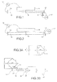
- a beam-type piezoresistive strain gauge 11 is integral with the beam-type resonator 10 and is placed perpendicular to it at a location close to one of the two recesses 12 and 13.
- the fixed excitation electrode 14 of the resonator 10 is brought to an alternating voltage with respect to it using 15. When the resonator is excited, it vibrates in the plane, as illustrated by the double arrow 16.
- a person skilled in the art is able to better position the detection strain gauge on the vibrating beam by, for example, performing a finite element simulation of the structure (via conventional software of the ANSYS, Coventor, ... type). . It seeks for this the optimum position tending to maximize the stress exerted on the strain gauge detection for a given deflection of the vibrating beam.
- the excitation of the resonance of the resonator 10 can be done by means of electrostatic means, or by means of piezoelectric means, thermal or electromagnetic, conventionally used by those skilled in the art.
- the measurement of the stress of the piezoresistive gauge 11 can be done between the recess 12 of the resonator 10 and the end of the beam of the gauge 11 by means of conventional measuring means 17.
- the resistance measurement can be done using a Wheatstone bridge.
- the device of the invention is a simple resonator, in which the piezoresistive strain gauge 11 is placed parallel to the resonator 10 at a point as far as possible from the neutral line, and close to the recess 12 .
- the device of the invention is then a sensor composed of two "cascade" test bodies, which are respectively the resonator and the piezoresistive strain gauge.
- the resonator is associated with an element likely to cause a variation in its characteristics (stress, modification of the effective mass) as a function of the quantity to be measured.
- the quantity to be measured (acceleration, rotation, pressure, ...) thus exerts on the resonator a constraint which is proportional to it.
- This constraint has the effect of modifying the limiting conditions of the resonator, which results in a modification of its resonant frequency or amplitude of vibration.
- the vibration measurement, by deformation of the resonator is then measured by the piezoelectric strain gauge, which is integral with the resonator, but which is not part of it.
- a - planar resonant accelerometer with piezoresistive gage detection according to the invention
- a simple Wheatstone bridge assembly with a single sensing element is shown on the Figures 3A and 3B .
- this assembly comprises a resonator 30 fixed on the one hand to a recess 31 and on the other hand to a seismic mass 32, and a fixed excitation electrode 36.
- a piezoresistive strain gauge 33 is placed perpendicular to the resonator, in one place close to the recess 31.
- the seismic mass 32 is also fixed to a recess 34 by means of a hinge 35.
- the resistance measurement R + dR or R (1 + ⁇ ) of the strain gauge 33 is performed by measuring a voltage difference between the points A and B, as illustrated in FIGS. Figures 3A and 3B , with three resistors R and a generator E.
- the values of the strain gages 33 and 33 ' are respectively R + dR (or R (1 + ⁇ )) and R-dR (or R (1- ⁇ )).
- This constraint value can be easily evaluated by a finite element simulation (ANSYS or Coventor software for example).
- the variation of resistance is therefore proportional to the displacement of the resonator (that is to say its vibration). So we can go back to resonance frequency of the resonator through the resistance measurement of the piezoresistive gauges.
- the figure 5 illustrates a Wheatstone bridge differential gyro.
- the gyroscope 50 consists of a support, not shown, and two seismic masses 51, 52 which are movable in the plane (X, Y) of the support, and which can vibrate.
- Two connecting arms 53, 54 movable relative to the support and parallel to each other, are connected to the moving masses by means of bending arms 55, 56, 57 and 58 having sufficient flexibility to allow the relative movements of the two masses. 51, 52 relative to the connecting arms, while being sufficiently rigid to transmit the movements of these two masses to the link arms.
- the connecting arms 53 and 54 and the bending arms 55, 56, 57 and 58 form a rectangular frame.
- Means are provided to put the masses 51 and 52 in vibration in the plane (X, Y) of the support, for example excitation combs 60, 61 interlocking in one or both sides of each mobile mass 51, 52 These combs 60, 61 generate, via electrostatic forces, a reciprocating movement of each mass in a first direction X, here from left to right of the sheet.
- Other means can be envisaged, such as electromagnetic excitation.
- the masses 51, 52 are excited, preferably at the resonance or in the vicinity of the resonance, by means of electrostatic forces applied via inter-digit comb structures 60, 61: the set of masses 51, 52 and link means 53, 54, 55, 56, 57 and 58 thus form an excitation resonator.
- the resonance operation makes it possible to obtain a high amplitude of displacement, and a large quality factor, increasing the sensitivity of the gyrometer.
- the vibration of the masses is in phase opposition, that is to say that their movements are in the opposite direction at each instant: the distance separating the two masses is variable, this variation being tolerated by the bending arms.
- Each link arm 53 or 54 is connected firstly to a first end of a piezoresistive strain gauge 63 or 64 arranged perpendicular to it, the other end of which is connected to a recess 65 or 66, and to a hinge 67 or 68 whose other end is connected to a recess 69 or 70.
- the angle ⁇ corresponds to the rotation of the masses at the hinges 67 and 68, under the effect of the rotation ⁇ (effect of the Coriolis force).
- the voltage measured between the points A and B of the Wheatstone bridge makes it possible to know the variation of resistance dR, and thus the angular velocity ⁇ .
- a piezoresistive gauge 85, a resonator 86, a hinge 87, an excitation electrode of the resonator 88, and a seismic mass 89 are thus obtained.
- the suspended piezoresistive gauges may be silicon nanowires. This slightly changes the succession of steps presented above (the nanowires being neither more nor less than silicon beams of very small section, typically 100 ⁇ 100 nm 2 , which can be made by ebeam lithography for example).
- the big advantage is that these nanowires have the property of having giant piezoresistive coefficients, as described in the referenced document [5], hence potentially increased sensor sensitivity.
- the piezoresistive gauge consists of two parallel branches 11 'and 11 "brought together so that they see practically the same constraint (typically with 2 to 10 micrometers spacing) In this case, the resistance measurement is made between the two branches 11 'and 11 "of the gauge.
Landscapes
- Physics & Mathematics (AREA)
- General Physics & Mathematics (AREA)
- Engineering & Computer Science (AREA)
- Radar, Positioning & Navigation (AREA)
- Remote Sensing (AREA)
- Computer Hardware Design (AREA)
- Manufacturing & Machinery (AREA)
- Microelectronics & Electronic Packaging (AREA)
- Acoustics & Sound (AREA)
- Gyroscopes (AREA)
- Micromachines (AREA)
- Measuring Fluid Pressure (AREA)
- Pressure Sensors (AREA)
Applications Claiming Priority (1)
| Application Number | Priority Date | Filing Date | Title |
|---|---|---|---|
| FR0755992A FR2917731B1 (fr) | 2007-06-25 | 2007-06-25 | Dispositif resonant a detection piezoresistive realise en technologies de surface |
Publications (3)
| Publication Number | Publication Date |
|---|---|
| EP2008965A2 true EP2008965A2 (de) | 2008-12-31 |
| EP2008965A3 EP2008965A3 (de) | 2013-10-23 |
| EP2008965B1 EP2008965B1 (de) | 2020-07-01 |
Family
ID=39092575
Family Applications (1)
| Application Number | Title | Priority Date | Filing Date |
|---|---|---|---|
| EP08158743.8A Active EP2008965B1 (de) | 2007-06-25 | 2008-06-23 | Resonanzvorrichtung mit piezoelektrischer Erfassung für den Einsatz in Oberflächentechnologien |
Country Status (4)
| Country | Link |
|---|---|
| US (1) | US8156807B2 (de) |
| EP (1) | EP2008965B1 (de) |
| JP (1) | JP5543085B2 (de) |
| FR (1) | FR2917731B1 (de) |
Cited By (15)
| Publication number | Priority date | Publication date | Assignee | Title |
|---|---|---|---|---|
| EP2211143A1 (de) * | 2009-01-23 | 2010-07-28 | Commissariat à l'Énergie Atomique et aux Énergies Alternatives | Planarer mikromechanischer Kreisel mit Messung ausserhalb der Ebene mittels Dehnungsmesser |
| WO2011110295A1 (de) * | 2010-03-10 | 2011-09-15 | Fraunhofer-Gesellschaft Zur Förderung Der Angewandten Forschung E.V. Angewandten Forschung E.V. | Piezoresistiver wandler |
| EP2405238A1 (de) * | 2010-07-07 | 2012-01-11 | Commissariat À L'Énergie Atomique Et Aux Énergies Alternatives | Trägheitssensor zum Erfassen der Drehbewegungen einer oszillierenden Scheibe |
| FR2964653A1 (fr) * | 2010-09-13 | 2012-03-16 | Commissariat Energie Atomique | Dispositif resonant a actionnement dans le plan, et procede de fabrication du dispositif |
| WO2012034990A1 (fr) | 2010-09-13 | 2012-03-22 | Commissariat à l'énergie atomique et aux énergies alternatives | Dispositif resonant, a detection piezoresistive et a resonateur relie de facon elastique au support du dispositif, et procede de fabrication de celui-ci |
| WO2012034951A1 (fr) | 2010-09-13 | 2012-03-22 | Commissariat à l'énergie atomique et aux énergies alternatives | Dispositif a poutre suspendue et moyens de detection piezoresistive du deplacement de celle-ci, et procede de fabrication du dispositif |
| WO2013001081A1 (fr) * | 2011-06-30 | 2013-01-03 | Centre National De La Recherche Scientifique (C.N.R.S) | Dispositif resisitif a jauge de contrainte a nanofils de silicium et procede d'optimisation de la consommation electrique d'un tel dispositif |
| US8371166B2 (en) | 2009-01-23 | 2013-02-12 | Commissariat A L'energie Atomique | Inertial or resonating sensor in surface technology, with out of plane detection by strain gauge |
| FR2995995A1 (fr) * | 2012-09-26 | 2014-03-28 | Sagem Defense Securite | Capteur de pression a base de nanojauges couplees a un resonateur |
| FR2996219A1 (fr) * | 2012-10-02 | 2014-04-04 | Commissariat Energie Atomique | Systeme de mesure comprenant un reseau de resonateurs de type nano-systeme electromecanique |
| EP2878942A1 (de) | 2013-12-02 | 2015-06-03 | California Institute Of Technology | System und Verfahren zur Untersuchung eines Gases |
| WO2019158878A1 (fr) | 2018-02-19 | 2019-08-22 | Apix Analytics | Détecteur pour la chromatographie en phase gazeuse |
| WO2019158879A1 (fr) | 2018-02-19 | 2019-08-22 | Apix Analytics | Procede d'analyse d'hydrocarbures |
| CN111181490A (zh) * | 2020-01-02 | 2020-05-19 | 西安交通大学 | 一种基于超谐同步技术的硅微谐振式倍频器 |
| FR3158794A1 (fr) | 2024-01-31 | 2025-08-01 | Apix Analytics | Dispositif d’analyse de gaz |
Families Citing this family (17)
| Publication number | Priority date | Publication date | Assignee | Title |
|---|---|---|---|---|
| FR2924422B1 (fr) * | 2007-11-30 | 2009-12-25 | Commissariat Energie Atomique | Dispositif a detection par jauge de contrainte piezoresistive suspendue comportant une cellule d'amplification de contrainte. |
| FR2941534B1 (fr) * | 2009-01-26 | 2011-12-23 | Commissariat Energie Atomique | Capteur de champ magnetique a jauge de contrainte suspendue |
| FR2948114B1 (fr) * | 2009-07-17 | 2012-03-30 | Commissariat Energie Atomique | Nems comportant des moyens de transduction a base d'alliage d'aluminium |
| FR2951826B1 (fr) | 2009-10-23 | 2012-06-15 | Commissariat Energie Atomique | Capteur a detection piezoresistive dans le plan |
| EP2341618A1 (de) * | 2009-12-23 | 2011-07-06 | Nxp B.V. | Piezoresistiver MEMS-Resonator |
| FR2957414B1 (fr) | 2010-03-15 | 2012-09-28 | Commissariat Energie Atomique | Capteur de force a bruit reduit |
| US8604574B2 (en) * | 2011-05-03 | 2013-12-10 | International Business Machines Corporation | Transparent photodetector |
| FR2992066B1 (fr) * | 2012-06-15 | 2014-07-11 | Commissariat Energie Atomique | Capteur de champ magnetique a force de laplace |
| CN102798387B (zh) * | 2012-09-07 | 2016-03-02 | 中北大学 | 一种soi基巨压阻效应微陀螺 |
| FR2995690B1 (fr) | 2012-09-19 | 2015-04-10 | Commissariat Energie Atomique | Capteur de flux thermique a element vibrant et capteur de gaz comportant au moins un tel capteur |
| FR2995692B1 (fr) | 2012-09-19 | 2014-10-10 | Commissariat Energie Atomique | Capteur de flux thermique a resolution augmentee |
| FR2995691B1 (fr) * | 2012-09-19 | 2014-10-10 | Commissariat Energie Atomique | Capteur de flux thermique, capteur de gaz comportant au moins un tel capteur et jauge pirani comportant au moins un tel capteur |
| FR3012805A1 (fr) | 2013-11-06 | 2015-05-08 | Commissariat Energie Atomique | Dispositif mems/nems comportant un reseau de resonateurs a actionnement electrostatique et a reponse frequentielle ajustable, notamment pour filtre passe-bande |
| EP3136052B1 (de) | 2015-08-31 | 2021-03-24 | Commissariat à l'Énergie Atomique et aux Énergies Alternatives | Resonante vorrichtung zur piezoresistiven detektion, insbesondere mit grosser schwingungsamplitude |
| CN108490216A (zh) * | 2018-01-31 | 2018-09-04 | 嘉兴市纳杰微电子技术有限公司 | 一种硅微谐振式加速度计 |
| FR3094708B1 (fr) * | 2019-04-08 | 2022-12-02 | Commissariat Energie Atomique | Charniere hors-plan pour structure micromecanique et/ou nanomecanique a sensibilite aux contraintes internes reduite |
| CN110207863B (zh) * | 2019-06-04 | 2020-06-02 | 北京化工大学 | 提高纳米电阻式力学传感器稳定性的方法及系统 |
Citations (1)
| Publication number | Priority date | Publication date | Assignee | Title |
|---|---|---|---|---|
| US20060032306A1 (en) | 2004-08-13 | 2006-02-16 | Commissariat A L'energie Atomique | Micro-gyrometer with frequency detection |
Family Cites Families (12)
| Publication number | Priority date | Publication date | Assignee | Title |
|---|---|---|---|---|
| JPH0472530A (ja) * | 1990-07-13 | 1992-03-06 | Yokogawa Electric Corp | 振動式トランスデューサ |
| JPH05118905A (ja) * | 1991-09-25 | 1993-05-14 | Yokogawa Electric Corp | 振動形センサ |
| JP3186975B2 (ja) * | 1995-04-12 | 2001-07-11 | センソノール・エイ・エス | 力センサー |
| US6316796B1 (en) * | 1995-05-24 | 2001-11-13 | Lucas Novasensor | Single crystal silicon sensor with high aspect ratio and curvilinear structures |
| DE19812773C2 (de) * | 1998-03-24 | 2002-11-14 | Conti Temic Microelectronic | Mikrosensor mit einer Resonatorstruktur |
| DE19845185B4 (de) * | 1998-10-01 | 2005-05-04 | Eads Deutschland Gmbh | Sensor mit Resonanzstruktur sowie Vorrichtung und Verfahren zum Selbsttest eines derartigen Sensors |
| GB0116393D0 (en) * | 2001-07-05 | 2001-08-29 | Druck Ltd | Improved sensor |
| JP3969228B2 (ja) * | 2002-07-19 | 2007-09-05 | 松下電工株式会社 | 機械的変形量検出センサ及びそれを用いた加速度センサ、圧力センサ |
| US7302856B2 (en) * | 2003-05-07 | 2007-12-04 | California Institute Of Technology | Strain sensors based on nanowire piezoresistor wires and arrays |
| JP2006086318A (ja) * | 2004-09-16 | 2006-03-30 | Citizen Watch Co Ltd | 電気機械変換器とその製造方法 |
| JP2007147556A (ja) * | 2005-11-30 | 2007-06-14 | Canon Inc | 薄膜及び薄膜の製造方法およびその薄膜を用いた化学センサ |
| US7819005B2 (en) * | 2007-06-25 | 2010-10-26 | Micron Technology, Inc. | Sensor and transducer devices comprising carbon nanotubes, methods of making and using the same |
-
2007
- 2007-06-25 FR FR0755992A patent/FR2917731B1/fr active Active
-
2008
- 2008-06-20 US US12/214,627 patent/US8156807B2/en active Active
- 2008-06-23 EP EP08158743.8A patent/EP2008965B1/de active Active
- 2008-06-24 JP JP2008164830A patent/JP5543085B2/ja active Active
Patent Citations (1)
| Publication number | Priority date | Publication date | Assignee | Title |
|---|---|---|---|---|
| US20060032306A1 (en) | 2004-08-13 | 2006-02-16 | Commissariat A L'energie Atomique | Micro-gyrometer with frequency detection |
Non-Patent Citations (4)
| Title |
|---|
| DAZHONH JIN ET AL.: "High-mode resonant piezoresistive cantilever sensors for tens-fentogram resoluble mass sensing in air", J. MICROMECH., vol. 16, 2006, pages 1017 - 1023 |
| JASPER EKHUND, E; SHKEL, A.M.: "Single-mask SOI fabrication process for linear and angular piezoresistive accelerometers with on-chip reference resistors", 2005 IEEE, 30 October 2005 (2005-10-30), pages 656 - 659 |
| K. RECK ET AL.: "Piezoresistive effect in top-down fabricated silicon nanowires", MEMS 2008, 13 January 2008 (2008-01-13) |
| M. AIBELE ET AL.: "Resonant accelerometer with self- test", SENSORS AND ACTUATORS, vol. A92, 2001, pages 161 - 167 |
Cited By (33)
| Publication number | Priority date | Publication date | Assignee | Title |
|---|---|---|---|---|
| US8371166B2 (en) | 2009-01-23 | 2013-02-12 | Commissariat A L'energie Atomique | Inertial or resonating sensor in surface technology, with out of plane detection by strain gauge |
| FR2941525A1 (fr) * | 2009-01-23 | 2010-07-30 | Commissariat Energie Atomique | Gyrometre en technologie de surface, a detection hors plan par jauge de contrainte. |
| EP2211143A1 (de) * | 2009-01-23 | 2010-07-28 | Commissariat à l'Énergie Atomique et aux Énergies Alternatives | Planarer mikromechanischer Kreisel mit Messung ausserhalb der Ebene mittels Dehnungsmesser |
| US8375788B2 (en) | 2009-01-23 | 2013-02-19 | Commissariat A L'energie Atomique | Gyrometer in surface technology, with out-of-plane detection by strain gauge |
| WO2011110295A1 (de) * | 2010-03-10 | 2011-09-15 | Fraunhofer-Gesellschaft Zur Förderung Der Angewandten Forschung E.V. Angewandten Forschung E.V. | Piezoresistiver wandler |
| US9063167B2 (en) | 2010-03-10 | 2015-06-23 | Fraunhofer-Gesellschaft Zur | Piezoresistive transducer |
| FR2962532A1 (fr) * | 2010-07-07 | 2012-01-13 | Commissariat Energie Atomique | Capteur inertiel de rotations a disque oscillant |
| US9010193B2 (en) | 2010-07-07 | 2015-04-21 | Commissariat A L' Energie Atomique Et Aux Energies Alternatives | Inertial sensor having an oscillating rotating disk |
| EP2405238A1 (de) * | 2010-07-07 | 2012-01-11 | Commissariat À L'Énergie Atomique Et Aux Énergies Alternatives | Trägheitssensor zum Erfassen der Drehbewegungen einer oszillierenden Scheibe |
| WO2012034990A1 (fr) | 2010-09-13 | 2012-03-22 | Commissariat à l'énergie atomique et aux énergies alternatives | Dispositif resonant, a detection piezoresistive et a resonateur relie de facon elastique au support du dispositif, et procede de fabrication de celui-ci |
| WO2012034951A1 (fr) | 2010-09-13 | 2012-03-22 | Commissariat à l'énergie atomique et aux énergies alternatives | Dispositif a poutre suspendue et moyens de detection piezoresistive du deplacement de celle-ci, et procede de fabrication du dispositif |
| WO2012034949A1 (fr) | 2010-09-13 | 2012-03-22 | Commissariat à l'énergie atomique et aux énergies alternatives | Dispositif resonant a actionnement dans le plan, et procede de fabrication du dispositif |
| FR2964653A1 (fr) * | 2010-09-13 | 2012-03-16 | Commissariat Energie Atomique | Dispositif resonant a actionnement dans le plan, et procede de fabrication du dispositif |
| US9293686B2 (en) | 2010-09-13 | 2016-03-22 | Commissariat a l'énergie atomique et aux énergies alternatives | In-plane actuated resonant device and method of manufacturing the device |
| WO2013001081A1 (fr) * | 2011-06-30 | 2013-01-03 | Centre National De La Recherche Scientifique (C.N.R.S) | Dispositif resisitif a jauge de contrainte a nanofils de silicium et procede d'optimisation de la consommation electrique d'un tel dispositif |
| FR2977318A1 (fr) * | 2011-06-30 | 2013-01-04 | Centre Nat Rech Scient | Dispositif resisitif a jauge de contrainte a nanofils de silicium et procede d'optimisation de la consommation electrique d'un tel dispositif |
| US9134191B2 (en) | 2011-06-30 | 2015-09-15 | Centre National De La Recherche Scientifique | Resistive device comprising a silicon-nanowire-comprising strain gauge and method for optimizing the electrical consumption of such a device |
| US9726562B2 (en) | 2012-09-26 | 2017-08-08 | Sagem Defense Securite | Pressure sensor made from nanogauges coupled to a resonator |
| WO2014049062A1 (fr) * | 2012-09-26 | 2014-04-03 | Sagem Defense Securite | Capteur de pression a base de nanojauges couplees a un resonateur |
| FR2995995A1 (fr) * | 2012-09-26 | 2014-03-28 | Sagem Defense Securite | Capteur de pression a base de nanojauges couplees a un resonateur |
| RU2623694C1 (ru) * | 2012-09-26 | 2017-06-28 | Сажем Дефанс Секюрите | Датчик давления, выполненный на основе нанотензометров, связанных с резонатором |
| FR2996219A1 (fr) * | 2012-10-02 | 2014-04-04 | Commissariat Energie Atomique | Systeme de mesure comprenant un reseau de resonateurs de type nano-systeme electromecanique |
| WO2014053575A1 (fr) * | 2012-10-02 | 2014-04-10 | Commissariat A L'energie Atomique Et Aux Energies Alternatives | Systeme de mesure comprenant un reseau de resonateurs de type nano-systeme electromecanique |
| US9945822B2 (en) | 2012-10-02 | 2018-04-17 | Commissariat A L'energie Atomique Et Aux Energies Alternatives | Measurement system including a network of nanoelectromechanical system resonators |
| EP2878942A1 (de) | 2013-12-02 | 2015-06-03 | California Institute Of Technology | System und Verfahren zur Untersuchung eines Gases |
| WO2015082956A1 (en) | 2013-12-02 | 2015-06-11 | Commissariat A L'energie Atomique Et Aux Energies Alternatives | System and method for analyzing a gas |
| US10175212B2 (en) | 2013-12-02 | 2019-01-08 | California Institute Of Technology | System and method for analyzing a gas |
| WO2019158878A1 (fr) | 2018-02-19 | 2019-08-22 | Apix Analytics | Détecteur pour la chromatographie en phase gazeuse |
| WO2019158879A1 (fr) | 2018-02-19 | 2019-08-22 | Apix Analytics | Procede d'analyse d'hydrocarbures |
| CN111181490A (zh) * | 2020-01-02 | 2020-05-19 | 西安交通大学 | 一种基于超谐同步技术的硅微谐振式倍频器 |
| CN111181490B (zh) * | 2020-01-02 | 2022-02-11 | 西安交通大学 | 一种基于超谐同步技术的硅微谐振式倍频器 |
| FR3158794A1 (fr) | 2024-01-31 | 2025-08-01 | Apix Analytics | Dispositif d’analyse de gaz |
| WO2025163172A1 (fr) | 2024-01-31 | 2025-08-07 | Apix Analytics | Dispositif d'analyse de gaz |
Also Published As
| Publication number | Publication date |
|---|---|
| US8156807B2 (en) | 2012-04-17 |
| FR2917731A1 (fr) | 2008-12-26 |
| EP2008965A3 (de) | 2013-10-23 |
| FR2917731B1 (fr) | 2009-10-23 |
| US20080314148A1 (en) | 2008-12-25 |
| EP2008965B1 (de) | 2020-07-01 |
| JP2009002953A (ja) | 2009-01-08 |
| JP5543085B2 (ja) | 2014-07-09 |
Similar Documents
| Publication | Publication Date | Title |
|---|---|---|
| EP2008965B1 (de) | Resonanzvorrichtung mit piezoelektrischer Erfassung für den Einsatz in Oberflächentechnologien | |
| EP2211185B1 (de) | Trägheitssensor oder Resonanzsensor in der Oberflächentechnologie zur Erkennung von Abweichungen mit Hilfe eines Dehnungsmessers | |
| EP2367015B1 (de) | Rauscharmer kraftsensor | |
| EP2065713B1 (de) | Erfassungsvorrichtung mittels aufgehängtem Dehnungsmesser mit piezoelektrischem Widerstand, der eine Dehnungsverstärkungszelle umfasst | |
| EP2211143B1 (de) | Planarer mikromechanischer Kreisel mit Messung ausserhalb der Ebene mittels Dehnungsmesser | |
| EP1626282B1 (de) | Mikrokreisel mit Frequenzdetektion | |
| EP2541222B1 (de) | Druckmessgerät mit optimierter Emfpindlichkeit | |
| EP1840582B1 (de) | Resonanter Trägheitsmikrosensor variabler Dicke, der im Bereich der Oberflächentechnologien eingesetzt wird | |
| EP2617129B1 (de) | Vorrichtung mit freihängendem träger und piezoresistive vorrichtung zur verlagerungserkennung | |
| EP2617130B1 (de) | Resonanter piezoresistiver detektor mit einem an das trägerelement des detektors elastisch angeschlossenen resonator und verfahren zur herstellung dieses detektors | |
| EP2405238B1 (de) | Trägheitssensor zum Erfassen der Drehbewegungen einer oszillierenden Scheibe | |
| EP3599469B1 (de) | Beschleunigungssensor mit dehnungsmessstreifen mit verbesserter präzision | |
| WO2012085456A2 (fr) | Structure planaire pour gyromètre tri-axe | |
| EP3766830B1 (de) | Mechanische verbindung für mechanische mems- und nems-struktur, und mems- und nems-struktur, die eine solche mechanische verbindung umfasst | |
| EP2815210A1 (de) | Kompakte vorrichtung zur erfassung mindestens einer beschleunigung und einer drehzahl | |
| EP3394564B1 (de) | System zur aufhängung einer beweglichen masse mit vorrichtung zur verbindung der beweglichen masse mit optimierter linearität | |
| EP2949621B1 (de) | Kapazitive mikro- und/ oder nanoelektronische Vorrichtung mit erhöhter Kompaktheit | |
| EP2862000B1 (de) | Sensor für magnetfelder mit laplace-kraft | |
| EP4148432B1 (de) | Mikroelektromechanischer resonanzsensor mit entkopplungsmasse zwischen resonator und testmasse |
Legal Events
| Date | Code | Title | Description |
|---|---|---|---|
| PUAI | Public reference made under article 153(3) epc to a published international application that has entered the european phase |
Free format text: ORIGINAL CODE: 0009012 |
|
| AK | Designated contracting states |
Kind code of ref document: A2 Designated state(s): AT BE BG CH CY CZ DE DK EE ES FI FR GB GR HR HU IE IS IT LI LT LU LV MC MT NL NO PL PT RO SE SI SK TR |
|
| AX | Request for extension of the european patent |
Extension state: AL BA MK RS |
|
| RAP1 | Party data changed (applicant data changed or rights of an application transferred) |
Owner name: COMMISSARIAT A L'ENERGIE ATOMIQUE ET AUX ENERGIES |
|
| PUAL | Search report despatched |
Free format text: ORIGINAL CODE: 0009013 |
|
| AK | Designated contracting states |
Kind code of ref document: A3 Designated state(s): AT BE BG CH CY CZ DE DK EE ES FI FR GB GR HR HU IE IS IT LI LT LU LV MC MT NL NO PL PT RO SE SI SK TR |
|
| AX | Request for extension of the european patent |
Extension state: AL BA MK RS |
|
| RIC1 | Information provided on ipc code assigned before grant |
Ipc: H03H 9/02 20060101ALI20130917BHEP Ipc: G01C 19/00 20130101ALI20130917BHEP Ipc: B81B 3/00 20060101AFI20130917BHEP Ipc: G01L 1/18 20060101ALI20130917BHEP Ipc: G01P 15/097 20060101ALI20130917BHEP Ipc: G01P 15/08 20060101ALI20130917BHEP |
|
| 17P | Request for examination filed |
Effective date: 20131127 |
|
| RBV | Designated contracting states (corrected) |
Designated state(s): AT BE BG CH CY CZ DE DK EE ES FI FR GB GR HR HU IE IS IT LI LT LU LV MC MT NL NO PL PT RO SE SI SK TR |
|
| AKX | Designation fees paid |
Designated state(s): DE FR GB |
|
| STAA | Information on the status of an ep patent application or granted ep patent |
Free format text: STATUS: EXAMINATION IS IN PROGRESS |
|
| 17Q | First examination report despatched |
Effective date: 20171207 |
|
| GRAP | Despatch of communication of intention to grant a patent |
Free format text: ORIGINAL CODE: EPIDOSNIGR1 |
|
| STAA | Information on the status of an ep patent application or granted ep patent |
Free format text: STATUS: GRANT OF PATENT IS INTENDED |
|
| INTG | Intention to grant announced |
Effective date: 20191114 |
|
| RIN1 | Information on inventor provided before grant (corrected) |
Inventor name: ROBERT, PHILIPPE |
|
| GRAJ | Information related to disapproval of communication of intention to grant by the applicant or resumption of examination proceedings by the epo deleted |
Free format text: ORIGINAL CODE: EPIDOSDIGR1 |
|
| STAA | Information on the status of an ep patent application or granted ep patent |
Free format text: STATUS: EXAMINATION IS IN PROGRESS |
|
| GRAP | Despatch of communication of intention to grant a patent |
Free format text: ORIGINAL CODE: EPIDOSNIGR1 |
|
| INTC | Intention to grant announced (deleted) | ||
| STAA | Information on the status of an ep patent application or granted ep patent |
Free format text: STATUS: GRANT OF PATENT IS INTENDED |
|
| INTG | Intention to grant announced |
Effective date: 20200123 |
|
| RIC1 | Information provided on ipc code assigned before grant |
Ipc: G01P 15/08 20060101ALI20200110BHEP Ipc: H03H 9/02 20060101ALI20200110BHEP Ipc: G01P 15/097 20060101ALI20200110BHEP Ipc: G01C 19/00 20130101ALI20200110BHEP Ipc: G01C 19/574 20120101ALI20200110BHEP Ipc: G01C 19/5769 20120101ALI20200110BHEP Ipc: B81B 3/00 20060101AFI20200110BHEP Ipc: G01L 1/18 20060101ALI20200110BHEP Ipc: G01C 19/5755 20120101ALI20200110BHEP |
|
| GRAS | Grant fee paid |
Free format text: ORIGINAL CODE: EPIDOSNIGR3 |
|
| GRAA | (expected) grant |
Free format text: ORIGINAL CODE: 0009210 |
|
| STAA | Information on the status of an ep patent application or granted ep patent |
Free format text: STATUS: THE PATENT HAS BEEN GRANTED |
|
| AK | Designated contracting states |
Kind code of ref document: B1 Designated state(s): DE FR GB |
|
| REG | Reference to a national code |
Ref country code: GB Ref legal event code: FG4D Free format text: NOT ENGLISH |
|
| REG | Reference to a national code |
Ref country code: DE Ref legal event code: R096 Ref document number: 602008062907 Country of ref document: DE |
|
| REG | Reference to a national code |
Ref country code: DE Ref legal event code: R097 Ref document number: 602008062907 Country of ref document: DE |
|
| PLBE | No opposition filed within time limit |
Free format text: ORIGINAL CODE: 0009261 |
|
| STAA | Information on the status of an ep patent application or granted ep patent |
Free format text: STATUS: NO OPPOSITION FILED WITHIN TIME LIMIT |
|
| 26N | No opposition filed |
Effective date: 20210406 |
|
| PGFP | Annual fee paid to national office [announced via postgrant information from national office to epo] |
Ref country code: DE Payment date: 20250618 Year of fee payment: 18 |
|
| PGFP | Annual fee paid to national office [announced via postgrant information from national office to epo] |
Ref country code: GB Payment date: 20250625 Year of fee payment: 18 |
|
| PGFP | Annual fee paid to national office [announced via postgrant information from national office to epo] |
Ref country code: FR Payment date: 20250623 Year of fee payment: 18 |