EP2008968A1 - Dispositif de reaction - Google Patents
Dispositif de reaction Download PDFInfo
- Publication number
- EP2008968A1 EP2008968A1 EP07740899A EP07740899A EP2008968A1 EP 2008968 A1 EP2008968 A1 EP 2008968A1 EP 07740899 A EP07740899 A EP 07740899A EP 07740899 A EP07740899 A EP 07740899A EP 2008968 A1 EP2008968 A1 EP 2008968A1
- Authority
- EP
- European Patent Office
- Prior art keywords
- reaction
- catalyst
- fluid
- water
- reaction fluid
- Prior art date
- Legal status (The legal status is an assumption and is not a legal conclusion. Google has not performed a legal analysis and makes no representation as to the accuracy of the status listed.)
- Granted
Links
Images


Classifications
-
- C—CHEMISTRY; METALLURGY
- C01—INORGANIC CHEMISTRY
- C01B—NON-METALLIC ELEMENTS; COMPOUNDS THEREOF; METALLOIDS OR COMPOUNDS THEREOF NOT COVERED BY SUBCLASS C01C
- C01B3/00—Hydrogen; Gaseous mixtures containing hydrogen; Separation of hydrogen from mixtures containing it; Purification of hydrogen; Reversible storage of hydrogen
- C01B3/02—Production of hydrogen; Production of gaseous mixtures containing hydrogen
- C01B3/32—Production of hydrogen; Production of gaseous mixtures containing hydrogen by reaction of gaseous or liquid organic compounds with gasifying agents, e.g. water, carbon dioxide or air
- C01B3/323—Catalytic reaction of gaseous or liquid organic compounds other than hydrocarbons with gasifying agents
- C01B3/326—Catalytic reaction of gaseous or liquid organic compounds other than hydrocarbons with gasifying agents characterised by the catalysts
-
- B—PERFORMING OPERATIONS; TRANSPORTING
- B01—PHYSICAL OR CHEMICAL PROCESSES OR APPARATUS IN GENERAL
- B01J—CHEMICAL OR PHYSICAL PROCESSES, e.g. CATALYSIS OR COLLOID CHEMISTRY; THEIR RELEVANT APPARATUS
- B01J16/00—Chemical processes in general for reacting liquids with non- particulate solids, e.g. sheet material; Apparatus specially adapted therefor
- B01J16/005—Chemical processes in general for reacting liquids with non- particulate solids, e.g. sheet material; Apparatus specially adapted therefor in the presence of catalytically active bodies, e.g. porous plates
-
- B—PERFORMING OPERATIONS; TRANSPORTING
- B01—PHYSICAL OR CHEMICAL PROCESSES OR APPARATUS IN GENERAL
- B01J—CHEMICAL OR PHYSICAL PROCESSES, e.g. CATALYSIS OR COLLOID CHEMISTRY; THEIR RELEVANT APPARATUS
- B01J23/00—Catalysts comprising metals or metal oxides or hydroxides, not provided for in group B01J21/00
- B01J23/70—Catalysts comprising metals or metal oxides or hydroxides, not provided for in group B01J21/00 of the iron group metals or copper
- B01J23/74—Iron group metals
- B01J23/755—Nickel
-
- C—CHEMISTRY; METALLURGY
- C01—INORGANIC CHEMISTRY
- C01B—NON-METALLIC ELEMENTS; COMPOUNDS THEREOF; METALLOIDS OR COMPOUNDS THEREOF NOT COVERED BY SUBCLASS C01C
- C01B2203/00—Integrated processes for the production of hydrogen or synthesis gas
- C01B2203/02—Processes for making hydrogen or synthesis gas
- C01B2203/0205—Processes for making hydrogen or synthesis gas containing a reforming step
- C01B2203/0227—Processes for making hydrogen or synthesis gas containing a reforming step containing a catalytic reforming step
- C01B2203/0233—Processes for making hydrogen or synthesis gas containing a reforming step containing a catalytic reforming step the reforming step being a steam reforming step
-
- C—CHEMISTRY; METALLURGY
- C01—INORGANIC CHEMISTRY
- C01B—NON-METALLIC ELEMENTS; COMPOUNDS THEREOF; METALLOIDS OR COMPOUNDS THEREOF NOT COVERED BY SUBCLASS C01C
- C01B2203/00—Integrated processes for the production of hydrogen or synthesis gas
- C01B2203/10—Catalysts for performing the hydrogen forming reactions
- C01B2203/1005—Arrangement or shape of catalyst
- C01B2203/1011—Packed bed of catalytic structures, e.g. particles, packing elements
- C01B2203/1017—Packed bed of catalytic structures, e.g. particles, packing elements characterised by the form of the structure
-
- C—CHEMISTRY; METALLURGY
- C01—INORGANIC CHEMISTRY
- C01B—NON-METALLIC ELEMENTS; COMPOUNDS THEREOF; METALLOIDS OR COMPOUNDS THEREOF NOT COVERED BY SUBCLASS C01C
- C01B2203/00—Integrated processes for the production of hydrogen or synthesis gas
- C01B2203/10—Catalysts for performing the hydrogen forming reactions
- C01B2203/1005—Arrangement or shape of catalyst
- C01B2203/1035—Catalyst coated on equipment surfaces, e.g. reactor walls
-
- C—CHEMISTRY; METALLURGY
- C01—INORGANIC CHEMISTRY
- C01B—NON-METALLIC ELEMENTS; COMPOUNDS THEREOF; METALLOIDS OR COMPOUNDS THEREOF NOT COVERED BY SUBCLASS C01C
- C01B2203/00—Integrated processes for the production of hydrogen or synthesis gas
- C01B2203/12—Feeding the process for making hydrogen or synthesis gas
- C01B2203/1205—Composition of the feed
- C01B2203/1211—Organic compounds or organic mixtures used in the process for making hydrogen or synthesis gas
- C01B2203/1217—Alcohols
-
- Y—GENERAL TAGGING OF NEW TECHNOLOGICAL DEVELOPMENTS; GENERAL TAGGING OF CROSS-SECTIONAL TECHNOLOGIES SPANNING OVER SEVERAL SECTIONS OF THE IPC; TECHNICAL SUBJECTS COVERED BY FORMER USPC CROSS-REFERENCE ART COLLECTIONS [XRACs] AND DIGESTS
- Y02—TECHNOLOGIES OR APPLICATIONS FOR MITIGATION OR ADAPTATION AGAINST CLIMATE CHANGE
- Y02P—CLIMATE CHANGE MITIGATION TECHNOLOGIES IN THE PRODUCTION OR PROCESSING OF GOODS
- Y02P20/00—Technologies relating to chemical industry
- Y02P20/50—Improvements relating to the production of bulk chemicals
- Y02P20/52—Improvements relating to the production of bulk chemicals using catalysts, e.g. selective catalysts
Definitions
- the present invention relates to a reaction device used for producing water gas from polyhydric alcohol and water and to a water gas production method which is carried out using the reaction device.
- Glycerin is a raw material produced as a byproduct in production of bio-diesel fuel, practical use of which in the future has been expected. Glycerin is derived from a natural product called carbon neutral and has higher significance under current energy-related circumstances in view of environmental protection.
- the produced hydrogen is applicable to chemical materials for fuel cells, hydrogen-added reactions, etc., and fuel sources for hydrogen vehicles.
- non-patent document 1 it has been reported in non-patent document 1 that the types of catalyst metals which are excellent in steam reforming from glycerin have been studied using a fixed bed reactor.
- non-patent document 2 the possibility of producing hydrogen from glycerin using nickel catalyst in a subcritical water field has been reported.
- the methods disclosed in non-patent documents 1 and 2 can produce hydrogen at a certain level of purity but are not satisfactory in production as to the time necessary for reaction and yield.
- Patent document 1 discloses a microreactor for reforming a raw material to produce hydrogen gas.
- the microreactor has a metal substrate having microgrooves on its one surface, a heating element set on the other surface of the metal substrate via an insulation film, a catalyst carried in the microgrooves, and a cover member having a raw material inlet and a gas outlet and joined to the metal substrate so as to cover the microgrooves.
- Patent document 2 discloses a chemical reaction apparatus having a continuous reaction path.
- the chemical reaction apparatus includes: a temperature adjustment layer which corresponds to a region including the reaction paths and supplies a certain quantity of heat; a first electrode layer formed in a first region over the temperature adjustment layer; an insulating layer formed in a second region other than the first region over the temperature adjustment layer; and a second electrode layer lying over the first electrode layer for supplying power via the first electrode layer to produce a certain quantity of heat in the temperature adjustment layer, wherein the insulating layer is integral with the first electrode layer and is made of an insulating material obtained by oxidizing a conductive material of the first electrode layer.
- a reaction device of the present invention is for use in production of water gas from polyhydric alcohol and water, the device including a reactor which has a reaction field where a catalyst is provided inside and a reaction fluid flows, wherein the catalyst has a surface extending in a direction of flow of the reaction fluid.
- a water gas production method of the present invention is for producing water gas from polyhydric alcohol and water, including the step of producing water gas by supplying a reaction fluid containing polyhydric alcohol and water to flow in a reaction field provided with catalyst which has a surface extending in a direction of flow of the reaction fluid such that a reaction of polyhydric alcohol and water occurs.
- FIG. 1 shows a reaction device 10 according to Embodiment 1.
- the reaction device 10 is a continuous type reactor capable of continuously producing a reaction product.
- the reaction device 10 includes a pipe extending from a reaction fluid supplier 11 , which is a reaction fluid source, to a product reservoir 15 .
- the reaction device 10 also includes a fluid supplying pump 12 and reactor 13 which are provided in series at some midpoints in the pipe in this order when viewed from the upper reach to the lower reach with a certain interval between the pump 12 and the reactor 13 .
- the reaction device 10 further includes a heater 16 which is provided such that the heater 16 can heat the reactor 13 .
- the reaction device 10 is used for production of water gas, wherein: a reaction fluid, particularly a mixture of polyhydric alcohol (e.g., glycerin, propanediol, or the like) as the raw material and water, is supplied from the reaction fluid supplier 11 to the reactor 13 via the fluid supplying pump 12 ; polyhydric alcohol and water are reacted in the reactor 13 so that water gas is produced; and the reaction fluid containing the produced water gas is stored in the product reservoir 15 .
- a reaction fluid particularly a mixture of polyhydric alcohol (e.g., glycerin, propanediol, or the like) as the raw material and water
- polyhydric alcohol e.g., glycerin, propanediol, or the like
- the reactor 13 has an inlet through which the reaction fluid enters and an outlet through which the reaction fluid exits.
- the reactor 13 also has a reaction path 13a inside the reactor 13 between the inlet and the outlet.
- the reaction path 13a has the form of an elongated hole.
- the reaction path 13a constitutes a reaction field 14 in which the reaction fluid flows through and reacts.
- the reaction path 13a of the reactor 13 may be formed such that a flat member which has a groove formed in its surface by cutting or any other processing is tightly joined with another flat member.
- the reaction path 13a may be formed by a tubular member already complete, such as a square tube, circular tube, or the like.
- the cross-sectional shape of the reaction path 13a may be, for example, circular, semicircular, elliptic, semielliptic, square, rectangular, trapezoidal, parallelogramic, indeterminate, etc.
- the longitudinal passage of the reaction path 13a between the inlet and the outlet may have a linear shape, circular shape, meander shape, spiral shape, etc.
- the area of the cross section of the reaction path 13a encompassed by the cross-sectional perimeter, converted to an equivalent diameter, is preferably from 0.05 mm to 50 mm.
- the reaction in the reaction path 13a is highly endothermic and, in view of achieving such a highly-endothermic reaction more desirably, the cross-sectional area of the reaction path 13a is more preferably from 0.05 mm to 10 mm, even more preferably from 0.1 mm to 3 mm, with which the thermal conductivity can be improved.
- the "equivalent diameter” means the diameter of a perfect circle which has an area equal to the cross-sectional area of the reaction path 13a .
- the reaction path 13a which constitutes the reaction field 14 is provided with catalyst 17 .
- the catalyst 17 has a surface extending in the direction of flow of the reaction fluid.
- the catalyst 17 include metals applicable for steam reforming of alcohol. Of these metals, any of the metals of Group 8 to Group 12, preferably any of the metals of Group 8 to Group 10, may be industrially suitable.
- the specific examples of the catalyst include iron, cobalt, nickel, copper, zinc, ruthenium, rhodium, palladium, osmium, iridium, and platinum. Of these examples, the metals of Group 8 to Group 10 are preferable in view of industrial cost, availability and safety. More preferably, the catalyst is nickel, ruthenium, palladium, or platinum. As a matter of course, some of these examples may be used together. Alternatively, the catalyst may be used with the oxidation state of its surface being controlled by a pretreatment, such as reduction with hydrogen or the like, oxidation with oxygen or air, etc.
- the catalyst 17 is in the form of, for example, an elongated structure, e.g., a linear structure, such as a metal wire, a bundle of wires, or a stranded cable, or an elongated plate structure.
- the catalyst 17 constitutes the inner wall of the reaction path 13a inside the reactor 13 .
- the catalyst 17 may have a shape continuously extending in the direction of flow of the reaction fluid.
- the catalyst 17 may have separate parts aligned with intervals in the direction of flow of the reaction fluid.
- the outer surface corresponds to a surface extending in the direction of flow of the reaction fluid.
- the reactor 13 having the reaction path 13a formed by flat members may have the catalyst 17 in the groove formed in one of the flat members.
- the reactor 13 having the reaction path 13a formed by a tubular member already complete may have the catalyst 17 inserted in the reaction path 13a .
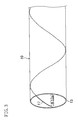
- the catalyst 17 may be provided in the reaction path 13a in the form of a spiral at a certain pitch in the direction of flow of the reaction fluid as shown in FIG. 3 .
- parts of catalyst metal may be aligned with intervals in the direction of flow of the reaction fluid such that the catalyst metal parts as a whole constitute a surface extending in the direction of flow of the reaction fluid.
- the catalyst 17 may be provided entirely across the whole reach of the reactor 13 between the inlet and the outlet or may be provided partially over the reach of the reactor 13 between the inlet and the outlet, and any of these arrangements is possible.
- the surface of the inner wall corresponds to the surface extending in the direction of flow of the reaction fluid.
- a metal which constitutes the inner wall of the reaction path 13a may be a catalyst metal.
- the inner wall of the reaction path 13a may be coated with the catalyst 17 by plating, sputtering, painting plus drying, or any other technique after general construction of the reaction path 13a .
- the inner wall may be partially formed by a catalyst metal such that the catalyst metal parts of the wall occur with intervals in the direction of flow of the reaction fluid.
- the catalyst 17 may be provided entirely across the whole reach of the reactor 13 between the inlet and the outlet or may be provided partially over the reach of the reactor 13 between the inlet and the outlet, and any of these arrangements is possible.
- An applicable index indicative that the catalyst 17 has a surface extending in the direction of flow of the reaction fluid is "A/S" where S is the surface area of a unit of catalyst and A is the projected area of the unit of catalyst on a plane perpendicular to the direction of flow of the reaction fluid.
- A/S 0.1(-).
- a particle having an indeterminate shape is deemed to have the form of an elliptical sphere which holds the maximum length values in the x, y and z axes, such that the values of the surface area and projected area of a unit of particle obtained from this elliptical shape can be used for examination.
- ⁇ A/ ⁇ S (where ⁇ S is the total sum of surface areas S of catalyst units and ⁇ A is the total sum of projected areas A of the catalyst units) can be used as the aforementioned index. It should be noted that, in this specification, the total sums are represented by ⁇ A and ⁇ S even in a case where the reaction device only has one catalyst unit.
- ⁇ A/ ⁇ S is preferably 0 to 0.2(-), more preferably 0 to 0.1(-), even more preferably 0 to 0.07(-), and even more preferably 0 to 0.05(-).
- the catalyst 17 is preferably provided in the reaction path 13a such that, in any traverse section of the reaction path 13a, the catalyst 17 exists in the area of radius of 10 mm. More preferably, the catalyst 17 exists in the area of radius of 5 mm. With such an arrangement, the distance between the reaction fluid and the catalyst 17 is 20 mm or less at any location in the reaction field 14 , so that desirable reactivity and aldehyde selectivity are achieved.
- the reaction path 13a may be in the form of an elongated slit wherein the inner wall is formed by the catalyst 17 and a traverse section has a space of 20 mm or less.
- the reaction path 13a is preferably structured such that the reaction fluid flows smoothly in the vicinity of the catalyst 17 without stagnation. If without a stagnation region (i.e., dead space) in the vicinity of the catalyst 17 , the reaction residence time distribution of the reaction fluid can be narrowed, whereby the reaction fluid residing for a long time is prevented from causing a side reaction, such as carbonization, or the like.
- the catalyst 17 is preferably located such that the catalyst units do not have a point contact with each other or have narrow gaps between each other.
- the minimum distance between catalyst units is preferably 0.2 mm or more, more preferably 0.5 mm or more, even more preferably 1 mm or more. It should be noted that a reactor called “microreactor” has a narrow flow path smaller than 1 mm, and in such a case, the minimum distance between catalyst units is not limited to the ranges mentioned above so long as no stagnation occurs in the flow path.
- the fluid supplying pump 12 supplies the reaction fluid output from the reaction fluid supplier 11 to the reactor 13 .
- the fluid supplying pump 12 for liquid reaction fluid include a volute pump, diffuser pump, volute diagonal pump, diagonal pump, axial flow pump, gear pump, screw pump, cam pump, vane pump, piston pump, plunger pump, diaphragm pump, vortex flow pump, viscosity pump, airlift pump, jet pump, electromagnetic pump, etc.
- a pump which generates small pulsating flow is preferably.
- reaction fluid may be supplied to the reactor 13 by means of pressure difference instead of using the fluid supplying pump 12 .
- Examples of the heating system of the heater 16 include a heat exchange method by means of a heated medium, such as hot oil, vapor, etc., a heat transfer method via contact or radiation with a heating element, such as an electric heater, or the like, a method which utilizes a heat pump, etc.
- each of the components of the reaction device 10 is preferably made of a metal material.
- the metal material include single-element metals, such as aluminum, titanium, chromium, iron, cobalt, nickel, copper, zinc, zirconium, etc., and alloys multiply containing these single-element metals.
- alloys include austenite steels represented by SUS304 and SUS316, martensite steels represented by SUS420, two-phase stainless steels of ferrite and austenite represented by SUS329, Ni alloys represented by Hastelloy C276 and Inconel 600, titanium alloys represented by 6-4 titanium alloy, etc.
- each of the components can be made of one of these materials solely or can be made of two or more of these materials together.
- the water gas production method of this embodiment uses polyhydric alcohol and water to produce a mixture gas of hydrogen and carbon monoxide which is called water gas.
- the polyhydric alcohol refers to a compound having such a structure that has a carbon number of 2 or more and has two or more hydroxyls bonded thereto. So long as this structure is satisfied, a group other than hydroxyl, for example, a carboxylic acid group, aldehyde group, or the like, may be bonded thereto.
- polyhydric alcohol examples include dihydric alcohols, such as ethylene diglycol, 1,2-propanediol, 1,3-propanediol, 2,3-hydroxypropanal, 1,2-butanediol, 1,3-butanediol, 1,4-butanediol, tartaric acid, and the like, trihydric alcohols, such as glycerin, 1,2,4-butanetriol, 1,2,6-hexanetriol, and the like, and tetrahydric alcohols, such as pentaerythritol, and the like.
- dihydric alcohols such as ethylene diglycol, 1,2-propanediol, 1,3-propanediol, 2,3-hydroxypropanal, 1,2-butanediol, 1,3-butanediol, 1,4-butanediol, tartaric acid, and the like
- trihydric alcohols such as glycerin, 1,2,
- the polyhydric alcohol generates water gas based on Formula (1) shown below. It should be noted that the produced carbon monoxide reacts with water based on the water gas shift reaction of Formula (2) to secondarily produce hydrogen.
- a reaction fluid i.e., a mixture of polyhydric alcohol (raw material) and water, is supplied from the reaction fluid supplier 11 to the reactor 13 via the fluid supplying pump 12 .
- the phase state of the reaction fluid may be any of liquid, gas, and supercritical fluid or may be a mixed state of these phases.
- the phase state of the reaction fluid is controlled by adjusting the heating temperature of the reactor 13 heated by the heater 16 and setting the pressure of the reaction fluid by a pressure regulator provided upstream of the product reservoir 15.
- the mix ratio of polyhydric alcohol and water in the reaction fluid is preferably such that the molar ratio of water to carbon atoms included in polyhydric alcohol is from 0.3 to 10, more preferably 1 to 6.
- the mix ratio of glycerin and water in the reaction fluid is, in view of desirable progress of reaction, preferably such that the molar ratio of water to glycerin is 0.9 to 30, more preferably 3 to 18.
- any material other than polyhydric alcohol and water may be mixed in the reaction fluid as necessary so long as the reactivity and yield are not deteriorated.
- the material which can be mixed in the reaction fluid include the gases of nitrogen, argon, helium, oxygen, carbon dioxide, etc.
- the reaction fluid may contain, in addition to polyhydric alcohol and water, an organic compound which does not deteriorate essential reactivity, such as an organic acid, hydrocarbon, alcohol or aldehyde, or a salt thereof, or an inorganic salt which does not deteriorate essential reactivity.
- polyhydric alcohol and water react in the reactor 13 to produce water gas.
- the reaction time of polyhydric alcohol and water of the reaction fluid is preferably about 0.1 second to 1 hour, more preferably 1 second to 10 minutes.
- the reaction time of glycerin and water of the reaction fluid is preferably about 0.1 second to 1 hour, more preferably 1 second to 10 minutes.
- the reaction time of propanediol and water of the reaction fluid is preferably about 0.1 second to 1 hour, more preferably 1 second to 10 minutes.
- the reaction time of polyhydric alcohol and water of the reaction fluid is determined by the residence time of the reaction fluid in the reactor 13 and is therefore controlled by setting the feeding speed of the reaction fluid from the fluid supplying pump 12 according to the volume of the reaction field 14 .
- the reaction temperature of polyhydric alcohol and water of the reaction fluid is preferably 200°C to 1000°C, more preferably 300°C to 700°C.
- the reaction temperature of glycerin and water of the reaction fluid is preferably 200°C to 1000°C, more preferably 300°C to 700°C.
- the reaction temperature of propanediol and water of the reaction fluid is preferably about 200°C to 1000°C, more preferably 300°C to 700°C.
- the reaction temperature of polyhydric alcohol and water of the reaction fluid is controlled by adjusting the heating temperature of the reactor 13 heated by the heater 16 .
- the reaction fluid containing produced water gas is stored in the product reservoir 15 .
- the stored water gas is purified to have the qualities required by the use thereof, for example, fuel cell, hydrogen engine fuel, chemical material, etc.
- the purification of water gas may be achieved by means of, e.g., a gas-permeable membrane, PSA, or the like.
- FIG. 4 shows a reaction device 10 according to Embodiment 2.
- the elements having the same names as those of Embodiment 1 are denoted by the same reference numerals as those of Embodiment 1.
- the reaction device 10 is a continuous type reactor capable of continuously producing a reaction product.
- the reaction device 10 includes a pipe extending from a reaction fluid supplier 11 to a product reservoir 15 .
- the reaction device 10 also includes a fluid supplying pump 12, a preheating section 18 , a reactor 13 , and a cooler 19 which are provided in series at some midpoints in the pipe in this order when viewed from the upper reach to the lower reach with intervals therebetween.
- the reaction device 10 further includes a heater 16 which is provided such that the heater 16 can heat the preheating section 18 and the reactor 13.
- the reaction device 10 is used for production of water gas, wherein: a reaction fluid, particularly a mixture of polyhydric alcohol (e.g., glycerin, propanediol, or the like) as the raw material and water, is supplied from the reaction fluid supplier 11 to the preheating section 18 via the fluid supplying pump 12 ; the reaction fluid preheated by the preheating section 18 is supplied to the reactor 13 ; polyhydric alcohol and water react in the reactor 13 to produce water gas; the reaction fluid containing the produced water gas is cooled by the cooler 19 ; and the cooled reaction fluid is stored in the product reservoir 15.
- a reaction fluid particularly a mixture of polyhydric alcohol (e.g., glycerin, propanediol, or the like) as the raw material and water
- a reaction fluid particularly a mixture of polyhydric alcohol (e.g., glycerin, propanediol, or the like) as the raw material and water
- a reaction fluid particularly a mixture of polyhydric alcohol (e.
- the water gas production method of Embodiment 2 also uses polyhydric alcohol and water, as in Embodiment 1, to produce a mixture gas of hydrogen and carbon monoxide which is called water gas.
- the reaction fluid preheated in the preheating section 18 is supplied to the reactor 13 .
- the preheating time of the reaction fluid is preferably 0.1 second to 1 hour, more preferably 1 second to 10 minutes.
- the preheating time of the reaction fluid is preferably 0.1 second to 1 hour, more preferably 1 second to 10 minutes.
- polyhydric alcohol is propanediol
- the preheating time of the reaction fluid is preferably 0.1 second to 1 hour, more preferably 1 second to 10 minutes.
- the preheating time of the reaction fluid is determined by the residence time of the reaction fluid in the preheating section 18 and therefore can be controlled by selection of the capacity of the preheating section 18 . If the capacity of the preheating section 18 is fixed, the preheating time of the reaction fluid is controlled by setting the feeding speed of the reaction fluid from the fluid supplying pump 12 .
- the preheating temperature of the reaction fluid is preferably 200°C to 1000°C, more preferably 300°C to 700°C.
- the preheating temperature of the reaction fluid is preferably 200°C to 1000°C, more preferably 300°C to 700°C.
- polyhydric alcohol is propanediol
- the preheating temperature of the reaction fluid is preferably 200°C to 1000°C, more preferably 300°C to 700°C.
- the preheating temperature of the reaction fluid is simultaneously controlled by adjusting the heating temperature of the reactor 13 heated by the heater 16 .
- the reaction fluid containing water gas produced in the reactor 13 is cooled by the cooler 19 .
- the cooling time of the reaction fluid is preferably 0.1 second to 1 hour, more preferably 1 second to 10 minutes.
- the cooling time of the reaction fluid is determined by the residence time of the reaction fluid in the cooler 19 and therefore can be controlled by selection of the capacity of the cooler 19. If the capacity of the cooler 19 is fixed, the cooling time of the reaction fluid is controlled by setting the feeding speed of the reaction fluid from the fluid supplying pump 12.
- the post-cooling temperature of the reaction fluid is preferably 0°C to 200°C, more preferably 20°C to 100°C.
- the post-cooling temperature of the reaction fluid is controlled by setting the cooling temperature of the reaction fluid in the cooler 19 .
- Sampled liquid was subjected to gas chromatography analysis to quantitatively measure the concentration of unreacted raw material.
- the product by multiplication of the measured concentration and the quantity of the sampled liquid represents the quantity of unreacted raw material.
- the value of 100% minus the percentage of the quantity of unreacted raw material relative to the amount of the supplied raw material represents the reaction consumption rate.
- Sampled gas was subjected to gas chromatography analysis to quantitatively measure the concentration of respective gas components including hydrogen, carbon monoxide, carbon dioxide, etc.
- the quantity of water gas i.e., the total of quantity of hydrogen and carbon monoxide which were determined from the products by multiplication of the concentration of the gas components and the quantity of the sampled gas, was calculated.
- the ratio of the quantity of actually-produced water gas to the quantity of water gas theoretically determined from the quantity of supplied raw material for reaction was taken as the yield of water gas. It should be noted that the amount of water gas theoretically produceable from 1 mol of glycerin is 7 mol.
- the amount of water gas theoretically produceable from 1 mol of 1,2-propanediol is 5 mol.
- the amount of water gas theoretically produceable from 1 mol of 1-propanol is 6 mol.
- Sampled gas was subjected to gas chromatography analysis to quantitatively measure the concentration of respective gas components which contain carbon atoms, e.g., carbon monoxide, carbon dioxide, methane, ethane, ethylene, propane, propylene, and the like.
- the mole number of each of the gas components was calculated from the product by multiplication of the measured concentration of the gas component and the quantity of the sampled gas.
- the sampled liquid was subjected to gas chromatography analysis to quantitatively measure the unreacted raw material and the reaction product and determine the mole numbers thereof.
- the mole numbers of the respective components were converted to the mole numbers of carbon atoms included in the respective components and summed together.
- the value of 100% minus the percentage of the sum of the mole numbers of the carbon atom relative to the mole number of the carbon atom converted from the quantity of raw material supplied for reaction was taken as the carbon residual rate.
- the carbon residual rate With a high carbon residual rate, there is a possibility of inducing occlusion of the reactor or deactivation of the activity of catalyst. Thus, smaller carbon residual rate is more desirable for stable production of water gas.
- the reaction device of Example 1 is the same as that shown in FIG. 4 .
- the fluid supplying pump is a microfeeder
- the preheating section is made of SUS316 and has a circular tube flow path with inside diameter of 1.0 mm and length of 2 m
- the reactor is made of nickel (nickel purity>99.0%) and has a circular tube flow path with inside diameter of 2.18 mm and length of 0.10 m
- the cooler is of air-cooling type, is made of SUS316, and has a circular tube flow path with inside diameter of 1.0 mm and length of 0.5 m
- the heater is an electric furnace of radial heat transmitting type capable of heating the preheating section and the reactor to and maintaining them at 600°C.
- the inner wall of the reactor constitutes a metal catalyst layer.
- This reaction device was subjected to pre-reaction treatment A such that the device was heated to and maintained at 600°C for one hour with hydrogen flowed therethrough.
- a solution prepared in advance by mixing 36.2 g of glycerin (manufactured by Kishida Chemical Co., Ltd., special grade) and 63.8 g of distilled water (manufactured by Wako Pure Chemical Industries, Ltd.) was supplied as the reaction fluid by the microfeed pump at 0.218 mL/h to the preheating section.
- the reaction fluid from the cooler containing mixed gas and liquid, was sampled in a Tedlar bag.
- the liquid composition and gas composition of the sampled reaction fluid were separately analyzed.
- the composition of the sampled gas is shown in TABLE 1.
- the yield of the water gas was 76.6%.
- the carbon residual rate was 0%.
- the nickel wires are unstranded and extend substantially in parallel with the fluid flow path of the reactor.
- ⁇ A/ ⁇ S was 2.5 ⁇ 10 -4 where ⁇ S is the total sum of surface areas S of catalyst and ⁇ A is the total sum of projected areas A on a plane perpendicular to the direction of flow of the reaction fluid.
- This reaction device was subjected to pre-reaction treatment A such that the device was heated to and maintained at 600°C for one hour with hydrogen flowed therethrough.
- a solution prepared in advance by mixing 36.2 g of glycerin (manufactured by Kishida Chemical Co., Ltd., special grade) and 63.8 g of distilled water (manufactured by Wako Pure Chemical Industries, Ltd.) was supplied as the reaction fluid by the microfeed pump at 0.136 mL/h to the preheating section.
- the reaction fluid from the cooler containing mixed gas and liquid, was sampled in a Tedlar bag.
- the liquid composition and gas composition of the sampled reaction fluid were separately analyzed.
- the composition of the sampled gas is shown in TABLE 1.
- the yield of the water gas was 71.0%.
- the carbon residual rate was 4.9%.
- the reaction device of Example 3 is the same as that of Example 1 except that the preheating section is made of SUS316 and has a circular tube flow path with inside diameter of 1.0 mm and length of 1 m and that the reactor is made of nickel (nickel purity>99.0%) and has a circular tube flow path with inside diameter of 4.35 mm and length of 0.10 m.
- This reaction device was subjected to pre-reaction treatment A such that the device was heated to and maintained at 600°C for one hour with hydrogen flowed therethrough.
- the reaction fluid from the cooler containing mixed gas and liquid, was sampled in a Tedlar bag.
- the liquid composition and gas composition of the sampled reaction fluid were separately analyzed.
- the reaction device of Example 4 is the same as that of Example 3.
- This reaction device was subjected to pre-reaction treatment A such that the device was heated to and maintained at 600°C for one hour with hydrogen flowed therethrough.
- a solution prepared in advance by mixing 36.2 g of glycerin (manufactured by Kishida Chemical Co., Ltd., special grade) and 63.8 g of distilled water (manufactured by Wako Pure Chemical Industries, Ltd.) was supplied as the reaction fluid by the microfeed pump at 0.867 mL/h to the preheating section.
- the reaction fluid from the cooler containing mixed gas and liquid, was sampled in a Tedlar bag.
- the liquid composition and gas composition of the sampled reaction fluid were separately analyzed.
- the composition of the sampled gas is shown in TABLE 1.
- the yield of the water gas was 91.0%.
- the carbon residual rate was 4.8%.
- the reaction device of Example 5 is the same as that of Example 3 except that the reactor is made of nickel, has a circular tube flow path with inside diameter of 4.35 mm and length of 0.10 m, and is plated with platinum.
- the inner wall of the reactor constitutes a metal catalyst layer.
- This reaction device was subjected to pre-reaction treatment B such that residues were removed from the surface of the inner wall, and then, the device was heated to and maintained at 600°C for three hours with hydrogen flowed therethrough.
- a solution prepared in advance by mixing 36.2 g of glycerin (manufactured by Kishida Chemical Co., Ltd., special grade) and 63.8 g of distilled water (manufactured by Wako Pure Chemical Industries, Ltd.) was supplied as the reaction fluid by the microfeed pump at 0.867 mL/h to the preheating section.
- the reaction fluid from the cooler containing mixed gas and liquid, was sampled in a Tedlar bag.
- the liquid composition and gas composition of the sampled reaction fluid were separately analyzed.
- the composition of the sampled gas is shown in TABLE 1.
- the yield of the water gas was 78.4%.
- the carbon residual rate was 0%.
- the reaction device of Example 6 is the same as that of Example 3 except that the reactor is made of nickel, has a circular tube flow path with inside diameter of 4.35 mm and length of 0.10 m, and is plated with iridium.
- This reaction device was subjected to pre-reaction treatment B such that residues were removed from the surface of the inner wall, and then, the device was heated to and maintained at 600°C for three hours with hydrogen flowed therethrough.
- a solution prepared in advance by mixing 36.2 g of glycerin (manufactured by Kishida Chemical Co., Ltd., special grade) and 63.8 g of distilled water (manufactured by Wako Pure Chemical Industries, Ltd.) was supplied as the reaction fluid by the microfeed pump at 0.867 mL/h to the preheating section.
- the reaction fluid from the cooler containing mixed gas and liquid, was sampled in a Tedlar bag.
- the liquid composition and gas composition of the sampled reaction fluid were separately analyzed.
- the composition of the sampled gas is shown in TABLE 1.
- the yield of the water gas was 81.6%.
- the carbon residual rate was 0%.
- Example 7 The reaction device of Example 7 is the same as that of Example 3.
- This reaction device was subjected to pre-reaction treatment B such that residues were removed from the surface of the inner wall, and then, the device was heated to and maintained at 600°C for three hours with hydrogen flowed therethrough.
- a solution prepared in advance by mixing 36.2 g of glycerin (manufactured by Kishida Chemical Co., Ltd., special grade) and 63.8 g of distilled water (manufactured by Wako Pure Chemical Industries, Ltd.) was supplied as the reaction fluid by the microfeed pump at 0.867 mL/h to the preheating section.
- the reaction fluid from the cooler containing mixed gas and liquid, was sampled in a Tedlar bag.
- the liquid composition and gas composition of the sampled reaction fluid were separately analyzed.
- the composition of the sampled gas is shown in TABLE 1.
- the yield of the water gas was 88.7%.
- the carbon residual rate was 0%.
- the reaction device of Comparative Example 1 is the same as that of Example 2 except that the metal catalyst in the reaction path of the reactor is 0.9442 g of nickel powder (manufactured by Wako Pure Chemical Industries, Ltd.) having the particle size of 150 ⁇ m or less instead of the nickel wires.
- ⁇ A/ ⁇ S was 0.25 where ⁇ S is the total sum of surface areas S of catalyst and ⁇ A is the total sum of projected areas A on a plane perpendicular to the direction of flow of the reaction fluid.
- This reaction device was subjected to pre-reaction treatment A such that the device was heated to and maintained at 600°C for one hour with hydrogen flowed therethrough.
- a solution prepared in advance by mixing 36.2 g of glycerin (manufactured by Kishida Chemical Co., Ltd., special grade) and 63.8 g of distilled water (manufactured by Wako Pure Chemical Industries, Ltd.) was supplied as the reaction fluid by the microfeed pump at 0.083 mL/h to the preheating section.
- the reaction fluid from the cooler containing mixed gas and liquid, was sampled in a Tedlar bag.
- the liquid composition and gas composition of the sampled reaction fluid were separately analyzed.
- the composition of the sampled gas is shown in TABLE 1.
- the yield of the water gas was 55.6%.
- the carbon residual rate was 21.5%.
- the reaction device of Comparative Example 2 is the same as that of Example 2 except that the reactor is a tube made of SUS316 having a linear reaction path with inside diameter of 2.18 mm and length of 0.10 m and that the metal catalyst in the reaction path is 0.1036 g of platinum black powder (manufactured by Wako Pure Chemical Industries, Ltd.) having the particle size of 2 ⁇ m or less (observed by human eyes through optical microscope) instead of the nickel wires.
- ⁇ A/ ⁇ S was 0.25 where ⁇ S is the total sum of surface areas S of catalyst and ⁇ A is the total sum of projected areas A on a plane perpendicular to the direction of flow of the reaction fluid.
- This reaction device was subjected to pre-reaction treatment A such that the device was heated to and maintained at 600°C for one hour with hydrogen flowed therethrough.
- a solution prepared in advance by mixing 36.2 g of glycerin (manufactured by Kishida Chemical Co., Ltd., special grade) and 63.8 g of distilled water (manufactured by Wako Pure Chemical Industries, Ltd.) was supplied as the reaction fluid by the microfeed pump at 0.193 mL/h to the preheating section.
- the reaction fluid from the cooler containing mixed gas and liquid, was sampled in a Tedlar bag.
- the liquid composition and gas composition of the sampled reaction fluid were separately analyzed.
- the reaction device of Comparative Example 3 is the same as that of Example 3.
- This reaction device was subjected to pre-reaction treatment A such that the device was heated to and maintained at 600°C for one hour with hydrogen flowed therethrough.
- the reaction fluid from the cooler containing mixed gas and liquid, was sampled in a Tedlar bag.
- the liquid composition and gas composition of the sampled reaction fluid were separately analyzed.
- TABLE 1 shows the structure of the reaction path and other details of the reactor of the reaction devices used in Examples 1 to 7 and Comparative Examples 1 to 3 and the test evaluation results.
- the present invention is useful for a reaction device used in production of water gas from polyhydric alcohol and water and a water gas production method carried out using the reaction device.
Landscapes
- Chemical & Material Sciences (AREA)
- Organic Chemistry (AREA)
- Chemical Kinetics & Catalysis (AREA)
- Health & Medical Sciences (AREA)
- General Health & Medical Sciences (AREA)
- Engineering & Computer Science (AREA)
- Combustion & Propulsion (AREA)
- Inorganic Chemistry (AREA)
- Organic Low-Molecular-Weight Compounds And Preparation Thereof (AREA)
- Hydrogen, Water And Hydrids (AREA)
- Physical Or Chemical Processes And Apparatus (AREA)
- Catalysts (AREA)
Applications Claiming Priority (2)
| Application Number | Priority Date | Filing Date | Title |
|---|---|---|---|
| JP2006104117 | 2006-04-05 | ||
| PCT/JP2007/057463 WO2007114438A1 (fr) | 2006-04-05 | 2007-04-03 | Dispositif de reaction |
Publications (3)
| Publication Number | Publication Date |
|---|---|
| EP2008968A1 true EP2008968A1 (fr) | 2008-12-31 |
| EP2008968A4 EP2008968A4 (fr) | 2012-02-29 |
| EP2008968B1 EP2008968B1 (fr) | 2017-08-30 |
Family
ID=38563702
Family Applications (1)
| Application Number | Title | Priority Date | Filing Date |
|---|---|---|---|
| EP07740899.5A Ceased EP2008968B1 (fr) | 2006-04-05 | 2007-04-03 | Méthode de production de gaz à l'eau |
Country Status (5)
| Country | Link |
|---|---|
| US (1) | US8114174B2 (fr) |
| EP (1) | EP2008968B1 (fr) |
| JP (1) | JP5143560B2 (fr) |
| CN (1) | CN101321690B (fr) |
| WO (1) | WO2007114438A1 (fr) |
Cited By (2)
| Publication number | Priority date | Publication date | Assignee | Title |
|---|---|---|---|---|
| EP2117697A1 (fr) * | 2007-01-31 | 2009-11-18 | Kao Corporation | Dispositif de réaction |
| EP2500315A4 (fr) * | 2009-11-12 | 2013-11-06 | Kao Corp | Procédé de production de gaz aqueux |
Families Citing this family (5)
| Publication number | Priority date | Publication date | Assignee | Title |
|---|---|---|---|---|
| JP2009298616A (ja) * | 2008-06-11 | 2009-12-24 | Ihi Corp | グリセリン改質装置および改質方法 |
| JP5396749B2 (ja) * | 2008-06-11 | 2014-01-22 | 株式会社Ihi | グリセリン改質装置および改質方法 |
| JP5330808B2 (ja) | 2008-11-14 | 2013-10-30 | 花王株式会社 | 水性ガス用原料 |
| KR101634513B1 (ko) * | 2013-03-29 | 2016-06-28 | 제이에프이 스틸 가부시키가이샤 | 고발열량 가스의 제조 방법 |
| KR102143571B1 (ko) | 2013-07-02 | 2020-08-12 | 다이킨 고교 가부시키가이샤 | 전해질 용액 및 그 제조 방법, 연속 용해 장치, 전해질막, 전극 촉매층, 막 전극 접합체, 및 연료 전지 |
Family Cites Families (12)
| Publication number | Priority date | Publication date | Assignee | Title |
|---|---|---|---|---|
| CA1008667A (en) * | 1972-06-30 | 1977-04-19 | Foster Wheeler Corporation | Catalytic steam reforming |
| DE3663652D1 (en) * | 1985-03-05 | 1989-07-06 | Ici Plc | Steam reforming hydrocarbons |
| DE69808521T2 (de) * | 1998-07-21 | 2003-01-30 | Haldor Topsoee A/S, Lyngby | Synthesegasherstellung durch dampfreformierung |
| US6436354B1 (en) * | 1998-12-11 | 2002-08-20 | Uop Llc | Apparatus for generation of pure hydrogen for use with fuel cells |
| WO2001012312A2 (fr) * | 1999-08-17 | 2001-02-22 | Battelle Memorial Institute | Reacteur chimique et procede permettant de conduire des reactions catalytiques avec des reactifs en phase gazeuse |
| DE10109983A1 (de) * | 2000-03-07 | 2001-12-13 | Klug Karl H | Elektrokatalytischer Reformer für die Synthesegaserzeugung |
| MXPA04001280A (es) * | 2001-08-11 | 2004-05-27 | Texaco Development Corp | Procesadores de combustible que utilizan enfriamiento con tubos isotermicos. |
| JP2004063131A (ja) | 2002-07-25 | 2004-02-26 | Casio Comput Co Ltd | 化学反応装置及び燃料電池システム並びにその製造方法 |
| JP4414780B2 (ja) | 2003-02-06 | 2010-02-10 | 大日本印刷株式会社 | 水素製造用のマイクロリアクターおよびその製造方法 |
| KR100570752B1 (ko) * | 2004-02-26 | 2006-04-12 | 삼성에스디아이 주식회사 | 연료 전지 시스템의 개질기 및 이를 채용한 연료 전지시스템 |
| JP4580664B2 (ja) * | 2004-03-01 | 2010-11-17 | 大日本印刷株式会社 | マイクロリアクターおよびその製造方法 |
| KR100551062B1 (ko) * | 2004-06-29 | 2006-02-13 | 삼성에스디아이 주식회사 | 연료 전지 시스템, 이에 사용되는 개질기 및 그 제조 방법 |
-
2007
- 2007-04-03 US US12/226,014 patent/US8114174B2/en not_active Expired - Fee Related
- 2007-04-03 CN CN2007800005268A patent/CN101321690B/zh not_active Expired - Fee Related
- 2007-04-03 EP EP07740899.5A patent/EP2008968B1/fr not_active Ceased
- 2007-04-03 WO PCT/JP2007/057463 patent/WO2007114438A1/fr not_active Ceased
- 2007-04-03 JP JP2007537053A patent/JP5143560B2/ja not_active Expired - Fee Related
Cited By (2)
| Publication number | Priority date | Publication date | Assignee | Title |
|---|---|---|---|---|
| EP2117697A1 (fr) * | 2007-01-31 | 2009-11-18 | Kao Corporation | Dispositif de réaction |
| EP2500315A4 (fr) * | 2009-11-12 | 2013-11-06 | Kao Corp | Procédé de production de gaz aqueux |
Also Published As
| Publication number | Publication date |
|---|---|
| WO2007114438A1 (fr) | 2007-10-11 |
| JPWO2007114438A1 (ja) | 2009-08-20 |
| EP2008968B1 (fr) | 2017-08-30 |
| JP5143560B2 (ja) | 2013-02-13 |
| CN101321690A (zh) | 2008-12-10 |
| CN101321690B (zh) | 2012-03-14 |
| US8114174B2 (en) | 2012-02-14 |
| EP2008968A4 (fr) | 2012-02-29 |
| US20090249692A1 (en) | 2009-10-08 |
Similar Documents
| Publication | Publication Date | Title |
|---|---|---|
| EP2008968B1 (fr) | Méthode de production de gaz à l'eau | |
| Suryanto et al. | Rational electrode–electrolyte design for efficient ammonia electrosynthesis under ambient conditions | |
| Mhadeshwar et al. | Hierarchical multiscale mechanism development for methane partial oxidation and reforming and for thermal decomposition of oxygenates on Rh | |
| Mas et al. | A kinetic study of ethanol steam reforming using a nickel based catalyst | |
| Lattner et al. | Autothermal reforming of methanol: experiments and modeling | |
| Cao et al. | Kinetic studies of methanol steam reforming over Pd/ZnO catalyst using a microchannel reactor | |
| Butcher et al. | Design of an annular microchannel reactor (AMR) for hydrogen and/or syngas production via methane steam reforming | |
| Herdem et al. | Multiphysics modeling and heat distribution study in a catalytic microchannel methanol steam reformer | |
| Thattarathody et al. | Pressure, diffusion, and S/M ratio effects in methanol steam reforming kinetics | |
| Lim et al. | A plate-type reactor coated with zirconia-sol and catalyst mixture for methanol steam-reforming | |
| EP1770058A1 (fr) | Procédé et appareilage servant à produire du gaz reformé | |
| Raghu et al. | Microkinetic modeling and analysis of CO2 methanation on ruthenium | |
| Ha et al. | Study on the laws of methanol reforming coupled with flow, heat and mass transfer processes with variable catalyst distribution in microchannels | |
| Chen et al. | Design issues of thermally integrated methanol reforming systems for the production of hydrogen: effects of channel dimensions and catalyst properties | |
| Xu et al. | Characterization of Ni3Sn intermetallic nanoparticles fabricated by thermal plasma process and catalytic properties for methanol decomposition | |
| Huang et al. | Performance of catalysts CuO-ZnO-Al2O3, CuO-ZnO-Al2O3-Pt-Rh, and Pt-Rh in a small reformer for hydrogen generation | |
| Veriansyah et al. | Hydrogen production by gasification of isooctane using supercritical water | |
| Morillo et al. | Concept and design of a novel compact reactor for autothermal steam reforming with integrated evaporation and CO cleanup | |
| Erickson et al. | Heat transfer enhancement of steam reformation by passive flow disturbance inside the catalyst bed | |
| Schouten et al. | Miniaturization of heterogeneous catalytic reactors: Prospects for new developments in catalysis and process engineering | |
| Rogozhnikov et al. | Structured catalysts for the conversion of liquefied petroleum gas to hydrogen-rich gas and for anode off-gas afterburning | |
| Wang | Experimental studies on hydrogen generation by methane autothermal reforming over nickel-based catalyst | |
| Richard | Development and Testing of Two Lab-Scale Reactors for Electrified Steam Methane Reforming | |
| Chen | Computational Study of Transport Phenomena at the Microscale: Effects of Washcoat Thickness and Characteristic Length on the Heat and Mass Transfer Processes in Millisecond Reactors for Hydrogen Production | |
| Gaire et al. | Growing hydrogen production by merging the glycerol steam reforming and water gas shift reactions into a single reactor |
Legal Events
| Date | Code | Title | Description |
|---|---|---|---|
| PUAI | Public reference made under article 153(3) epc to a published international application that has entered the european phase |
Free format text: ORIGINAL CODE: 0009012 |
|
| 17P | Request for examination filed |
Effective date: 20081023 |
|
| AK | Designated contracting states |
Kind code of ref document: A1 Designated state(s): AT BE BG CH CY CZ DE DK EE ES FI FR GB GR HU IE IS IT LI LT LU LV MC MT NL PL PT RO SE SI SK TR |
|
| AX | Request for extension of the european patent |
Extension state: AL BA HR MK RS |
|
| RBV | Designated contracting states (corrected) |
Designated state(s): DE FR GB |
|
| A4 | Supplementary search report drawn up and despatched |
Effective date: 20120131 |
|
| RIC1 | Information provided on ipc code assigned before grant |
Ipc: B01J 16/00 20060101ALN20120125BHEP Ipc: C01B 3/32 20060101AFI20120125BHEP |
|
| DAX | Request for extension of the european patent (deleted) | ||
| 17Q | First examination report despatched |
Effective date: 20121121 |
|
| RIC1 | Information provided on ipc code assigned before grant |
Ipc: B01J 16/00 20060101ALN20170320BHEP Ipc: B01J 23/755 20060101ALI20170320BHEP Ipc: C01B 3/32 20060101AFI20170320BHEP |
|
| GRAP | Despatch of communication of intention to grant a patent |
Free format text: ORIGINAL CODE: EPIDOSNIGR1 |
|
| INTG | Intention to grant announced |
Effective date: 20170428 |
|
| GRAS | Grant fee paid |
Free format text: ORIGINAL CODE: EPIDOSNIGR3 |
|
| GRAA | (expected) grant |
Free format text: ORIGINAL CODE: 0009210 |
|
| AK | Designated contracting states |
Kind code of ref document: B1 Designated state(s): DE FR GB |
|
| REG | Reference to a national code |
Ref country code: GB Ref legal event code: FG4D |
|
| REG | Reference to a national code |
Ref country code: DE Ref legal event code: R096 Ref document number: 602007052185 Country of ref document: DE |
|
| REG | Reference to a national code |
Ref country code: FR Ref legal event code: PLFP Year of fee payment: 12 |
|
| PGFP | Annual fee paid to national office [announced via postgrant information from national office to epo] |
Ref country code: GB Payment date: 20180329 Year of fee payment: 12 |
|
| PGFP | Annual fee paid to national office [announced via postgrant information from national office to epo] |
Ref country code: FR Payment date: 20180315 Year of fee payment: 12 |
|
| REG | Reference to a national code |
Ref country code: DE Ref legal event code: R097 Ref document number: 602007052185 Country of ref document: DE |
|
| PLBE | No opposition filed within time limit |
Free format text: ORIGINAL CODE: 0009261 |
|
| STAA | Information on the status of an ep patent application or granted ep patent |
Free format text: STATUS: NO OPPOSITION FILED WITHIN TIME LIMIT |
|
| PGFP | Annual fee paid to national office [announced via postgrant information from national office to epo] |
Ref country code: DE Payment date: 20180320 Year of fee payment: 12 |
|
| 26N | No opposition filed |
Effective date: 20180531 |
|
| REG | Reference to a national code |
Ref country code: DE Ref legal event code: R119 Ref document number: 602007052185 Country of ref document: DE |
|
| GBPC | Gb: european patent ceased through non-payment of renewal fee |
Effective date: 20190403 |
|
| PG25 | Lapsed in a contracting state [announced via postgrant information from national office to epo] |
Ref country code: GB Free format text: LAPSE BECAUSE OF NON-PAYMENT OF DUE FEES Effective date: 20190403 Ref country code: DE Free format text: LAPSE BECAUSE OF NON-PAYMENT OF DUE FEES Effective date: 20191101 |
|
| PG25 | Lapsed in a contracting state [announced via postgrant information from national office to epo] |
Ref country code: FR Free format text: LAPSE BECAUSE OF NON-PAYMENT OF DUE FEES Effective date: 20190430 |