EP2009190A2 - Elément de bâtiment et procédé de fabrication - Google Patents
Elément de bâtiment et procédé de fabrication Download PDFInfo
- Publication number
- EP2009190A2 EP2009190A2 EP08011683A EP08011683A EP2009190A2 EP 2009190 A2 EP2009190 A2 EP 2009190A2 EP 08011683 A EP08011683 A EP 08011683A EP 08011683 A EP08011683 A EP 08011683A EP 2009190 A2 EP2009190 A2 EP 2009190A2
- Authority
- EP
- European Patent Office
- Prior art keywords
- layer
- carrier layer
- stiffening elements
- transverse stiffening
- building component
- Prior art date
- Legal status (The legal status is an assumption and is not a legal conclusion. Google has not performed a legal analysis and makes no representation as to the accuracy of the status listed.)
- Withdrawn
Links
Images




Classifications
-
- E—FIXED CONSTRUCTIONS
- E04—BUILDING
- E04C—STRUCTURAL ELEMENTS; BUILDING MATERIALS
- E04C2/00—Building elements of relatively thin form for the construction of parts of buildings, e.g. sheet materials, slabs, or panels
- E04C2/30—Building elements of relatively thin form for the construction of parts of buildings, e.g. sheet materials, slabs, or panels characterised by the shape or structure
- E04C2/34—Building elements of relatively thin form for the construction of parts of buildings, e.g. sheet materials, slabs, or panels characterised by the shape or structure composed of two or more spaced sheet-like parts
- E04C2/36—Building elements of relatively thin form for the construction of parts of buildings, e.g. sheet materials, slabs, or panels characterised by the shape or structure composed of two or more spaced sheet-like parts spaced apart by transversely-placed strip material, e.g. honeycomb panels
-
- E—FIXED CONSTRUCTIONS
- E04—BUILDING
- E04C—STRUCTURAL ELEMENTS; BUILDING MATERIALS
- E04C2/00—Building elements of relatively thin form for the construction of parts of buildings, e.g. sheet materials, slabs, or panels
- E04C2/02—Building elements of relatively thin form for the construction of parts of buildings, e.g. sheet materials, slabs, or panels characterised by specified materials
- E04C2/26—Building elements of relatively thin form for the construction of parts of buildings, e.g. sheet materials, slabs, or panels characterised by specified materials composed of materials covered by two or more of groups E04C2/04, E04C2/08, E04C2/10 or of materials covered by one of these groups with a material not specified in one of the groups
- E04C2/284—Building elements of relatively thin form for the construction of parts of buildings, e.g. sheet materials, slabs, or panels characterised by specified materials composed of materials covered by two or more of groups E04C2/04, E04C2/08, E04C2/10 or of materials covered by one of these groups with a material not specified in one of the groups at least one of the materials being insulating
- E04C2/296—Building elements of relatively thin form for the construction of parts of buildings, e.g. sheet materials, slabs, or panels characterised by specified materials composed of materials covered by two or more of groups E04C2/04, E04C2/08, E04C2/10 or of materials covered by one of these groups with a material not specified in one of the groups at least one of the materials being insulating composed of insulating material and non-metallic or unspecified sheet-material
Definitions
- the invention relates to a building component, in particular a wall plate, and a method for manufacturing.
- building materials such as wood, clay, stone or the like are used for building buildings.
- metals are also often used, for example, in the construction of larger warehouses using metal sheet.
- the building materials mentioned have the disadvantage that they are difficult to handle, either because of their high weight or in terms of their processing, or they do not provide sufficient heat insulation.
- Foams ie plastic-containing, foamed building materials, for example of styrofoam, offer both a high degree of thermal insulation and a very low physical density, so that they can be used to produce lightweight building components.
- the foam with one or more laminated cover layers is made into a multi-layer or composite panel to form a foam core of the composite panel.
- the breaking strength of a multilayer board produced in this way depends almost exclusively on the breaking strength of the laminated cover layers, it has the disadvantage that when the cover layers degrade, for example because of a sudden increase in temperature, the breaking strength of the entire multi-layer panel decreases. Furthermore, the kink stiffness the multi-layer plate due to the often very thin outer layers low. An important point is also the behavior of the multilayer plate in the event of extreme temperature rise, for example when fire breaks out. Should be destroyed because of this, the foam core, so the multi-layer plate and thus at worst the building formed with her collapse.
- the object of the invention is to provide a building component and a method for manufacturing, with which the structural application properties are improved.
- the object is achieved by a building component according to independent claim 1 and a method for producing a building component according to independent claim 24.
- a building component in particular a wall plate which comprises a carrier layer comprising a core of a foamed material and a cover layer which is formed on at least one side of the carrier layer on an outer surface of the carrier layer, wherein in the carrier layer transverse stiffening elements are formed ,
- a method for producing a building component comprises the following steps: forming a carrier layer with a core of a foamed material; Forming cross-bracing elements in the carrier layer; Forming a layer arrangement by arranging a cover layer on at least one side of the support layer on an outer surface of the support layer; Arranging the layer arrangement between a lower pressing surface and an upper pressing surface; and pressing the layer assembly by means of the lower pressing surface and the upper pressing surface to join the cover layer with the support layer.
- the invention offers the advantage that an increased buckling resistance and breaking strength is achieved by the transverse stiffening elements. Furthermore, the compressive and tensile strength is increased transversely to the level of the building component substantially.
- the cover layer is laminated.
- the cover layer is sealed watertight on the outer surfaces, so that a moisture absorption is reduced by the support layer or even prevented. Furthermore, a smooth surface with a correspondingly pleasant feel can be achieved in this way.
- the Querverstcifungsetti are distributed in the carrier layer grid-shaped.
- the grid must be adapted to a desired maximum load capacity for which the building component should be designed.
- the transverse stiffening elements in the carrier layer extend substantially over the entire thickness of the carrier layer, optionally up to a contact formation with the top layer. If the carrier layer melts under high heat or is decomposed for some other reason, for example due to the action of solvents, the cross-stiffening elements remain with appropriate choice of material, and can form a load-bearing structure together with the cover layer, so that, for example, in case of firebruff breakage by means of Building element c formed building does not coincide.
- transverse stiffening elements are formed as cross braces.
- the transverse stiffening elements comprise substantially cylindrical elements. This allows a simple production of the transverse stiffening elements.
- the carrier layer is formed from a material which is easy to heat, then heated tubular tools can be used to form bores in the carrier layer at the points to be provided with transverse stiffening elements, in each of which subsequently a transverse stiffening element is formed.
- the transverse stiffening elements and / or the cover layer comprise at least one material from the following group of materials: a potting compound with a fire-retardant filler, a woven material and a felted material.
- the transverse stiffening elements comprise a hardened casting material.
- the cover layer is impregnated with a hardened impregnating agent.
- the cured casting material of the transverse reinforcing elements and the cured impregnating agent have essentially the same composition.
- the cured impregnating agent comprises a multi-component resin.
- the impregnating agent may, for example, comprise a casting resin which is present as a two-component resin or as a Vic-component resin.
- the cured impregnating agent comprises at least one material from the following group of materials: polyester, epoxy, phenol and Mecryl.
- the cured impregnating agent comprises as additive at least one substance from the following group of substances: a release agent, a fire-retardant filler and a dye.
- the hardened impregnating agent of the covering layer fills cavities in the carrier layer.
- the carrier layer is formed with at least one material from the following group of materials: glass fiber, epoxy or polyester resin.
- glass fiber epoxy or polyester resin.
- other zwenkikomponenten resins can be used to form the carrier layer.
- a groove is formed on one or more side surfaces of the carrier layer, which is optionally executed circumferentially.
- the provision of a groove offers the advantage that, after a frontal joining of a building component with a further building component between these building components along the groove a cable channel is formed.
- the cable channel can be lined with a plastic tube, for example by the plastic tube is pressed into the groove of one of the building components and / or glued before joining theappelbauclemente.
- the groove can be formed both before and after the lamination of the at least one cover layer on the carrier layer. If the groove is formed prior to the manufacture of the building component in the Träge für, it can be used advantageously in the manufacturing process of the building component as a guide.
- the groove has a substantially circular segment-shaped cross section.
- the groove has a diameter of about 30 mm.
- the groove can be produced by pressing a suitably shaped and heated tool.
- a suitably shaped and heated tool for example, in a circular segment cross-section, a heated cylindrical tube may be used to mold the groove in the side surface of the carrier layer.
- the tool is to be removed after the formation of the groove, it is preferably made of a material which does not bond to the material of the carrier layer.
- a sacrificial layer is formed on one side or on both sides on the carrier layer or on the cover layer.
- the sacrificial layer serves to increase the fire resistance of the building component and is preferably provided on a brandgefärdeten side of the building component.
- the cover layer laminated onto the carrier layer can be designed as a sacrificial layer.
- the sacrificial layer comprises a foamed material.
- the sacrificial layer comprises a fire-retardant filler, a propellant gas and a drenching agent. Due to the fire retardant filler, the fire resistance of the building component can be increased independently of the provision of transverse stiffening elements.
- a fire retardant filler can For example, be admixed with the impregnating agent with which the sacrificial layer is then soaked and before the application of the sacrificial layer on the building component.
- the impregnation agent for the sacrificial layer may comprise, for example, a two-component resin.
- the carrier layer comprises a divided core of a foamed material, which optionally comprises at least two mutually spaced partial cores. This makes it possible that the core of the carrier layer is composed of several individual parts, which in turn are produced by means of different process steps.
- the provision of a spacing between the split cores has the advantage that the thickness of the carrier layer can be increased by selecting the distance, without having to install further foamed material in the core. Furthermore, this can make it difficult to overturn the flames from one sub-core to another in case of fire.
- the at least two partial cores are spaced apart from one another by means of spacers arranged between the partial cores.
- an air-filled cavity is formed between the at least two sub-cores.
- the Fig. 1 a shows a cross-sectional view of a building component 1 according to an embodiment.
- the building component 1 comprises a carrier layer 2, in which transverse stiffening elements 5 are formed.
- the carrier layer 2 comprises a groove 9 on side surfaces 8.
- a cover layer 3 is arranged on a surface 4 of the carrier layer, while a further covering layer 7 is applied to a further surface 6 arranged opposite the surface 4.
- the cover layer 3 and the further cover layer 7 are laminated on the carrier layer 2.
- the transverse stiffening elements 5 are designed in the form of cross-bracing elements and extend over the entire thickness of the carrier layer 2. As a result, the transverse stiffening elements 5 touch both the cover layer 3 and the further cover layer 7.
- the transverse stiffening elements 5 are connected to the cover layers 3 and 6.
- a sacrificial layer 10 is applied on the cover layer 3. It serves to protect the covering layer 3 and the carrier layer 2 from the fire in the event of a fire on the side of the building component 1 provided with the sacrificial layer 10.
- the groove 9 on the side surface 8 of the support layer 2 has the advantage that it can be used when laying finished, that is, for example, installed in a building wall, building components 1 as a cable channel for laying electrical cables.
- the groove 9 further supports an end-side bonding of several carrier layers 2 in the manufacture of a building wall of several building components 1.
- the in the Fig. 1a groove 9 shown has a semicircular cross-section. If the carrier layer 2 is formed from a styrofoam, then this shape of the groove 9 has the advantage of being able to be formed in a simple manner, for example by means of pressing a heated tube.
- the Fig. 1b shows a perpendicular to the representation of the Fig. 1a formed cross-sectional view through the support layer 2 with the transverse stiffening elements 5.
- the transverse stiffening elements 5 include recesses 11 in the support layer 2, in which spacer dowels 25 are arranged.
- the spacer dowel 25 shown here have a cross-shaped cross-section.
- the recesses 11 may also be filled with a cured material, which is poured in the production of the building component 1 in the recesses 11 as a liquid material. Before curing, the previously liquid material can completely cover the spacer dowels 25 or even penetrate into them, provided that the material of the spacer dowel 25 permits this.
- the distance dowel 25 may be formed for example of a woven or felted material.
- the distance dowel 25 serve to ensure the dimensional stability of the recesses 11 during the formation of the transverse stiffening elements 5 before the curing of the cast, liquid material.
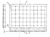
- Fig. 2 is a carrier plate according to another embodiment shown in plan view.
- the support plate 2 shown here has holes in a square grid, which are used as recesses 11 for the formation of transverse stiffening elements 5.
- the holes can be made using conventional drilling techniques.
- the recesses 11 can also be formed by pressing a heated, tubular element into the carrier layer 2.
- the carrier layer 2 in the Fig. 2 also has a groove 9 which is formed on the side surfaces 8 as a circumferential groove. This means that the groove 9 is formed along the entire circumference of the carrier layer 2.
- Fig. 3 shows a device for forming the transverse stiffening elements 5 in the carrier layer 2 of the Fig. 2 ,
- recesses 11 are already formed in the carrier layer 2.
- a spacer dowel 25 is arranged in each recess 11, a spacer dowel 25 is arranged.
- the recesses are filled with a thermosetting material.
- the carrier layer 2 is arranged on a worktop 23.
- metering elements 30 are brought to the carrier layer 2.
- the in the Fig. 3 illustrated device has 10 metering elements 30 which can fill parallel or simultaneous 10 recesses 11.
- a simpler device may include fewer metering elements 30, but with longer production times.
- transverse stiffening elements 5 and their arrangement in the carrier layer 2 depend crucially on the desired load capacity of the building component 1, the thickness of the carrier layer 2 and other parameters. In cylindrical Querversteifungsungskementen 5, however, these should preferably not fall below a diameter of about 20 mm.
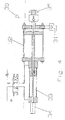
- Fig. 4 shows a metering element 30, which in the device from the Fig. 3 is used.
- the metering element 30 has an inlet 31, through which the hardening material, for example, a potting compound of multi-component resin, is introduced into a Dosicrzylinder 32.
- the hardening material for example, a potting compound of multi-component resin
- the amount of the potting compound which is conveyed through a spray nozzle 35, controlled. This is done with the aid of a linear displacement transducer 34, which measures how far a piston has been moved in the control cylinder 33, which is preferably designed as a hydraulic cylinder.
- the spray nozzle 35 of the metering element 30 is arranged over an opening of the recess 11, so that a metered amount of hardening material is conveyed through the spray nozzle 35 into the recess 11.
- Fig. 5 schematically shows an apparatus for producing a building component 1, which comprises a layer arrangement 24 of a carrier layer 2, a cover layer 3 and a further cover layer 7.
- the apparatus comprises a lower pressing surface 20, an upper pressing surface 21 and side walls 22.
- the layer assembly 24 is disposed between the lower pressing surface 20 and the upper pressing surface 21.
- the lower pressing surface 20, the upper pressing surface 21 and the side walls 22 form a working space 26, in which the layer arrangement 24 is arranged and which is sealed off from the environment in a vacuum-tight manner.
- a vacuum is generated in the working space 26.
- At least one of the pressing surfaces 20, 21 is heated during the pressing to assist the laminating process.
- both the lower pressing surface 20 and the upper pressing surface 21 are heated.
- the pressing surfaces 20, 21 preferably have a width of about 500 to 3000 mm and a length of about 5000 to 30,000 mm.
- the lower pressing surface 20 and / or the upper pressing surface 21 are preferably produced plane-parallel from anodized aluminum sheets.
- the side walls 22 are along all four side surfaces 8 of the carrier layer 2 and preferably each about 100 to 300 mm high. They are preferably made of a smooth anodized sheet.
- the manufacture of the building component 1 takes place as follows.
- impregnating layer 3 for example, a glass resin mat impregnated with casting resin, placed.
- the impregnated cover layer is rolled by means of a rolling roller to rid it of pores, wrinkles and air bubbles.
- the carrier layer 2 which preferably has a thickness of about 10 to 400 mm, arranged.
- the carrier layer 2 is also rolled out in order to guarantee a pore-free bonding between the cover layer 3 and the carrier layer 2.
- the further covering layer 7 is applied to the carrier layer 2.
- the further cover layer 7 is also rolled over by means of the roller in order to obtain a smooth and non-porous surface.
- the upper pressing surface 21 is now arranged and sealed, for example by means of sealing strips arranged on the face side (not shown), in a vacuum-tight manner.
- a vacuum pump By means of a vacuum pump, a vacuum with approximately 20 to 40% vacuum pressure is generated in the working space 26 thus formed, so that the pressing surfaces 20, 21 are pressed onto the layer arrangement 24 from two sides.
- a constant heating and curing of the impregnating agent is thus achieved.
- the transverse stiffening elements 5 extending over the entire thickness of the carrier layer 2, which have a cylindrical shape in the embodiment shown here, touch both cover layers 3, 7. Therefore, when the layer arrangement 24 is pressed, a firm connection is also created between the transverse stiffening elements 5 and the cover layers 3 , 7.
- a negative pressure generated by the vacuum in cavities of the carrier layer 2 also results in that the impregnation agent of the cover layer 3, 7 penetrates into the cavities of the carrier layer 2 and thus forms a stronger connection between the layers.
- a release agent is mixed into the impregnation agent in order to ensure a simple release of the building component 1 from the press surfaces 20, 21.
- a sacrificial layer 10 on one side or both sides on the carrier layer 2 or on the cover layers 3, 7 a sacrificial layer 10 likewise by means of in the Fig. 5 formed device by first a mixture of a base material, such as styrene, and a foaming agent, such as pentane, on the support layer 2 or the cover layer 3.7 is applied.
- the device shown allows the foaming agent to be applied, so that the foamed sacrificial layer 10 is formed from the base material.
- the foam-like cake produced due to the flare has air bubbles with a diameter of the order of about 0.5 to 3 mm.
- the upper pressing surface 21 is adjusted to a desired height above the lower pressing surface 20 and fixed. In order to achieve a short inflation and curing time, in this case the mixture of base material and foaming agent by means of the upper pressing surface 21 is heated to above 100 ° C.
- the sacrificial layer 10 produced in this way unfolds its effect independently of the transverse stiffening elements 5 in the carrier layer 2.
- the sacrificial layer 10 comprises a carrier material with a porous material grid.
- the carrier material is formed, for example, from glass wool fibers, which are pressed into a glass fiber mat and can have any desired thickness.
- the carrier material is impregnated with a resin / hardener mixture, to which additionally a fire-retardant filler is added.
- the mixing ratio of the resin / hardener / filler mixture is adjusted so that a self-extinguishing and non-combustible material results.
- the mixing ratio is about 100: 30: 60 to 100: 30: 80.
- the proportion of filler is thus higher than in the case of other cast resin laminates, for example in the case of the laminated cover layers 3, 7, which, for example, consist of a resin / hardener / filler mixture with a mixing ratio of 100: 30: 25 to 100: 30: 40 may be formed.
- the recesses 11 for the transverse stiffening elements 5 can also be filled with such a resin / hardener / filler mixture by means of the metering elements 30 described above.
- Such fire-retardant fillers which are usually in powder form, comprise a high proportion of water of crystallization and therefore extinguish fires. In the case of a fire, the water of crystallization evaporates, removing heat from the flames so that they go out.
- the powdered filler is preferably admixed in quantities of 60 to 40% by mass ratio to the impregnating agent for the sacrificial layer.
- Filler can be used, for example, commercially available hexabromocyclododecane (HBCD), a brominated cycloaliphatic hydrocarbon.
- a further layer for example a finely structured woven mat, may preferably be applied to improve the appearance and / or feel
- Fig. 6 shows an embodiment in which the carrier layer 2 comprises a split core of a foamed material.
- the core comprises two partial cores 2 a and 2 b, which are connected to one another by means of spacers 27.
- the spacers ensure that the split cores 2 a and 2 b maintain a constant distance from each other.
- the split core may comprise a larger number of sub-cores of the same or different dimensions and with the same or different spacing between the sub-cores.
- a cavity is formed, which is filled with air.
- the cavity between the sub-cores 2a and 2b may be filled in other embodiments with a different gas or with another material, for example, to favor the thermal insulation.
- Spacers 27 are formed as spacers and form part of the transverse stiffening elements 5. They are cylindrically shaped and have at their end faces on annular surfaces.
- the recesses 11 formed in the carrier layer 2 extend through the spacers 27 from one sub-core 2a into the other sub-core 2b. In each recess 11, a spacer dowel 25 is arranged, and the recesses 11 are filled with the cured material.
Landscapes
- Engineering & Computer Science (AREA)
- Architecture (AREA)
- Civil Engineering (AREA)
- Structural Engineering (AREA)
- Laminated Bodies (AREA)
- Finishing Walls (AREA)
Applications Claiming Priority (1)
| Application Number | Priority Date | Filing Date | Title |
|---|---|---|---|
| DE102007030339A DE102007030339A1 (de) | 2007-06-29 | 2007-06-29 | Gebäudebauelement und Verfahren zum Herstellen |
Publications (2)
| Publication Number | Publication Date |
|---|---|
| EP2009190A2 true EP2009190A2 (fr) | 2008-12-31 |
| EP2009190A3 EP2009190A3 (fr) | 2010-04-28 |
Family
ID=39768770
Family Applications (1)
| Application Number | Title | Priority Date | Filing Date |
|---|---|---|---|
| EP08011683A Withdrawn EP2009190A3 (fr) | 2007-06-29 | 2008-06-27 | Elément de bâtiment et procédé de fabrication |
Country Status (2)
| Country | Link |
|---|---|
| EP (1) | EP2009190A3 (fr) |
| DE (1) | DE102007030339A1 (fr) |
Cited By (3)
| Publication number | Priority date | Publication date | Assignee | Title |
|---|---|---|---|---|
| GB2456659A (en) * | 2008-01-22 | 2009-07-29 | Matthew Smyth | High structural strength sandwich panel |
| US9604442B2 (en) | 2008-11-24 | 2017-03-28 | Applied Ft Composite Solutions Inc. | Peeling process for making resilient pad composite |
| US11890843B2 (en) | 2010-11-24 | 2024-02-06 | Applied Ft Composite Solutions Inc. | Composite cushioning material and jigless method for making the same |
Family Cites Families (12)
| Publication number | Priority date | Publication date | Assignee | Title |
|---|---|---|---|---|
| AT232695B (de) * | 1961-02-13 | 1964-03-25 | Emil Dipl Ing Grohmann | Mehrschichten-Bauplatte |
| DE1867587U (de) * | 1962-12-15 | 1963-02-21 | Eduard Dyckerhoff G M B H | Verbundplatte. |
| DE1704872A1 (de) * | 1967-11-22 | 1971-05-27 | Graaff J Niedersaechs Waggon | Verfahren zur Herstellung einer Mehrschichtenplatte |
| DE2241886A1 (de) * | 1972-08-25 | 1974-03-07 | Hebel Gasbetonwerk Gmbh | Grossformatige verbundwandplatte |
| DE7541258U (de) * | 1975-12-24 | 1976-06-03 | Gut, Max, 7713 Huefingen | Bauplatte |
| DE3005015A1 (de) * | 1980-02-11 | 1981-08-20 | Olbrich, Kurt, 6120 Erbach | Baukoerper in sandwichbauweise mit verstegtem hartschaumkern und verfahren zu seiner herstellung |
| DE9110061U1 (de) * | 1990-11-20 | 1992-04-16 | R.M.T. Glider Manufacturers cc, Mandini | Schichtstoff mit einer Kernschicht aus geschäumtem Kunststoff |
| DE4301565A1 (de) * | 1993-01-21 | 1994-07-28 | Bernd Baar | Bauwerk-Leichtbauelement |
| DE69434917T2 (de) * | 1993-05-04 | 2007-11-08 | Foster-Miller, Inc., Waltham | Gittergestützte verbundplatte mit schaumkern |
| DE19818829A1 (de) * | 1998-04-27 | 1999-11-11 | D.D.C. Planungs-, Entwicklungs- Und Management Ag | Schalldämmendes Wandelement |
| US6291049B1 (en) * | 1998-10-20 | 2001-09-18 | Aztex, Inc. | Sandwich structure and method of making same |
| ITMI20050119A1 (it) * | 2005-01-28 | 2006-07-29 | Top Glass Spa | Struttura di pannello e relativo procedimento di realizzazione |
-
2007
- 2007-06-29 DE DE102007030339A patent/DE102007030339A1/de not_active Ceased
-
2008
- 2008-06-27 EP EP08011683A patent/EP2009190A3/fr not_active Withdrawn
Cited By (3)
| Publication number | Priority date | Publication date | Assignee | Title |
|---|---|---|---|---|
| GB2456659A (en) * | 2008-01-22 | 2009-07-29 | Matthew Smyth | High structural strength sandwich panel |
| US9604442B2 (en) | 2008-11-24 | 2017-03-28 | Applied Ft Composite Solutions Inc. | Peeling process for making resilient pad composite |
| US11890843B2 (en) | 2010-11-24 | 2024-02-06 | Applied Ft Composite Solutions Inc. | Composite cushioning material and jigless method for making the same |
Also Published As
| Publication number | Publication date |
|---|---|
| DE102007030339A1 (de) | 2009-01-02 |
| EP2009190A3 (fr) | 2010-04-28 |
Similar Documents
| Publication | Publication Date | Title |
|---|---|---|
| AT406064B (de) | Bauelement | |
| DE10341255B4 (de) | Wärmeleitplatten aus expandiertem Graphit sowie Verfahren zu ihrer Herstellung | |
| EP0611406B1 (fr) | Materiau isolant sous forme de panneau ou de bande pour ouvrages neufs ou necessitant une renovation | |
| DE3234903A1 (de) | Kompositbaumaterialien mit verbesserter feuerbestaendigkeit und verfahren zur herstellung | |
| EP2257506B1 (fr) | Procédé de fabrication d'un élément de construction en forme de plaque ou de profilé et élément de construction en forme de plaque ou de profilé | |
| DE102007030339A1 (de) | Gebäudebauelement und Verfahren zum Herstellen | |
| DE3603069C2 (fr) | ||
| DE102004018550B4 (de) | Polyethylenschäume mit geringer dynamischer Steifigkeit | |
| DE2927425A1 (de) | Waermegedaemmter fertigbauteil zum herstellen von boeden | |
| DE2320170A1 (de) | Verfahren zur herstellung von gegenstaenden aus waermehaertenden harzen | |
| DE2324915A1 (de) | Bauelement | |
| WO2011060468A1 (fr) | Elément composite et brique en bois | |
| AT509157B1 (de) | Verbundelement | |
| EP1305159A2 (fr) | Elements de construction legers et leur procede de production | |
| EP2739800A1 (fr) | Élément multicouche | |
| EP0191892B1 (fr) | Objets formés contenant un noyau de support et procédé pour leur fabrication | |
| DE19502378A1 (de) | Akustikplatte | |
| DE4100796C2 (de) | Leichtbauelement | |
| AT526217B1 (de) | Trägerartiges, aus Einzelteilen zusammengeschweißtes Bauelement | |
| DE2119863A1 (en) | Lightweight building panel prodn - with deformed reinforcing core | |
| EP0621123B1 (fr) | Système de chauffage sous sol | |
| DE1609889C (de) | Großflächiges Bauelement aus Schicht Verbundplatten und Verfahren zu seiner Her stellung | |
| DE102017129383A1 (de) | Verfahren zur Herstellung eines mehrschichtigen Fertigbauelements | |
| DE2117166A1 (de) | Vorgefertigte bauplatten und verfahren zum herstellen derselben | |
| DE19818829A1 (de) | Schalldämmendes Wandelement |
Legal Events
| Date | Code | Title | Description |
|---|---|---|---|
| PUAI | Public reference made under article 153(3) epc to a published international application that has entered the european phase |
Free format text: ORIGINAL CODE: 0009012 |
|
| AK | Designated contracting states |
Kind code of ref document: A2 Designated state(s): AT BE BG CH CY CZ DE DK EE ES FI FR GB GR HR HU IE IS IT LI LT LU LV MC MT NL NO PL PT RO SE SI SK TR |
|
| AX | Request for extension of the european patent |
Extension state: AL BA MK RS |
|
| PUAL | Search report despatched |
Free format text: ORIGINAL CODE: 0009013 |
|
| AK | Designated contracting states |
Kind code of ref document: A3 Designated state(s): AT BE BG CH CY CZ DE DK EE ES FI FR GB GR HR HU IE IS IT LI LT LU LV MC MT NL NO PL PT RO SE SI SK TR |
|
| AX | Request for extension of the european patent |
Extension state: AL BA MK RS |
|
| 17P | Request for examination filed |
Effective date: 20101026 |
|
| 17Q | First examination report despatched |
Effective date: 20101126 |
|
| AKY | No designation fees paid | ||
| STAA | Information on the status of an ep patent application or granted ep patent |
Free format text: STATUS: THE APPLICATION IS DEEMED TO BE WITHDRAWN |
|
| 18D | Application deemed to be withdrawn |
Effective date: 20110104 |