EP2009196A1 - Improved tile for forming floors - Google Patents
Improved tile for forming floors Download PDFInfo
- Publication number
- EP2009196A1 EP2009196A1 EP07730438A EP07730438A EP2009196A1 EP 2009196 A1 EP2009196 A1 EP 2009196A1 EP 07730438 A EP07730438 A EP 07730438A EP 07730438 A EP07730438 A EP 07730438A EP 2009196 A1 EP2009196 A1 EP 2009196A1
- Authority
- EP
- European Patent Office
- Prior art keywords
- panel
- fitting
- connection
- portions
- grooves
- Prior art date
- Legal status (The legal status is an assumption and is not a legal conclusion. Google has not performed a legal analysis and makes no representation as to the accuracy of the status listed.)
- Withdrawn
Links
Images

Classifications
-
- E—FIXED CONSTRUCTIONS
- E04—BUILDING
- E04F—FINISHING WORK ON BUILDINGS, e.g. STAIRS, FLOORS
- E04F15/00—Flooring
- E04F15/02—Flooring or floor layers composed of a number of similar elements
- E04F15/022—Flooring consisting of parquetry tiles on a non-rollable sub-layer of other material, e.g. board, concrete, cork
-
- E—FIXED CONSTRUCTIONS
- E04—BUILDING
- E04F—FINISHING WORK ON BUILDINGS, e.g. STAIRS, FLOORS
- E04F15/00—Flooring
- E04F15/02—Flooring or floor layers composed of a number of similar elements
- E04F15/02194—Flooring consisting of a number of elements carried by a non-rollable common support plate or grid
-
- E—FIXED CONSTRUCTIONS
- E04—BUILDING
- E04F—FINISHING WORK ON BUILDINGS, e.g. STAIRS, FLOORS
- E04F15/00—Flooring
- E04F15/02—Flooring or floor layers composed of a number of similar elements
- E04F15/04—Flooring or floor layers composed of a number of similar elements only of wood or with a top layer of wood, e.g. with wooden or metal connecting members
- E04F15/041—Flooring or floor layers composed of a number of similar elements only of wood or with a top layer of wood, e.g. with wooden or metal connecting members with a top layer of wood in combination with a lower layer of other material
- E04F15/043—Flooring or floor layers composed of a number of similar elements only of wood or with a top layer of wood, e.g. with wooden or metal connecting members with a top layer of wood in combination with a lower layer of other material the lower layer being of organic plastic with or without reinforcements or filling materials
-
- E—FIXED CONSTRUCTIONS
- E04—BUILDING
- E04F—FINISHING WORK ON BUILDINGS, e.g. STAIRS, FLOORS
- E04F15/00—Flooring
- E04F15/02—Flooring or floor layers composed of a number of similar elements
- E04F15/10—Flooring or floor layers composed of a number of similar elements of other materials, e.g. fibrous or chipped materials, organic plastics, magnesite tiles, hardboard, or with a top layer of other materials
- E04F15/105—Flooring or floor layers composed of a number of similar elements of other materials, e.g. fibrous or chipped materials, organic plastics, magnesite tiles, hardboard, or with a top layer of other materials of organic plastics with or without reinforcements or filling materials
Definitions
- the invention refers to an improved panel for flooring that brings significant innovations and advantages compared to other panels with the same purpose.
- an improved panel for flooring that has a laminar body with a generally rectangular or square shape that has means of connection and fitting together made by sections of tongues and grooves on at least one of the outer sides of the laminar body so as to fit into another similar or equal panel with complementary means of connection and fitting together.
- Rectangular panels are widely known that can be connected to each other for the formation of floating floors in internal or external areas such as swimming pools, terraces, etc., which have means for their connection and fitting together, such as, for example, a linking system of tongues and grooves on the outer edges of the panel so as to fit into complementary panels by any of the four sides.
- the present invention has been developed for the purpose of providing an improved panel aimed at solving the previously stated disadvantages, in addition bringing other advantages that will be evident from the description that is attached below.
- the improved panel of the invention is intended for the arrangement of floors known as floating floors, being of the type that is made up of an essentially laminar body with a rectangular or square shape that has means of connection and fitting together made of sections of tongues and grooves on at least one side of the laminar body so as to fit to another panel that has the same or similar shape by some complementary means for connecting and fitting together to cover the floor, and characterised in that in addition it has means of separation so as to form at least two independent panel portions, each one of the portions having been provided with means of connection and fitting together for fixing and connecting with the connection and fitting means placed on the outer side of the panel.
- the separation means are made up with a plurality of grooves for cutting arranged in one or more directions that partially or completely cross the panel.
- a panel is obtained of the previous type that can be divided in a simple and quick manner into various portions with differing dimensions, making it very useful for the final sections or corners during the fitting of floating floors where normally the last panel to be fitted is smaller than the size of the panel, and in turn retaining the same type of internal fixing as the outer areas of the panel hence making the assembly almost immediate.
- the connecting and fitting means of the portions have grooves placed along the grooves for cutting on one or both sides of said grooves for cutting.
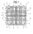
- Figure 1 shows an embodiment of an improved panel for flooring that includes a laminar body (1) of an injection mouldable plastic material with a square shape, having means of connection and fitting made by tongues (2) and grooves sections (3) on the four sides of the laminar body (1) in order to fit it to another panel that is the same or similar with complementary connection and fitting means so as to cover the floor, in addition having means of separation so as to form at least two independent portions of the panel, each one of the portions being provided with means of connection and fitting so as to connect and fit to a panel.
- a laminar body (1) of an injection mouldable plastic material with a square shape having means of connection and fitting made by tongues (2) and grooves sections (3) on the four sides of the laminar body (1) in order to fit it to another panel that is the same or similar with complementary connection and fitting means so as to cover the floor, in addition having means of separation so as to form at least two independent portions of the panel, each one of the portions being provided with means of connection and fitting so as to connect and fit to a panel.
- the means of separation consist of a plurality of grooves for cutting (4) arranged in one or more directions, this means, diagonally or perpendicularly to them, that partially or completely cross the laminar body (1).
- grooves (5) located along the various grooves for cutting (4) on one or both sides of each groove for cutting as in a system of tongues and grooves.
- the laminar body can be divided, for example, into four equal quadrangles (10) (shown by broken lines) or multiple rectangular portions and at the same time, each portion (10) can be sub-divided into other rectangular portions.
- Figure 2 shows one of the portions (10) cut whilst in figure 3 a rectangular cut portion of the portion (10) can be seen, in this way showing that a variety of arrangements can be made by means of a simple cut that the panel of the invention allows.
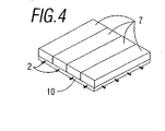
- the panel has been thought out basically for receiving on top, for example, some wooden strips (7). Due to the structure of the panel described there is also the possibility of modifying the direction of the wooden strips (7), in order to make the re-installation of the wooden strips easier and in a quick and simple manner and thus allowing the cutting of the panel in a new direction if so required, being able to assemble the floor with wooden strips (7) in two perpendicular directions. On the other hand, as can be seen from upper left part on the inside of the laminar body (1) of figure 1 there are some changeable protrusions or tongues (6) that can be used in the event of breakage of any of the protruding tongues (2) or to make pre-determined designs and finishes easier.
Landscapes
- Engineering & Computer Science (AREA)
- Architecture (AREA)
- Civil Engineering (AREA)
- Structural Engineering (AREA)
- Life Sciences & Earth Sciences (AREA)
- Wood Science & Technology (AREA)
- Floor Finish (AREA)
Abstract
Description
- The invention refers to an improved panel for flooring that brings significant innovations and advantages compared to other panels with the same purpose.
- More specifically it relates to an improved panel for flooring that has a laminar body with a generally rectangular or square shape that has means of connection and fitting together made by sections of tongues and grooves on at least one of the outer sides of the laminar body so as to fit into another similar or equal panel with complementary means of connection and fitting together.
- Rectangular panels are widely known that can be connected to each other for the formation of floating floors in internal or external areas such as swimming pools, terraces, etc., which have means for their connection and fitting together, such as, for example, a linking system of tongues and grooves on the outer edges of the panel so as to fit into complementary panels by any of the four sides.
- However, during the fitting of floating floors by means of these panels, it is usual in the final stage of fitting that the last part to be covered with the floating floor has some dimensions that are smaller than the size of the panel, hence the fitter must cut the panel in the best way possible, on the majority of the occasions this producing an irregular shaped cut.
- The present invention has been developed for the purpose of providing an improved panel aimed at solving the previously stated disadvantages, in addition bringing other advantages that will be evident from the description that is attached below.
- The improved panel of the invention is intended for the arrangement of floors known as floating floors, being of the type that is made up of an essentially laminar body with a rectangular or square shape that has means of connection and fitting together made of sections of tongues and grooves on at least one side of the laminar body so as to fit to another panel that has the same or similar shape by some complementary means for connecting and fitting together to cover the floor, and characterised in that in addition it has means of separation so as to form at least two independent panel portions, each one of the portions having been provided with means of connection and fitting together for fixing and connecting with the connection and fitting means placed on the outer side of the panel.
- By preference, the separation means are made up with a plurality of grooves for cutting arranged in one or more directions that partially or completely cross the panel.
- Thanks to these characteristics, a panel is obtained of the previous type that can be divided in a simple and quick manner into various portions with differing dimensions, making it very useful for the final sections or corners during the fitting of floating floors where normally the last panel to be fitted is smaller than the size of the panel, and in turn retaining the same type of internal fixing as the outer areas of the panel hence making the assembly almost immediate.
- Also, preferently, the connecting and fitting means of the portions have grooves placed along the grooves for cutting on one or both sides of said grooves for cutting.
- Other characteristics and advantages of the improved panel object of this present invention will become clear from a description of a preferred embodiment, but it is not exclusive, the drawings that are attached are by way of illustration but without being in any way limiting.
-
-
Figure 1 . - It is a plan view of an improved panel for flooring according to the invention; -
Figure 2 . - It is a plan view of a quadrangular portion of a panel of the invention appearing in the previous figure; -
Figure 3 . - It is a plan view of a rectangular portion of a panel of the invention; and -
Figure 4 . - It is a perspective view corresponding to an improved panel with strips attached above. -
Figure 1 shows an embodiment of an improved panel for flooring that includes a laminar body (1) of an injection mouldable plastic material with a square shape, having means of connection and fitting made by tongues (2) and grooves sections (3) on the four sides of the laminar body (1) in order to fit it to another panel that is the same or similar with complementary connection and fitting means so as to cover the floor, in addition having means of separation so as to form at least two independent portions of the panel, each one of the portions being provided with means of connection and fitting so as to connect and fit to a panel. - The means of separation consist of a plurality of grooves for cutting (4) arranged in one or more directions, this means, diagonally or perpendicularly to them, that partially or completely cross the laminar body (1).
- In regard to the connecting and fitting means of the portions there are grooves (5) located along the various grooves for cutting (4) on one or both sides of each groove for cutting as in a system of tongues and grooves.
- As can be seen in the attached figure, the laminar body can be divided, for example, into four equal quadrangles (10) (shown by broken lines) or multiple rectangular portions and at the same time, each portion (10) can be sub-divided into other rectangular portions.
Figure 2 shows one of the portions (10) cut whilst infigure 3 a rectangular cut portion of the portion (10) can be seen, in this way showing that a variety of arrangements can be made by means of a simple cut that the panel of the invention allows. - The panel has been thought out basically for receiving on top, for example, some wooden strips (7). Due to the structure of the panel described there is also the possibility of modifying the direction of the wooden strips (7), in order to make the re-installation of the wooden strips easier and in a quick and simple manner and thus allowing the cutting of the panel in a new direction if so required, being able to assemble the floor with wooden strips (7) in two perpendicular directions. On the other hand, as can be seen from upper left part on the inside of the laminar body (1) of
figure 1 there are some changeable protrusions or tongues (6) that can be used in the event of breakage of any of the protruding tongues (2) or to make pre-determined designs and finishes easier. - The details, shapes, sizes and other accessorial elements, likewise the materials used in the manufacture of the improved panel of the invention can be appropriately substituted by others that are technically equivalent and do not stray away from the essentiality of the invention or the scope defined by the claims that are included below.
Claims (3)
- Improved panel (1) for flooring, comprising a laminar body with a rectangular or square shape that has means of connection and fitting made of tongues (2) and grooves (3) on at least one side of the laminar body so as to fit to another panel that is the same or similar, having complementary means of connection and fitting to cover the floor, characterised in that in addition it has means of cutting so as to form at least two independent panel portions (10), each one of the portions having been provided with means of connection and fitting for connecting and coupling with the connection and fitting means on the outer side of a panel (1).
- Improved panel (1) according to Claim 1, characterised in that the means of separation consist of a plurality of grooves for cutting (4) arranged in one or more directions that partially or completely cross the panel.
- Improved panel (1) according to Claims 1 and 2 characterised in that the means for connection and fitting of the portions are grooves along the grooves for cutting(4) on one or both sides of each groove for cutting.
Applications Claiming Priority (2)
| Application Number | Priority Date | Filing Date | Title |
|---|---|---|---|
| ES200600868U ES1062734Y (en) | 2006-04-17 | 2006-04-17 | PERFECTED PLATE FOR SOIL CONFIGURATION |
| PCT/ES2007/000198 WO2007118913A1 (en) | 2006-04-17 | 2007-04-10 | Improved tile for forming floors |
Publications (2)
| Publication Number | Publication Date |
|---|---|
| EP2009196A1 true EP2009196A1 (en) | 2008-12-31 |
| EP2009196A4 EP2009196A4 (en) | 2011-11-23 |
Family
ID=36676799
Family Applications (1)
| Application Number | Title | Priority Date | Filing Date |
|---|---|---|---|
| EP07730438A Withdrawn EP2009196A4 (en) | 2006-04-17 | 2007-04-10 | Improved tile for forming floors |
Country Status (5)
| Country | Link |
|---|---|
| US (1) | US20100043334A1 (en) |
| EP (1) | EP2009196A4 (en) |
| ES (1) | ES1062734Y (en) |
| MX (1) | MX2008013091A (en) |
| WO (1) | WO2007118913A1 (en) |
Families Citing this family (6)
| Publication number | Priority date | Publication date | Assignee | Title |
|---|---|---|---|---|
| US9016625B2 (en) * | 2011-05-11 | 2015-04-28 | The Boeing Company | Reconfigurable floorboard system |
| US11813425B2 (en) | 2011-12-29 | 2023-11-14 | Medline Industries, Lp | Apparatus pertaining to a base for a vertical support pole |
| US9737654B2 (en) * | 2011-12-29 | 2017-08-22 | Medline Industries, Inc. | Intravenous pole base having tessellating elements |
| JP5972001B2 (en) * | 2012-03-26 | 2016-08-17 | 積水化学工業株式会社 | Polygon-shaped floor decorative board and connecting method of polygon-shaped decorative floor board |
| USD902445S1 (en) * | 2018-02-22 | 2020-11-17 | Samwon Act Co., Ltd. | Connection bracket of building interior material |
| KR102074769B1 (en) * | 2018-02-22 | 2020-02-07 | 삼원액트 주식회사 | The metal interior material and interior material attachment structure |
Family Cites Families (34)
| Publication number | Priority date | Publication date | Assignee | Title |
|---|---|---|---|---|
| DE2221761C3 (en) * | 1972-05-04 | 1980-04-03 | Rhofa Sportbodenbau Gmbh, 4803 Steinhagen | Sprung floor |
| US4054987A (en) * | 1976-02-26 | 1977-10-25 | Mateflex/Mele Corporation | Construction method |
| NL7701096A (en) * | 1977-02-02 | 1978-08-04 | Kraayenhof Design B V Vlosberg | FLOOR COVERING, COMPOSED OF CONNECTING PLASTIC ELEMENTS. |
| US4436779A (en) * | 1982-07-02 | 1984-03-13 | Menconi K Anthony | Modular surface such as for use in sports |
| US4749302A (en) * | 1983-05-16 | 1988-06-07 | Declute Robert G | Spacing pad |
| US4584221A (en) * | 1984-07-19 | 1986-04-22 | Sportforderung Peter Kung Ag | Floor covering assembly |
| DK155616C (en) * | 1984-09-25 | 1989-09-04 | Eminent Plast | GRID OR MEASUREMENT ELEMENT FOR THE CREATION OF A FLOOR COVERING BY CONNECTION WITH SIMILAR ELEMENTS |
| ATE84587T1 (en) * | 1986-10-22 | 1993-01-15 | Cablescape Access Flooring Pty | MODULAR HOLLOW FLOOR PANELS WITH INTEGRATED CABLE ROUTING. |
| US4860510A (en) * | 1988-03-14 | 1989-08-29 | Duragrid, Inc. | Modular protective surfacing member |
| US4930286A (en) * | 1988-03-14 | 1990-06-05 | Daniel Kotler | Modular sports tile with lateral absorption |
| EP0488312B1 (en) * | 1990-11-29 | 1995-01-18 | Kabushiki Kaisha Toshiba | Method for manufacturing system floor and floor base for system floor |
| US5190799A (en) * | 1991-05-09 | 1993-03-02 | Reese Enterprises, Inc. | Floor covering with integral walking surface |
| DK89291D0 (en) * | 1991-05-13 | 1991-05-13 | Frank Bentzon | FLOORING SYSTEM WITH LINKABLE TILE ELEMENTS, NAMELY PLASTIC TILES |
| USD347722S (en) * | 1992-09-11 | 1994-06-07 | Rehrig Pacific Company, Inc. | Tray floor construction |
| AU651053B3 (en) * | 1993-10-22 | 1994-07-07 | Otto Wu | Foot sole massage device |
| JPH0941641A (en) * | 1995-08-01 | 1997-02-10 | Kenjiro Teramoto | Mat made of synthetic resin |
| IT240768Y1 (en) * | 1996-07-04 | 2001-04-11 | Cincla Srl | MODULAR ELEMENT FOR MODULAR ELASTIC MATERIAL FLOORS |
| US5761867A (en) * | 1996-10-11 | 1998-06-09 | Sport Court, Inc. | Tile support insert |
| US6032428A (en) * | 1997-10-27 | 2000-03-07 | Ameritech Plastics Incorporated (A Delaware Corporation) | Modular roll-out portable floor for ice surfaces |
| US5950378A (en) * | 1997-12-22 | 1999-09-14 | Council; Walter S. | Composite modular floor tile |
| AUPP137798A0 (en) * | 1998-01-16 | 1998-02-05 | Ezydeck Pty Ltd | Decking tile |
| US6694689B1 (en) * | 1998-02-13 | 2004-02-24 | Interface, Inc. | Modular flooring systems and methods |
| US6098354A (en) * | 1998-04-07 | 2000-08-08 | Dante Design Associates, Inc. | Modular floor tile having reinforced interlocking portions |
| CA2435460A1 (en) * | 2001-01-29 | 2002-08-08 | Spider Court, Inc. | Modular tile and tile flooring system |
| US6684592B2 (en) * | 2001-08-13 | 2004-02-03 | Ron Martin | Interlocking floor panels |
| ATE322592T1 (en) * | 2001-10-18 | 2006-04-15 | Bresciana Graniti S P A | COMPOSITE BOARD FOR FALLED FLOORS |
| EP1490565B1 (en) * | 2001-11-28 | 2007-09-26 | Meyer, Hans | Laying system for floor tiles |
| US6802159B1 (en) * | 2002-05-31 | 2004-10-12 | Snap Lock Industries, Inc. | Roll-up floor tile system and the method |
| WO2005081923A2 (en) * | 2004-02-20 | 2005-09-09 | Tennessee Mat Company, Inc | Interlocking modular floor tile |
| US7462253B2 (en) * | 2004-03-29 | 2008-12-09 | Nevison Dale C H | Process for bonding grit into mat trenches |
| JP4376713B2 (en) * | 2004-07-12 | 2009-12-02 | 積水化学工業株式会社 | Floor member, connecting member and laying structure of the floor member |
| DE202005013553U1 (en) * | 2005-07-29 | 2006-09-07 | Fickler, Verena | Underlay for flooring element, has supporting members distributed on underlay lower surface |
| US7543417B2 (en) * | 2005-10-04 | 2009-06-09 | Comc, Llc | Modular flooring assemblies |
| US20080173569A1 (en) * | 2007-01-23 | 2008-07-24 | Illinois Tool Works Inc. | Pedestal pocket tray containment system for integrated circuit chips |
-
2006
- 2006-04-17 ES ES200600868U patent/ES1062734Y/en not_active Expired - Fee Related
-
2007
- 2007-04-10 MX MX2008013091A patent/MX2008013091A/en unknown
- 2007-04-10 US US12/297,243 patent/US20100043334A1/en not_active Abandoned
- 2007-04-10 WO PCT/ES2007/000198 patent/WO2007118913A1/en not_active Ceased
- 2007-04-10 EP EP07730438A patent/EP2009196A4/en not_active Withdrawn
Also Published As
| Publication number | Publication date |
|---|---|
| ES1062734U (en) | 2006-07-16 |
| US20100043334A1 (en) | 2010-02-25 |
| WO2007118913A1 (en) | 2007-10-25 |
| MX2008013091A (en) | 2008-10-21 |
| ES1062734Y (en) | 2006-10-16 |
| EP2009196A4 (en) | 2011-11-23 |
Similar Documents
| Publication | Publication Date | Title |
|---|---|---|
| US12366071B2 (en) | Panel | |
| EP2009196A1 (en) | Improved tile for forming floors | |
| US10132069B2 (en) | Plastic infiltration unit, a system comprising a plurality of plastic infiltration units | |
| US12326001B2 (en) | Panel with locking device | |
| US4090338A (en) | Parquet floor elements and parquet floor composed of such elements | |
| US6446413B1 (en) | Portable graphic floor system | |
| WO2015200786A4 (en) | Interlocking mat with integral ramp and a method of use | |
| CN104379852B (en) | Floating floor system, floor panels and method of installation thereof | |
| US7540684B1 (en) | Interlocking rubber mat resembling a paving stone surface | |
| US20080295440A1 (en) | Building component | |
| EP2492416A1 (en) | System for floor covering | |
| US20160177576A1 (en) | Interlocking floor panels and floor system | |
| USD880012S1 (en) | Modular flooring tile with cable channels | |
| ES2548416T3 (en) | Furniture frame | |
| JP2007507628A (en) | Structural panel | |
| US20070022689A1 (en) | Plastic flooring with improved seal | |
| US20160002913A1 (en) | Building element composed of two panels with a coupling strip | |
| US20170280908A1 (en) | Floor mat | |
| GB2555406A (en) | An architectural structure | |
| US20130122234A1 (en) | Precast veneer panel arrangement | |
| CN114008280B (en) | Panel and covering comprising a panel | |
| JP5796224B2 (en) | Parting connection | |
| JP5898932B2 (en) | Double floor panel structure | |
| JP2007169994A (en) | Deck tile, laying member for use in deck tile, deck tile connection method, and floor structure formed of plurality of deck tiles | |
| JP2011162968A (en) | Judo tatami mat |
Legal Events
| Date | Code | Title | Description |
|---|---|---|---|
| PUAI | Public reference made under article 153(3) epc to a published international application that has entered the european phase |
Free format text: ORIGINAL CODE: 0009012 |
|
| 17P | Request for examination filed |
Effective date: 20081015 |
|
| AK | Designated contracting states |
Kind code of ref document: A1 Designated state(s): AT BE BG CH CY CZ DE DK EE ES FI FR GB GR HU IE IS IT LI LT LU LV MC MT NL PL PT RO SE SI SK TR |
|
| AX | Request for extension of the european patent |
Extension state: AL BA HR MK RS |
|
| A4 | Supplementary search report drawn up and despatched |
Effective date: 20111026 |
|
| RIC1 | Information provided on ipc code assigned before grant |
Ipc: E04F 15/022 20060101AFI20111020BHEP |
|
| DAX | Request for extension of the european patent (deleted) | ||
| STAA | Information on the status of an ep patent application or granted ep patent |
Free format text: STATUS: THE APPLICATION IS DEEMED TO BE WITHDRAWN |
|
| 18D | Application deemed to be withdrawn |
Effective date: 20120525 |