EP2009225B1 - Procédé pour fournir une structure souterraine en forme de dalle - Google Patents
Procédé pour fournir une structure souterraine en forme de dalle Download PDFInfo
- Publication number
- EP2009225B1 EP2009225B1 EP08075578A EP08075578A EP2009225B1 EP 2009225 B1 EP2009225 B1 EP 2009225B1 EP 08075578 A EP08075578 A EP 08075578A EP 08075578 A EP08075578 A EP 08075578A EP 2009225 B1 EP2009225 B1 EP 2009225B1
- Authority
- EP
- European Patent Office
- Prior art keywords
- bore hole
- bore
- injected
- ground
- injection head
- Prior art date
- Legal status (The legal status is an assumption and is not a legal conclusion. Google has not performed a legal analysis and makes no representation as to the accuracy of the status listed.)
- Not-in-force
Links
- 238000000034 method Methods 0.000 title claims description 60
- 238000002347 injection Methods 0.000 claims abstract description 62
- 239000007924 injection Substances 0.000 claims abstract description 62
- 239000000126 substance Substances 0.000 claims abstract description 49
- 238000005553 drilling Methods 0.000 claims abstract description 17
- 235000019353 potassium silicate Nutrition 0.000 claims description 19
- NTHWMYGWWRZVTN-UHFFFAOYSA-N sodium silicate Chemical compound [Na+].[Na+].[O-][Si]([O-])=O NTHWMYGWWRZVTN-UHFFFAOYSA-N 0.000 claims description 19
- 229910000278 bentonite Inorganic materials 0.000 claims description 6
- 239000000440 bentonite Substances 0.000 claims description 6
- SVPXDRXYRYOSEX-UHFFFAOYSA-N bentoquatam Chemical compound O.O=[Si]=O.O=[Al]O[Al]=O SVPXDRXYRYOSEX-UHFFFAOYSA-N 0.000 claims description 6
- 238000011010 flushing procedure Methods 0.000 claims description 5
- 239000007788 liquid Substances 0.000 claims description 5
- 239000000203 mixture Substances 0.000 claims description 5
- 238000003860 storage Methods 0.000 claims description 4
- 230000003014 reinforcing effect Effects 0.000 claims description 3
- 238000007796 conventional method Methods 0.000 description 9
- XLYOFNOQVPJJNP-UHFFFAOYSA-N water Substances O XLYOFNOQVPJJNP-UHFFFAOYSA-N 0.000 description 8
- 238000006073 displacement reaction Methods 0.000 description 4
- 239000000463 material Substances 0.000 description 4
- 239000004576 sand Substances 0.000 description 3
- 239000002699 waste material Substances 0.000 description 3
- 238000010276 construction Methods 0.000 description 2
- 238000001514 detection method Methods 0.000 description 2
- 230000001627 detrimental effect Effects 0.000 description 2
- 230000000694 effects Effects 0.000 description 2
- 239000011440 grout Substances 0.000 description 2
- 239000004568 cement Substances 0.000 description 1
- 239000003795 chemical substances by application Substances 0.000 description 1
- 239000004927 clay Substances 0.000 description 1
- 238000004590 computer program Methods 0.000 description 1
- 238000010924 continuous production Methods 0.000 description 1
- GUJOJGAPFQRJSV-UHFFFAOYSA-N dialuminum;dioxosilane;oxygen(2-);hydrate Chemical compound O.[O-2].[O-2].[O-2].[Al+3].[Al+3].O=[Si]=O.O=[Si]=O.O=[Si]=O.O=[Si]=O GUJOJGAPFQRJSV-UHFFFAOYSA-N 0.000 description 1
- 238000009826 distribution Methods 0.000 description 1
- 239000003673 groundwater Substances 0.000 description 1
- 230000002401 inhibitory effect Effects 0.000 description 1
- 229910052500 inorganic mineral Inorganic materials 0.000 description 1
- 238000009434 installation Methods 0.000 description 1
- 238000005461 lubrication Methods 0.000 description 1
- 239000002075 main ingredient Substances 0.000 description 1
- 239000011707 mineral Substances 0.000 description 1
- 238000012544 monitoring process Methods 0.000 description 1
- 229910052901 montmorillonite Inorganic materials 0.000 description 1
- 239000004848 polyfunctional curative Substances 0.000 description 1
- 230000002787 reinforcement Effects 0.000 description 1
- 238000007789 sealing Methods 0.000 description 1
- 230000000087 stabilizing effect Effects 0.000 description 1
- 239000000725 suspension Substances 0.000 description 1
Images

Classifications
-
- E—FIXED CONSTRUCTIONS
- E21—EARTH OR ROCK DRILLING; MINING
- E21B—EARTH OR ROCK DRILLING; OBTAINING OIL, GAS, WATER, SOLUBLE OR MELTABLE MATERIALS OR A SLURRY OF MINERALS FROM WELLS
- E21B7/00—Special methods or apparatus for drilling
- E21B7/04—Directional drilling
- E21B7/06—Deflecting the direction of boreholes
-
- E—FIXED CONSTRUCTIONS
- E02—HYDRAULIC ENGINEERING; FOUNDATIONS; SOIL SHIFTING
- E02D—FOUNDATIONS; EXCAVATIONS; EMBANKMENTS; UNDERGROUND OR UNDERWATER STRUCTURES
- E02D31/00—Protective arrangements for foundations or foundation structures; Ground foundation measures for protecting the soil or the subsoil water, e.g. preventing or counteracting oil pollution
- E02D31/002—Ground foundation measures for protecting the soil or subsoil water, e.g. preventing or counteracting oil pollution
- E02D31/006—Sealing of existing landfills, e.g. using mining techniques
Definitions
- the present invention relates to a method for providing a slab-shaped underground structure.
- a method is known from the prior art for providing a slab-shaped base surface in a construction pit.
- the construction pit is composed of vertical walls and has a horizontal base surface.
- the vertical walls can be provided in a conventional manner by vibrating or ramming sheet piling into the ground.
- spheres of water glass are injected into the ground. From ground level, injection pipes are introduced into the ground in accordance with a fixed pattern of equilateral triangles. The distal ends of the injection pipes are situated at the same vertical position in the ground. After the injection pipes have been positioned, a sphere of water glass is injected into the ground by passing water glass through the injection pipe. By controlling the injection pressure, it is possible to ensure that the water glass spreads in all directions in the ground and thus creates a spherical shape. As the injection pipes are close together due to the triangular configuration, the spheres of water glass will connect with one another during injection. Once sufficient water glass has been injected, a slab-shaped base surface will have formed under the distal ends of the injection pipes. The injection pipes can be removed and re-used for a subsequent piece of slab-shaped base surface.
- WO94/25688 discloses a method for sealing off ground sites and a device for carrying out this method.
- the ground site is in particular a waste dump, wherein a waste body is disposed in the ground.
- a drilling operation is arranged, wherein a controllable drill head is used to make a plurality of drilling holes underneath the waste body.
- the controllable drill head is introduced into the ground at a starting point and drilled through the ground over a curved line to an end point at ground level.
- the drill head is withdrawn through the drill hole, wherein a setting substance is injected to form a slab-shaped underground structure.
- Directional injections are made while the drill head is withdrawn.
- the polder caisson is a basin-type structure which is provided underground on the landside of the dikes.
- the basin-type structure has vertical walls and a horizontal base surface. The vertical walls and the horizontal base surface are poorly permeable to water and therefore not entirely water-tight.
- the polder caisson serves as a water-control structure.
- the polder caisson is furthermore provided with a drainage facility.
- the object of the polder caisson is to control water pressures in the water-bearing sand layer and in the compressible layer on the landside of the dikes, immediately behind the dike, in such a manner that these become independent of the water level.
- the polder caisson provides an interruption in the shear plane between the water-bearing sand layer and the ground layer above the latter.
- the polder caisson acts as a deadweight which contributes to the strength of the dike.
- Another advantageous effect of the polder caisson is that the distance along which the seepage water has to travel is increased as it has to pass under the polder caisson. This further improves the strength of the dike.
- Constructing the polder caisson can partly be carried out using conventional methods.
- the vertical walls may, for example, be constructed by digging trenches which are filled with a mixture of cement and bentonite.
- the horizontal base surface could be constructed by means of the conventional method, as described above with the aid of spheres of water glass.
- the method is not always desirable and cannot always be used.
- the method for providing a slab-shaped underground structure according to claim 1. comprises various steps.
- an earth-drilling device is set up for introducing a drill pipe with a controllable drill bit into the ground at an entry point.
- the drill pipe with drill bit is introduced into the ground at an angle of inclination of at least 5° to at most 40° with respect to the ground level.
- a first controlled bore hole is drilled from the entry point through the ground to an exit point.
- the expression a controlled bore hole is understood to mean that the bore hole is drilled using a controllable drill bit.
- a controllable drill bit for drilling into the ground is known, for example, from US2004238222 .
- a plurality of drill pipes can be connected to one another.
- a drill pipe has a length of at most 5 metres, but in particular at most 3 metres and a diameter of at least 50 mm and at most 250 mm.
- a hardening substance such as grout or water glass
- an injection head is connected to one end of the drill pipe for injecting a hardening substance.
- the injection head is pulled through the bore hole and at the same time a hardening substance is injected into the ground around the bore hole over at least part of the bore hole. This results in a body made of hardening substance being formed at the location of the bore hole.
- the injection head is coupled to the drill bit or exchanged for the drill bit at the end of the drill pipe at the exit point. From the exit point, the injection head can then be retracted through the bore hole.
- the drill pipes are retracted from the bore hole in a rotating manner using the earth-drilling device.
- the friction between the drill pipes and the surrounding earth will be relatively low.
- a hardened body By injecting a hardening substance, a hardened body is formed over at least a part of the bore hole.
- a hardened body is formed over at least a part of the bore hole.
- a second controlled bore hole is drilled substantially parallel to the first bore hole, a hardening substance being injected into the ground around the bore hole over at least part of the second bore hole.
- the centre-to-centre distance between the first and second bore hole should be chosen in such a manner that the hardening substances in the ground around the bore holes come into contact with one another.
- the centre-to-centre distance between the second bore hole and the first bore hole is at most 100 cm, but more preferably at most 80 cm. The bodies of hardening substance will then merge with one another, so that eventually one large hardened body is obtained.
- the method according to the invention provides the slab-shaped structure quickly, in particular when compared to the above-described conventional method in which spheres of water glass are injected. Injecting spheres of water glass is carried out in a slow manner in order to distribute the water glass in the ground as evenly as possible. It is only by slow injection that a spherical shape can be achieved.
- the hardening substance can be injected into the bore holes in a continuous process. An even distribution of the hardening substance is less important, so that a great deal of time can be saved. It is possible to form a substantial part of the slab-shaped structure to be produced in a short time.
- Another significant advantage of the method according to the invention is the fact that the method can be used in situations where a slab-shaped structure has to be provided under existing buildings.
- the bore holes can be drilled in a controlled manner under the existing buildings from the entry point.
- the method does not have a detrimental effect on the existing buildings, flora and fauna on ground level. Due to the fact that large distances of, for example, 100 m can be crossed by means of controlled drilling, the buildings on a dike do not present an obstacle when constructing a polder caisson in order to reinforce said dike.
- a further advantage is the fact that the method according to the invention uses less material and equipment. Compared to the conventional method using spheres of water glass, it is possible to achieve savings of approximately 80% on material. In addition, the amount of equipment required with the method according to the invention can be greatly reduced.
- the conventional method using spheres of water glass requires approximately two injection pipes per square metre, while with the method according to the invention, the amount of equipment required, such as drill pipes, depends mainly on the length of the bore holes to be produced.
- the bore holes are injected with a hardening substance according to a fixed pattern.
- the bore holes are substantially parallel to one another.
- the adjacent bore holes can be injected simultaneously or successively.
- intermediate bore holes are preferably injected later. Initially, the hardening substance is injected into bore holes which are relatively far from one another. The bore hole itself and the ground around the bore hole will retain the hardening substance. The hardening substance is injected in such a manner that a neighbouring bore hole is not filled with the hardening substance. Subsequently, the neighbouring bore holes themselves are injected with the hardening substance.
- the injection pressure is measured when the hardening substance is being injected into the intermediate bore holes at a later stage. This serves as a measure for the leaktightness of the slab-shaped structure to be produced. When the injection pressure is high, this is an indication that bodies of hardening substance are expanding so as to merge with one another.
- a water glass mixture is injected while the injection head is retracted through the bore hole.
- the water glass mixture is environmentally friendly and as a mixture of water glass and, for example, a hardener, may offer the required water-inhibiting properties of the slab-shaped structure.
- the bore hole is flushed with bentonite while it is being drilled.
- Bentonite is a natural clay, whose main ingredient is the mineral montmorillonite. Bentonite has excellent suspension, supporting, stabilizing and plastering properties, which make it eminently suitable for the method according to the invention.
- a storage pit is provided near the entry point and/or near the exit point for collecting flushing liquid during drilling. This is advantageous as the materials used during drilling, flushing and injecting, such as water glass, grout and bentonite, can be collected in the storage pit, which can be emptied in an environmentally friendly way after the various operations have been carried out.
- various process parameters are measured with a method according to the invention.
- the liquid pressure and the liquid flow rates to the storage pit can be measured. It is likewise advantageous to measure the volume of injected liquid during injection of hardening substance.
- the invention relates to an injection head which is particularly suitable for use with the method according to the invention, in which the injection head comprises a line which is provided with a reamer.
- the injection head can be fitted to an end of a drill pipe.
- the drill bit and the associated controlling measuring system can be removed and the injection head can fitted.
- the injection head can be pulled through the bore hole.
- the reamer is axially connected to the injection head.
- the reamer ensures that this takes place in a smooth manner.
- a flushing line is connected to the reamer for lubrication and maintaining the bore hole.
- the injection head according to the invention is provided with a rotation locking member.
- This rotation locking member prevents any undesirable rotation of the injection head inside the bore hole.
- the injection head may be connected to the drill pipes by means of a swivel when these are retracted in a rotating manner through the bore hole.
- the rotation locking member may be provided with electronic means, a rotation sensor, such as a gyroscope, and a radio detection measuring system which is coupled to a computer program in order to ensure that the injection head has the correct angular displacement with respect to the bore hole.
- the injection head comprises at least one radially extending nozzle, but more preferably, the injection head according to the invention comprises at least two nozzles situated opposite one another.
- a slab-shaped body can expediently be formed from the hardening substance by means of this injection head.
- the invention relates to the use of the method according to the invention for reinforcing a dike by constructing a polder caisson, as defined in claim 10.
- Fig. 1 diagrammatically shows a site for applying the method according to the invention, in which buildings are present on the ground level. This may, for example, be an area on the landside of the dikes.
- a bore hole 2 has been drilled from the entry point A to the exit point B.
- a controllable drill bit has been used in order to produce the bore hole 2.
- an earth-drilling device is set up in order to introduce a drill pipe with the controllable drill bit attached thereto into the ground.
- the angle of inclination at which the drill pipe with drill bit is introduced is between 6° and 36°.
- a bore hole can have a length of at most 1000 metres.
- a slab-shaped structure having a width of at least 15 metres and a length of at least 100 metres.
- the depth of the bore hole can be adjusted as desired.
- the coupled drill pipes can be retracted. During the retraction, hardening substance is injected over at least part of the bore hole, which results in the body of hardening substance 3.
- Fig. 2 shows a cross-sectional view of various bore holes which have been drilled substantially parallel to one another.
- the bore holes are numbered I, II and III.
- the bore holes may be drilled and injected in the order I, II, III, but it is advantageous to initially skip in each case one bore hole.
- the bore holes I and III are then drilled and injected first, after which bore hole II is drilled and injected.
- the hardened bodies 3 around the bore holes 2 are obtained by rotating the injection head while pulling it through the bore hole. This results in a cylindrical hardened body 3 having a circular cross section.
- the cylindrical hardened body around bore hole II is created after the bodies 3 around bore holes I and II have hardened.
- Fig. 2 shows that the hardened body 3 around bore hole II has expanded so as to merge with the hardened bodies 3 around bore holes I and III.
- Fig. 3 shows a cross-sectional view of 5 bore holes I, II, III, IV, V.
- the bore holes have been produced according to the method according to the invention.
- the bore holes I - V are substantially parallel to one another and are injected with a hardening substance.
- the bore holes II and IV are in this case injected with a hardening substance at a later stage.
- the bodies of hardening substance around the bore holes II and IV have expanded so as to merge with the hardened bodies around bore holes I, III and V.
- the hardened bodies around the bore holes here do not have a circular cross section.
- the hardened bodies around the bore holes have a width which is approximately twice the height.
- the hardened bodies around the bore holes are more slab-shaped.
- these slab-shaped hardened bodies are more expedient for producing the final slab-shaped structure.
- the hardening substance such as water glass, is handled effectively.
- an underground polder caisson having a wall thickness of 0.2 metres and a width of 15 metres.
- the bore holes 2 are provided at a centre-to-centre distance "a" of at most 100 cm, but preferably at most 80 cm.
- the slab-shaped hardened bodies 3 have been produced by passing the injection head through the bore hole without rotation. By not rotating the injection head with respect to the bore hole, the hardening substance is injected in a fixed direction over at least part of the bore hole.
- electronic means may be used, such as a radio-detection system, a gyroscope, etc., such as are used in the controllable drill bit.
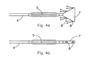
- Fig. 4a shows a top view of an end of a drill pipe 4 with a transmitter housing 5 and an injection head 7 having two pairs of nozzles 8 situated opposite one another connected thereto.
- Hardening substance can be injected into the bore hole and the surrounding earth via the nozzles 8.
- the direction of flow of the injected hardening substance is substantially axial in the longitudinal direction of the bore hole towards the connection with the drill pipe.
- the transmitter housing 5 serves to check the displacement of the injection head 7.
- a transmitter is provided in the transmitter housing which can measure the displacement of the injection head.
- the transmitter housing comprises a swivel which ensures that the injection head 7 does not have to rotate along with the drill pipe 4.
- the transmitter housing preferably comprises a reamer when the drill pipes are retracted through the bore hole in a rotating manner.
- a line may be connected to the reamer for the supply of a flushing agent.
- Fig. 4b shows a side view of the end as illustrated in Fig. 4a .
- the injection head 7 is slab-shaped in the shape of a triangle. At one corner, the injection head 7 is fitted to the transmitter housing 5.
- a curved slab-shaped structure having, for example, vertical strip parts can be formed instead of a flat horizontal slab-shaped structure.
- the pattern of the bore holes determines the ultimate cross section of the structure. It is possible to provide all types of conceivable shapes of structure, such as tubular tunnel structures, using the method according to the invention.
- the invention provides a method by means of which a slab-shaped underground structure can expediently be formed. It is particularly advantageous that the method according to the invention has only a minimal effect on the existing environment and that the method can even be used in the case of existing buildings.
Landscapes
- Engineering & Computer Science (AREA)
- Mining & Mineral Resources (AREA)
- Life Sciences & Earth Sciences (AREA)
- Environmental & Geological Engineering (AREA)
- General Life Sciences & Earth Sciences (AREA)
- Geology (AREA)
- Geochemistry & Mineralogy (AREA)
- Fluid Mechanics (AREA)
- Physics & Mathematics (AREA)
- Hydrology & Water Resources (AREA)
- Paleontology (AREA)
- Civil Engineering (AREA)
- General Engineering & Computer Science (AREA)
- Structural Engineering (AREA)
- Consolidation Of Soil By Introduction Of Solidifying Substances Into Soil (AREA)
- Earth Drilling (AREA)
Claims (10)
- Procédé pour fournir une structure souterraine en forme de dalle comprenant les étapes suivantes consistant à :• mettre en place un dispositif de forage du sol pour introduire une tige de forage (4) avec un trépan contrôlable dans le sol au niveau d'un point d'entrée ;• forer un premier trou de forage contrôlé (2) depuis le point d'entrée (A), au travers du sol, jusqu'à un point de sortie (1B) ;• connecter une tête d'injection (7) à une extrémité de la tige de forage (4) pour injecter un produit durcisseur (3) ;• forer un deuxième trou de forage contrôlé sensiblement parallèle au premier trou de forage, un produit durcisseur étant injecté dans le sol autour du trou de forage sur au moins une partie du second trou de forage, et• rétracter la tige de forage (4) de manière rotative au travers du premier trou de forage (2) et tirer la tête d'injection (7) au travers du trou de forage, et en même temps, injecter un produit durcisseur (3) dans le sol autour du trou de forage sur au moins une partie du trou de forage,caractérisé en ce que le procédé comprend l'étape consistant à :• connecter la tête d'injection (7), au moyen d'une articulation, à la tige de forage.
- Procédé selon la revendication 1, dans lequel la distance de centre à centre (a) entre le deuxième trou de forage et le premier trou de forage après que les trous de forage aient été forés, est au maximum de 100 cm.
- Procédé selon la revendication 1 ou 2, dans lequel on injecte dans un certain nombre de trous de forage adj acents (I, II, III) selon un modèle fixe afin de former la structure en forme de dalle, avec des trous de forage sensiblement parallèles intermédiaires (II) qui sont injectés plus tard.
- Procédé selon la revendication 3, dans lequel la pression d'injection est mesurée pendant que le produit durcisseur (3) est injecté dans le trou de forage intermédiaire.
- Procédé selon l'une quelconque des revendications précédentes, dans lequel un mélange de silicate de sodium est injecté pendant que la tête d'injection (7) est rétractée au travers du trou de forage.
- Procédé selon l'une quelconque des revendications précédentes, dans lequel un puits stockage est prévu à proximité du point d'entrée (A) et/ou à proximité du point de sortie (B) pour collecter du liquide de rinçage au cours du forage.
- Procédé selon l'une quelconque des revendications précédentes, dans lequel un trou de forage (2) est foré en ayant une longueur comprise entre 30 et 1000 mètres.
- Procédé selon l'une quelconque des revendications précédentes, dans lequel les paramètres de processus sont mesurés.
- Procédé selon l'une quelconque des revendications précédentes, dans lequel le trou de forage (2) est rincé avec de la bentonite pendant qu'il est en cours de forage.
- Utilisation de la méthode selon l'une quelconque des revendications 1 à 9 pour le renforcement d'une digue pour la construction d'un caisson de polder.
Applications Claiming Priority (1)
| Application Number | Priority Date | Filing Date | Title |
|---|---|---|---|
| NL1034067A NL1034067C2 (nl) | 2007-06-29 | 2007-06-29 | Werkwijze voor het aanbrengen van een ondergrondse plaatvormige constructie. |
Publications (2)
| Publication Number | Publication Date |
|---|---|
| EP2009225A1 EP2009225A1 (fr) | 2008-12-31 |
| EP2009225B1 true EP2009225B1 (fr) | 2011-12-28 |
Family
ID=38962629
Family Applications (1)
| Application Number | Title | Priority Date | Filing Date |
|---|---|---|---|
| EP08075578A Not-in-force EP2009225B1 (fr) | 2007-06-29 | 2008-06-25 | Procédé pour fournir une structure souterraine en forme de dalle |
Country Status (3)
| Country | Link |
|---|---|
| EP (1) | EP2009225B1 (fr) |
| AT (1) | ATE539226T1 (fr) |
| NL (1) | NL1034067C2 (fr) |
Families Citing this family (1)
| Publication number | Priority date | Publication date | Assignee | Title |
|---|---|---|---|---|
| PL232948B1 (pl) | 2017-03-07 | 2019-08-30 | Bargiel Maciej Tnk Projekt | Urządzenie do bezwykopowego formowania w gruncie przegród betonowych, zwłaszcza zbiorników akumulujących ciepło |
Family Cites Families (11)
| Publication number | Priority date | Publication date | Assignee | Title |
|---|---|---|---|---|
| US3608318A (en) * | 1969-05-12 | 1971-09-28 | Phillips Petroleum Co | Method and apparatus for injecting relatively water-impervious dikes in relatively permeable earth formations,and forming earth-filled tanks and canals therewith |
| US3658131A (en) * | 1970-10-30 | 1972-04-25 | Cities Service Oil Co | Selective plugging method |
| US4900196A (en) * | 1987-11-20 | 1990-02-13 | Iit Research Institute | Confinement in porous material by driving out water and substituting sealant |
| WO1994025688A1 (fr) * | 1993-04-28 | 1994-11-10 | Flowtex Technologie-Import Von Kabelverlegemaschinen Gmbh | Procede permettant de rendre des massifs de terre etanches et dispositif de mise en ×uvre dudit procede |
| FR2746187A1 (fr) * | 1996-03-15 | 1997-09-19 | Electricite De France | Procede et appareillage pour la surveillance de l'injection d'un produit consolidant dans un sol |
| US6105673A (en) * | 1996-11-05 | 2000-08-22 | Harris; Todd K. | Patching of injection and production well annular casing leaks for restoring mechanical integrity |
| DE19940774C2 (de) * | 1999-08-27 | 2003-03-06 | Keller Grundbau Gmbh | Verfahren und Vorrichtung zum Herstellen von flächenhaften Dichtelementen im Erdboden |
| WO2001040583A1 (fr) * | 1999-12-06 | 2001-06-07 | Bechtel Bwxt Idaho, Llc | Systeme de confinement avance |
| US6357968B1 (en) * | 2000-01-12 | 2002-03-19 | Sandia Corporation | Method and apparatus for constructing an underground barrier wall structure |
| US6722433B2 (en) * | 2002-06-21 | 2004-04-20 | Halliburton Energy Services, Inc. | Methods of sealing expandable pipe in well bores and sealing compositions |
| US7182154B2 (en) | 2003-05-28 | 2007-02-27 | Harrison William H | Directional borehole drilling system and method |
-
2007
- 2007-06-29 NL NL1034067A patent/NL1034067C2/nl not_active IP Right Cessation
-
2008
- 2008-06-25 EP EP08075578A patent/EP2009225B1/fr not_active Not-in-force
- 2008-06-25 AT AT08075578T patent/ATE539226T1/de active
Also Published As
| Publication number | Publication date |
|---|---|
| EP2009225A1 (fr) | 2008-12-31 |
| NL1034067C2 (nl) | 2008-12-30 |
| ATE539226T1 (de) | 2012-01-15 |
Similar Documents
| Publication | Publication Date | Title |
|---|---|---|
| AU2020103672A4 (en) | Construction method of rotary drilling hole-forming and jet mixing cement-soil occlusion curtain piles | |
| CN111173038B (zh) | 一种竖井的施工工艺 | |
| CN205172598U (zh) | 管幕旋喷桩支护结构 | |
| CN109931077B (zh) | 用于隧道修复的支护系统及其施工方法 | |
| CN107489158A (zh) | 一种旋挖成孔搅喷水泥土咬合帷幕桩的施工方法 | |
| CN112761166A (zh) | Smw工法桩结合前置注浆钢管组合支护浅基坑施工方法 | |
| KR102609304B1 (ko) | 방향제어 시추공을 이용한 구조물하부 연약지반 및 지하공동 그라우팅 공법 및 이를 위한 그라우팅 시스템. | |
| CN103233469A (zh) | 旋扩桩施工工艺、设备及进浆装置 | |
| CN105926671B (zh) | 地铁车站的地下室支护施工技术 | |
| CN113585289A (zh) | 塌陷性土质深基坑支护方法 | |
| CN102839661A (zh) | 旋搅喷射锚管桩施工工艺 | |
| CN111894598A (zh) | 竖井加固方法 | |
| CN103074887B (zh) | 钻喷一体化地基处理方法及专用钻具组件 | |
| CN209129017U (zh) | 搅拌桩或旋喷桩与袖阀管注浆组合止水帷幕施工结构 | |
| JP4074198B2 (ja) | 既設杭の撤去方法 | |
| CN107700508A (zh) | 一种型钢搅喷水泥土帷幕支护桩的施工方法 | |
| CN116348655A (zh) | 材料和设备的地下部署方法和系统 | |
| EP2009225A1 (fr) | Procédé pour fournir une structure souterraine en forme de dalle | |
| CN103774645B (zh) | 一种水泥土和混凝土组合材料桩的施工方法 | |
| CN115853024B (zh) | 一种防渗墙结构及围堰防渗施工方法 | |
| JP5284168B2 (ja) | 土留部材建込用掘削部材および土留部材建込工法 | |
| CN116752524A (zh) | 高水位连砂石地质条件下抗浮锚杆施工方法 | |
| JP2008045352A (ja) | 谷埋め盛土の地滑り防止工法 | |
| CN112392487A (zh) | 用于强透水岩体下饱和含水砂土层中的洞挖施工方法 | |
| JPH07507362A (ja) | コンクリート構造体を粗い物質に地面レベルから構築する方法および前記方法を実施する設備 |
Legal Events
| Date | Code | Title | Description |
|---|---|---|---|
| PUAI | Public reference made under article 153(3) epc to a published international application that has entered the european phase |
Free format text: ORIGINAL CODE: 0009012 |
|
| AK | Designated contracting states |
Kind code of ref document: A1 Designated state(s): AT BE BG CH CY CZ DE DK EE ES FI FR GB GR HR HU IE IS IT LI LT LU LV MC MT NL NO PL PT RO SE SI SK TR |
|
| AX | Request for extension of the european patent |
Extension state: AL BA MK RS |
|
| 17P | Request for examination filed |
Effective date: 20090609 |
|
| 17Q | First examination report despatched |
Effective date: 20090715 |
|
| AKX | Designation fees paid |
Designated state(s): AT BE BG CH CY CZ DE DK EE ES FI FR GB GR HR HU IE IS IT LI LT LU LV MC MT NL NO PL PT RO SE SI SK TR |
|
| GRAP | Despatch of communication of intention to grant a patent |
Free format text: ORIGINAL CODE: EPIDOSNIGR1 |
|
| RIN1 | Information on inventor provided before grant (corrected) |
Inventor name: DE GROOT, ARVID Inventor name: VAN LEEUWEN, MARINUS TEUNIS, JR Inventor name: MOSSEL, KOR Inventor name: DE GROOT, FRANS |
|
| GRAS | Grant fee paid |
Free format text: ORIGINAL CODE: EPIDOSNIGR3 |
|
| GRAA | (expected) grant |
Free format text: ORIGINAL CODE: 0009210 |
|
| AK | Designated contracting states |
Kind code of ref document: B1 Designated state(s): AT BE BG CH CY CZ DE DK EE ES FI FR GB GR HR HU IE IS IT LI LT LU LV MC MT NL NO PL PT RO SE SI SK TR |
|
| REG | Reference to a national code |
Ref country code: GB Ref legal event code: FG4D |
|
| REG | Reference to a national code |
Ref country code: CH Ref legal event code: EP |
|
| REG | Reference to a national code |
Ref country code: AT Ref legal event code: REF Ref document number: 539226 Country of ref document: AT Kind code of ref document: T Effective date: 20120115 |
|
| REG | Reference to a national code |
Ref country code: IE Ref legal event code: FG4D |
|
| REG | Reference to a national code |
Ref country code: DE Ref legal event code: R096 Ref document number: 602008012285 Country of ref document: DE Effective date: 20120308 |
|
| REG | Reference to a national code |
Ref country code: NL Ref legal event code: VDEP Effective date: 20111228 |
|
| PG25 | Lapsed in a contracting state [announced via postgrant information from national office to epo] |
Ref country code: LT Free format text: LAPSE BECAUSE OF FAILURE TO SUBMIT A TRANSLATION OF THE DESCRIPTION OR TO PAY THE FEE WITHIN THE PRESCRIBED TIME-LIMIT Effective date: 20111228 Ref country code: NO Free format text: LAPSE BECAUSE OF FAILURE TO SUBMIT A TRANSLATION OF THE DESCRIPTION OR TO PAY THE FEE WITHIN THE PRESCRIBED TIME-LIMIT Effective date: 20120328 |
|
| LTIE | Lt: invalidation of european patent or patent extension |
Effective date: 20111228 |
|
| PG25 | Lapsed in a contracting state [announced via postgrant information from national office to epo] |
Ref country code: LV Free format text: LAPSE BECAUSE OF FAILURE TO SUBMIT A TRANSLATION OF THE DESCRIPTION OR TO PAY THE FEE WITHIN THE PRESCRIBED TIME-LIMIT Effective date: 20111228 Ref country code: HR Free format text: LAPSE BECAUSE OF FAILURE TO SUBMIT A TRANSLATION OF THE DESCRIPTION OR TO PAY THE FEE WITHIN THE PRESCRIBED TIME-LIMIT Effective date: 20111228 Ref country code: GR Free format text: LAPSE BECAUSE OF FAILURE TO SUBMIT A TRANSLATION OF THE DESCRIPTION OR TO PAY THE FEE WITHIN THE PRESCRIBED TIME-LIMIT Effective date: 20120329 Ref country code: SE Free format text: LAPSE BECAUSE OF FAILURE TO SUBMIT A TRANSLATION OF THE DESCRIPTION OR TO PAY THE FEE WITHIN THE PRESCRIBED TIME-LIMIT Effective date: 20111228 Ref country code: SI Free format text: LAPSE BECAUSE OF FAILURE TO SUBMIT A TRANSLATION OF THE DESCRIPTION OR TO PAY THE FEE WITHIN THE PRESCRIBED TIME-LIMIT Effective date: 20111228 |
|
| PG25 | Lapsed in a contracting state [announced via postgrant information from national office to epo] |
Ref country code: CY Free format text: LAPSE BECAUSE OF FAILURE TO SUBMIT A TRANSLATION OF THE DESCRIPTION OR TO PAY THE FEE WITHIN THE PRESCRIBED TIME-LIMIT Effective date: 20111228 Ref country code: BE Free format text: LAPSE BECAUSE OF FAILURE TO SUBMIT A TRANSLATION OF THE DESCRIPTION OR TO PAY THE FEE WITHIN THE PRESCRIBED TIME-LIMIT Effective date: 20111228 |
|
| PG25 | Lapsed in a contracting state [announced via postgrant information from national office to epo] |
Ref country code: IS Free format text: LAPSE BECAUSE OF FAILURE TO SUBMIT A TRANSLATION OF THE DESCRIPTION OR TO PAY THE FEE WITHIN THE PRESCRIBED TIME-LIMIT Effective date: 20120428 Ref country code: BG Free format text: LAPSE BECAUSE OF FAILURE TO SUBMIT A TRANSLATION OF THE DESCRIPTION OR TO PAY THE FEE WITHIN THE PRESCRIBED TIME-LIMIT Effective date: 20120328 Ref country code: CZ Free format text: LAPSE BECAUSE OF FAILURE TO SUBMIT A TRANSLATION OF THE DESCRIPTION OR TO PAY THE FEE WITHIN THE PRESCRIBED TIME-LIMIT Effective date: 20111228 Ref country code: SK Free format text: LAPSE BECAUSE OF FAILURE TO SUBMIT A TRANSLATION OF THE DESCRIPTION OR TO PAY THE FEE WITHIN THE PRESCRIBED TIME-LIMIT Effective date: 20111228 Ref country code: NL Free format text: LAPSE BECAUSE OF FAILURE TO SUBMIT A TRANSLATION OF THE DESCRIPTION OR TO PAY THE FEE WITHIN THE PRESCRIBED TIME-LIMIT Effective date: 20111228 Ref country code: EE Free format text: LAPSE BECAUSE OF FAILURE TO SUBMIT A TRANSLATION OF THE DESCRIPTION OR TO PAY THE FEE WITHIN THE PRESCRIBED TIME-LIMIT Effective date: 20111228 |
|
| PG25 | Lapsed in a contracting state [announced via postgrant information from national office to epo] |
Ref country code: PL Free format text: LAPSE BECAUSE OF FAILURE TO SUBMIT A TRANSLATION OF THE DESCRIPTION OR TO PAY THE FEE WITHIN THE PRESCRIBED TIME-LIMIT Effective date: 20111228 Ref country code: RO Free format text: LAPSE BECAUSE OF FAILURE TO SUBMIT A TRANSLATION OF THE DESCRIPTION OR TO PAY THE FEE WITHIN THE PRESCRIBED TIME-LIMIT Effective date: 20111228 Ref country code: PT Free format text: LAPSE BECAUSE OF FAILURE TO SUBMIT A TRANSLATION OF THE DESCRIPTION OR TO PAY THE FEE WITHIN THE PRESCRIBED TIME-LIMIT Effective date: 20120430 |
|
| REG | Reference to a national code |
Ref country code: AT Ref legal event code: MK05 Ref document number: 539226 Country of ref document: AT Kind code of ref document: T Effective date: 20111228 |
|
| PG25 | Lapsed in a contracting state [announced via postgrant information from national office to epo] |
Ref country code: DK Free format text: LAPSE BECAUSE OF FAILURE TO SUBMIT A TRANSLATION OF THE DESCRIPTION OR TO PAY THE FEE WITHIN THE PRESCRIBED TIME-LIMIT Effective date: 20111228 |
|
| PLBE | No opposition filed within time limit |
Free format text: ORIGINAL CODE: 0009261 |
|
| STAA | Information on the status of an ep patent application or granted ep patent |
Free format text: STATUS: NO OPPOSITION FILED WITHIN TIME LIMIT |
|
| PG25 | Lapsed in a contracting state [announced via postgrant information from national office to epo] |
Ref country code: IT Free format text: LAPSE BECAUSE OF FAILURE TO SUBMIT A TRANSLATION OF THE DESCRIPTION OR TO PAY THE FEE WITHIN THE PRESCRIBED TIME-LIMIT Effective date: 20111228 |
|
| 26N | No opposition filed |
Effective date: 20121001 |
|
| REG | Reference to a national code |
Ref country code: DE Ref legal event code: R097 Ref document number: 602008012285 Country of ref document: DE Effective date: 20121001 |
|
| PG25 | Lapsed in a contracting state [announced via postgrant information from national office to epo] |
Ref country code: MC Free format text: LAPSE BECAUSE OF NON-PAYMENT OF DUE FEES Effective date: 20120630 Ref country code: AT Free format text: LAPSE BECAUSE OF FAILURE TO SUBMIT A TRANSLATION OF THE DESCRIPTION OR TO PAY THE FEE WITHIN THE PRESCRIBED TIME-LIMIT Effective date: 20111228 |
|
| REG | Reference to a national code |
Ref country code: CH Ref legal event code: PL |
|
| REG | Reference to a national code |
Ref country code: CH Ref legal event code: PL |
|
| GBPC | Gb: european patent ceased through non-payment of renewal fee |
Effective date: 20120625 |
|
| REG | Reference to a national code |
Ref country code: IE Ref legal event code: MM4A |
|
| REG | Reference to a national code |
Ref country code: FR Ref legal event code: ST Effective date: 20130228 |
|
| REG | Reference to a national code |
Ref country code: DE Ref legal event code: R119 Ref document number: 602008012285 Country of ref document: DE Effective date: 20130101 |
|
| PG25 | Lapsed in a contracting state [announced via postgrant information from national office to epo] |
Ref country code: FR Free format text: LAPSE BECAUSE OF NON-PAYMENT OF DUE FEES Effective date: 20120702 Ref country code: CH Free format text: LAPSE BECAUSE OF NON-PAYMENT OF DUE FEES Effective date: 20120630 Ref country code: IE Free format text: LAPSE BECAUSE OF NON-PAYMENT OF DUE FEES Effective date: 20120625 Ref country code: GB Free format text: LAPSE BECAUSE OF NON-PAYMENT OF DUE FEES Effective date: 20120625 Ref country code: LI Free format text: LAPSE BECAUSE OF NON-PAYMENT OF DUE FEES Effective date: 20120630 Ref country code: DE Free format text: LAPSE BECAUSE OF NON-PAYMENT OF DUE FEES Effective date: 20130101 Ref country code: ES Free format text: LAPSE BECAUSE OF FAILURE TO SUBMIT A TRANSLATION OF THE DESCRIPTION OR TO PAY THE FEE WITHIN THE PRESCRIBED TIME-LIMIT Effective date: 20120408 |
|
| PG25 | Lapsed in a contracting state [announced via postgrant information from national office to epo] |
Ref country code: FI Free format text: LAPSE BECAUSE OF FAILURE TO SUBMIT A TRANSLATION OF THE DESCRIPTION OR TO PAY THE FEE WITHIN THE PRESCRIBED TIME-LIMIT Effective date: 20111228 |
|
| PG25 | Lapsed in a contracting state [announced via postgrant information from national office to epo] |
Ref country code: MT Free format text: LAPSE BECAUSE OF FAILURE TO SUBMIT A TRANSLATION OF THE DESCRIPTION OR TO PAY THE FEE WITHIN THE PRESCRIBED TIME-LIMIT Effective date: 20111228 |
|
| PG25 | Lapsed in a contracting state [announced via postgrant information from national office to epo] |
Ref country code: TR Free format text: LAPSE BECAUSE OF FAILURE TO SUBMIT A TRANSLATION OF THE DESCRIPTION OR TO PAY THE FEE WITHIN THE PRESCRIBED TIME-LIMIT Effective date: 20111228 |
|
| PG25 | Lapsed in a contracting state [announced via postgrant information from national office to epo] |
Ref country code: LU Free format text: LAPSE BECAUSE OF NON-PAYMENT OF DUE FEES Effective date: 20120625 |
|
| PG25 | Lapsed in a contracting state [announced via postgrant information from national office to epo] |
Ref country code: HU Free format text: LAPSE BECAUSE OF FAILURE TO SUBMIT A TRANSLATION OF THE DESCRIPTION OR TO PAY THE FEE WITHIN THE PRESCRIBED TIME-LIMIT Effective date: 20080625 |