EP2009226B1 - Appareil et procédé pour étancher un espace annulaire - Google Patents
Appareil et procédé pour étancher un espace annulaire Download PDFInfo
- Publication number
- EP2009226B1 EP2009226B1 EP08012835.8A EP08012835A EP2009226B1 EP 2009226 B1 EP2009226 B1 EP 2009226B1 EP 08012835 A EP08012835 A EP 08012835A EP 2009226 B1 EP2009226 B1 EP 2009226B1
- Authority
- EP
- European Patent Office
- Prior art keywords
- fluid
- pressure
- area
- annulus
- working fluid
- Prior art date
- Legal status (The legal status is an assumption and is not a legal conclusion. Google has not performed a legal analysis and makes no representation as to the accuracy of the status listed.)
- Active
Links
Images


Classifications
-
- E—FIXED CONSTRUCTIONS
- E21—EARTH OR ROCK DRILLING; MINING
- E21B—EARTH OR ROCK DRILLING; OBTAINING OIL, GAS, WATER, SOLUBLE OR MELTABLE MATERIALS OR A SLURRY OF MINERALS FROM WELLS
- E21B33/00—Sealing or packing boreholes or wells
- E21B33/02—Surface sealing or packing
- E21B33/03—Well heads; Setting-up thereof
- E21B33/068—Well heads; Setting-up thereof having provision for introducing objects or fluids into, or removing objects from, wells
- E21B33/072—Well heads; Setting-up thereof having provision for introducing objects or fluids into, or removing objects from, wells for cable-operated tools
Definitions
- the present invention relates to an apparatus and method for creating a localised area of high pressure within a conduit and a method for retaining pressure within an annulus.
- the invention is useful for containing well pressure while performing wireline operations.
- US 2006/0157282 describes a method and apparatus for dynamically controlling pressure in a wellbore while forming the wellbore in which one or more pressure control apparatus are used to maintain desired pressure.
- a method for containing fluid in an area of a wellbore annulus comprising the steps of:
- the energised fluid may seal the annulus in the localised area of high pressure, such that escape of fluid from regions of ambient pressure is restricted or prevented.
- Step (a) can include accelerating the fluid flow.
- Step (a) can include increasing the speed of fluid to a speed between 20-600 m/s.
- the jet has sufficient velocity to overcome the ambient pressure, (for example, the pressure at the outlet of the channel) so that it reaches the obstruction of step (b).
- Step (b) can include impeding or placing an impediment in a path of the energised fluid.
- Step (b) can include at least partially confining the fluid in a chamber and/or can include at least partially confining the energised fluid in a predetermined area of the annulus.
- the chamber may define an annular space.
- Steps (b) and (c) can be performed simultaneously.
- Step (c) can include angling the surface such that flow is directed to generate a localised area of higher pressure in a predetermined region.
- Step (c) of the method can include deflecting the fluid flow to generate an area of higher pressure in the annulus.
- the method may include deflecting the fluid flow toward the area of higher pressure.
- the method may include deflecting the fluid flow to generate a pressure plug in the area of higher pressure.
- the pressure plug and/or area of high pressure may separate first and second regions of lower pressure, and may restrict or prevent fluid flow between the first and second regions.
- the plug and/or area of high pressure may contain, act as a barrier to, seal against, cap and/or act as a fluid wall for well fluid located downhole, and may prevent flow of fluid from the downhole location to a second region uphole in relation to the first region.
- the first and second regions thus, may be regions of the wellbore annulus.
- the wellbore annulus may be an annular space defined between a wireline or slickline, and an inner wall of a wellbore or other wellbore equipment, for example, a pressure control head, stuffing box, wellbore tubing or open hole formations.
- the method can include a further step (d) of collecting fluid as the localised area of higher pressure dissipates to the ambient pressure.
- the method can further include recycling the fluid in step (d) by performing step (a) on the collected fluid.
- the method may include circulating fluid into and out of said area for maintaining the area of high pressure spatially and over a period time.
- fluid is moved through the high pressure region.
- the area of high pressure and/or pressure plug separates first and second regions of lower pressure
- the second region is at a lower pressure than that of the first region, to provide for fluid flow or dissipation of fluid from the high pressure region to the second region of lower pressure.
- the high pressure area or pressure plug may form an interface separating the first and second regions.
- Energised fluid used to create the high pressure area may be collected from the second region of lower pressure for repeat use. Fluid may flow from the high pressure region to the second region in preference to the first region, to maintain the pressure conditions of the high pressure region, whilst containing fluid in the first region.
- the method can involve containing an ambient pressure in an annulus of a wellbore by performing the method previously described downstream of the intended containment region.
- the method can include selecting the parameters for fluid speed and the obstruction such that the localised area of high pressure acts as a plug of high pressure to contain the ambient pressure.
- Such parameters may include, speed of fluid, direction of fluid flow, channel dimensions, relative position and orientation of the channel to the annulus, relative position and/or orientation of the channel to the angled surface.
- the method can include selecting a fluid having a viscosity of less than 10 centipoise (0.1 Pa s).
- an apparatus for containing a fluid in a wellbore annulus comprising:
- the obstruction of fluid flow creates a back pressure, by presenting an obstacle to the flow of the fluid.
- the energised fluid may plug or seal the annulus at said area of high pressure.
- the obstruction is formed from a material having an excellent wear resistance.
- the fluid can be water.
- the water can include additives such as corrosion inhibitors.
- the fluid can have a viscosity of around 1-5 centipoise (1-5x10 -2 Pa s).
- the apparatus comprises a channel having a fluid inlet and a fluid outlet wherein the channel has a smaller sectional area in the region of the outlet than that of the inlet to increase fluid velocity in the region of the outlet for jetting the fluid into the localised area of high pressure
- the means for energising a fluid can comprise a body having a channel with an inlet for receiving a fluid and an outlet, and wherein at least a portion of the channel converges towards the outlet.
- the portion of the channel that converges towards the outlet can have a lower sectional area, which increases the velocity of fluid within that portion of the channel.
- the apparatus and/or body can have a throughbore.
- the throughbore may be arranged to receive a line and wherein the obstruction can be arranged and/or positioned such that pressure is generated in an annular space between the throughbore and the line.
- the body and the channel can form a symmetrical concentric nozzle for producing an annular jet of energised fluid.
- the obstruction and/or means for directing the fluid may include a deflector insert located in the throughbore.
- the deflector insert may be removably attached to a main body of the apparatus.
- the deflector insert and/or inner surface of the throughbore may include an angled and/or shaped surface.
- the deflector insert and/or inner surface of the throughbore may have an inwardly protruding member, which may in turn include the angled and/or shaped surface placed in the path of energised fluid.
- the shaped surface may extend inwardly to partially occlude an annular space which may be formed around a line received in the throughbore.
- the obstruction and/or means for directing the fluid may include a nozzle insert located in the throughbore.
- the nozzle insert may be removably attached to a main body of the apparatus, and together with the main body may define a channel for jetting fluid into the wellbore annulus.
- the nozzle insert together with the deflector insert may be arranged to help energise, direct and obstruct the fluid to create said high pressure area and/or pressure plug.
- the width of the annulus can be approximately 0.05 to 1.0 inch (1.27 to 25.4 mm).
- the angle of the surface relative to an axis of the conduit can be selected according to the desired application.
- the angle of the surface relative to an axis of the conduit can be selected to deflect the fluid flow to create an area of localised pressure in the predetermined position.
- the obstruction and the directing means may together define a geometry which interacts with the energised fluid permitting sufficient pressure build up to generate a pressure plug in the annulus from the energised fluid.
- the obstruction, together with the means for directing the fluid may be adapted to create the localised area of high pressure in the annulus. This geometry may facilitate pressure build-up on directing energised fluid to the annulus.
- the geometry may be based on selected parameters for the fluid flow, such as required fluid flow speeds and/or other parameters.
- the surface can be cone-shaped in section.
- the cone angle can be between 20° and 60° from the axis of the conduit.
- the cone angle can be defined as the angle of the surface relative top the axis of the conduit.
- the surface can be lens-shaped and/or concave.
- the invention is advantageous for use in a wellbore to contain a pressure within an annulus as it reduces the amount of equipment space required, increases safety margins and reduces contamination of the surrounding environment.
- the annulus can be created by running a line, such as wireline or slickline through a tubing.
- the line can be selected from the group consisting of: wireline; slickline; and downhole tubing.
- the annulus may be formed between a wireline and an inner wall of a throughbore for receiving the line.
- the inner wall may have a recess, step, angled surface, inwardly protruding member or be otherwise shaped for interacting with a fluid and/or to assist energising a fluid.
- the fluid may be jetted into the annulus through the inner wall of the throughbore.
- the wall may at least partially act as an obstruction, or a deflector for energised fluid.
- the minimum predetermined velocity can be 20 m/s. More preferably, the minimum predetermined velocity can be 40 m/s. Alternatively, the value for the minimum predetermined velocity can be any value up to around 600 m/s, depending on the application and the pressures in the annulus that need to be contained.
- the fluid has a lower viscosity than a long-chain hydrocarbon, such as grease.
- the fluid has a viscosity around a factor of 100 times less viscous than a long chain hydrocarbon.
- the method can include shaping the surface to deflect the fluid to a predetermined region such that the back pressure forms a pressure plug in the annulus.
- the method may include shaping a surface for deflecting fluid to a predetermined region in the annulus and thereby facilitate creating the area of higher pressure.
- the apparatus may take the form of a pressure control head, a stuffing box and/or any other pressure control apparatus for wellbore tubing.
- the second aspect of the invention can include any previously described features or method steps of the first aspect of the invention, where appropriate.
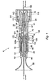
- a pressure control head is shown generally at 8 in Fig. 1 .
- the pressure control head 8 has four main portions: a collar 110; a body 10; a housing 40; and a funnel 50.
- the collar 110 is connected to the body 10 at a coupling 111.
- the body 10 is substantially cylindrical and is formed with a centrally disposed throughbore 13 having a flared portion 13f for accommodating inserts (described hereinafter).
- An inlet port 22 extends through a sidewall of the body 10 and an outlet port 44 also extends through the sidewall of the body 10. Both the inlet port 22 and the outlet port 44 are in fluid communication with the throughbore 13.
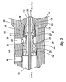
- the flared throughbore portion 13f of the body 10 is arranged to receive a deflector insert 20.
- the deflector insert 20 engages the body 10 by means of a threaded connection 21.
- An outer surface of the deflector insert 20 is provided with an annular groove 25 that accommodates an annular seal 26 to create a fluid tight seal between the exterior of the deflector insert 20 and the throughbore 13.
- the deflector insert 20 has a central passageway or throughbore 23 for receiving a wireline.
- Part of the throughbore 13 is shaped as a frustocone having an impact surface 28 with a cone angle of around 50° relative to its axis of symmetry.
- the throughbore 23 of the deflector insert 20 opens out into a diverging annular side wall 27.
- the impact surface 28 of the deflector insert 20 is formed from a ceramic material that has excellent wear resistance.
- the flared throughbore portion 13f also has an annular step 13s positioned adjacent the part of the body 10 where the inlet port 22 communicates with the throughbore 13.
- a nozzle insert 30 having a central passageway or throughbore 33 for receiving a wireline is positioned within the body 10 so that a portion of the nozzle insert 30 abuts the annular step 13s.
- the nozzle insert 30 is provided with a shaped protrusion 38 at one end that extends into the throughbore 23 of the deflector insert 20.
- the protrusion 38 of the nozzle insert 30 has an outer annular side wall 35.
- the outer side wall 35 of the nozzle insert 30 and the annular inner side wall 27 of the deflector insert 20 forms a concentric annular channel that acts as a convergent nozzle 31.
- An inlet of the nozzle 31 is in communication with an annular chamber 37 and hence the inlet port 22 extending through the sidewall of the body 10.
- the inlet port 22 is connected to a pump (not shown) to inject fluid through the port 22, into the chamber and the nozzle 31.
- the exterior of the nozzle insert 30 is provided with an annular groove 39 that accommodates an annular seal 34 to create a fluid tight seal between the flared throughbore portion 13f and the exterior of the nozzle insert 30.
- the annular seals 26, 34 act to isolate the lower chamber 37 such that fluid entering through the inlet port 22 can only escape via the nozzle 31.
- the housing 40 has a box end coupled to a pin end of the body 10, by means of a threaded connection 121.
- the housing 40 is substantially cylindrical and has a hollow interior 43 that houses an annular piston 120, a seal cone 70, a spring 80 and a wiper 60.
- the annular piston 120 is substantially cylindrical and one end is slidably disposed in the flared throughbore portion 13f.
- a piston head 120h abuts and end face 10e of the body 10.
- An upper chamber 46 is formed in the flared throughbore portion 13f between the nozzle insert 30 and the annular piston 120. The upper chamber 46 is in fluid communication with the outlet port 44.
- the pin end of the body 10 has an annular groove 14 on its exterior and an annular groove 15 on its interior for accommodating annular seals 122.
- the exterior of the piston head 120h is provided with an annular groove 123 that accommodates an annular seal 122. All the seals 122 fluidly isolate an annular chamber 126 that is in fluid communication with a pump (not shown) via a port 128 extending through a sidewall of the housing 40.
- the spring 80 is retained between the housing 40 and the piston head 120h, so that the annular piston 120 is resiliently urged to abut the end face 10e of the body 10.
- the seal cone 70 is attached to the piston 120 and has an angled annular face that abuts the wiper 60.
- the wiper 60 is typically a polymer disposed within the housing 40 and the wiper 60 is compressible by the action of the seal cone 70 thereon.
- the funnel 50 has a pin end and is attached to a box end of the housing 40 via a threaded connection 51.
- the funnel 50 is arranged with its divergent end distal from the housing 40.
- the funnel 50 is provided with a centraliser 90 for centralising a wireline running therethrough.
- the centraliser 90 also acts as a barrier against which the wiper 60 can react under the force of the seal cone 70 acting thereagainst.
- An outlet port 52 extending through a sidewall of the funnel 50 is provided to recover fluids collected in the funnel 50.
- a wireline 130 is shown in Figs. 1 to 6 centrally disposed in the throughbores 13, 23, 33 of the pressure control head 8.
- the throughbores 13, 23, 33 of the components making up the pressure control head 8 shown in Fig. 1 form a continuous throughbore that allows a wireline 130 to run unimpeded therethrough.
- An annular space 112 is created between the wireline 130 and the throughbores 13, 23, 33.
- the annular space 112 is substantially continuous through the body 10, the deflector insert 20 and the nozzle insert 30.
- the pressure control head 8 Prior to use, the pressure control head 8 is assembled in the form shown in Fig. 1 .
- the deflector insert 20 followed by the nozzle insert 30 are screwed into the flared throughbore portion 13f of the body 10.
- the piston 120 is inserted into an upper end of the body 10 such that the end face 10e of the body abuts the piston head 120h.
- the spring 80 is compressed between the piston 120 and the funnel 50 prior to making up the connections.
- Connections 111, 121, 51, are made up respectively, between the body 10 and the collar 110, the body 10 and the housing 40 and the housing 40 and the funnel 50.
- the pressure control head 8 is then incorporated in a downhole tubing string such that the divergent end of the funnel 50 is located upstream of (closer to surface than) the collar 110 that forms the lowermost part of the assembly closest to the downhole environment.
- the wireline 130 can then be run downhole through the pressure control head 8.
- the method of the invention is used to contain these downhole pressures and substantially restrict the escape of downhole fluids via leak paths in the annulus 112 between the throughbores 13, 23, 33 and the exterior of the braided wireline 130.
- the diameter of the wireline 130 is 0.312 inches (7.9 mm).
- the pump connected to the inlet port 22 pumps a working fluid into the chamber 37.
- the working fluid is water and can be used with some anti-corrosion additives to limit the corrosive potential of the fluid to the wireline 130, the pressure control head 8 and other downhole components.
- Continued pumping of fluid into the lower chamber 37 forces fluid through the nozzle 31.
- the dimensions of the nozzle 31 and specifically, the fact that the nozzle 31 converges towards its outlet causes the fluid to accelerate, thereby increasing the speed of the fluid until it exits the nozzle 31 at the outlet in a relatively high velocity jet having a speed of around 500 m/s.
- the fluid jet impacts against the impact surface 28, which acts as an obstruction in the path of the jet.
- the effect of the high velocity fluid impacting against the impact surface 28 is that a large back pressure is generated due to the surface presenting an impediment to the high speed fluid flow.
- the 50° cone angle of the impact surface 28 deflects the fluid flow towards the wireline 130.
- a localised area of high pressure is thereby formed in the annulus 112 surrounding the wireline 130. This acts as a pressure plug.
- the schematic diagram shown in Fig. 3 indicates the direction of fluid flow. Arrows 114 indicate the direction in which the downhole pressures are acting.
- the pressure plug is at a higher pressure than the downhole pressure and therefore contains the downhole fluids at pressure that would otherwise escape in the direction of the arrows 114.
- the fluid exiting the outlet of the nozzle 31 must have sufficient velocity to overcome the pressure acting against the direction of fluid flow (shown by the arrows 114) in the annulus 112.
- the small containment region between the nozzle 31 outlet, the impact surface 28 and the wireline 130 obstructs the fluid flow and thereby plugs the annulus to prevent the escape of high pressures.
- the working fluid then dissipates in the annulus 112 and the pressure decreases away from the region of the high pressure plug.
- working fluid flows into, through and then out from the region of the high pressure plug toward the chamber 46.
- the pressure away from the pressure plug near the chamber 46 is at a lower pressure than that of the wellbore fluids contained downhole. Since the working fluid is continuously pumped and circulated through the nozzle 31, the effect of the pressure plug is continuously maintained.
- the method of the invention can be used both as the wireline 130 is run downhole and pulled from the wellbore.
- the wiper 60 can be urged into contact with the wireline 130 to remove excess fluid. This is achieved by injecting a hydraulic fluid through the port 128 into the chamber 126. Fluid in the chamber 126 acts against the piston head 121 to urge upward movement of the piston 120 and hence the attached seal cone 70 against the bias of the spring 80 to force the wiper 60 into contact with the wireline 130 to remove excess fluids therefrom.
- the funnel 50 is shaped to collect any remaining drips from the wireline 130 that are then recovered through the port 52 and recycled if required.
- the deflector insert 20 is advantageously provided as a separate component that is coupled to the body 10.
- the deflector insert 20 and in particular, the impact surface 28 of the frustocone is prone to wear and can be easily removed and replaced because it is separable from the body 10. This also applies to the nozzle insert 30 if it is damaged or suffers wear.
- the nozzle 31 should be sized to suit a large range of wireline diameters, thus, eliminating the need for bespoke equipment depending on wireline diameter.
- the deflector insert 20 and the nozzle insert 30 are separate components that together determine the shape of the nozzle 31 through which the working fluid is directed (and hence the fluid speed) allows the dimensions of the channel to be easily altered for different applications or ranges of wireline 130 size.
- the nozzle insert 30 can be removable so that it may be replaced by a nozzle insert 30 having a steeper annular sidewall 35 to vary the speed of the fluid exiting the nozzle. Therefore, several different deflector inserts 20 and nozzle inserts 30 can be provided having differently sized throughbores 23, 33 to facilitate use of the apparatus with different sizes of wireline 130.
- the shape of the impact surface 28 and the geometry of the confined area can be modified to obstruct the fluid flow to create the back pressure and deflect the fluids to the desired region around the wireline 130.
- the cone angle of the impact surface 28 is 50° relative to the axis of the wireline 130. This is the preferred embodiment.
- a steeper cone angle may be used, as shown in Fig. 6 , where the cone angle of an impact surface 28g is 25 ° from the axis of the wireline 130.
- the 50° cone angle provides a more consistent pressure region in the area of the wireline 130.
- a lens shaped or concave surface 28I can be provided.
- the lens shaped surface 28I has the advantage that the smooth edges reduce the risk of cavitation caused by the turbulent flow of fluid.
- nozzle 31 is not required to be concentric. Instead, individual nozzle outlets can create individual jets of fluid flow that create the same cumulative effect by forming a pressure plug in the annulus.
- the working fluid is not limited to water and can be any suitable fluid that has a viscosity below around 10 centipoise (0.1 Pa s).
Landscapes
- Life Sciences & Earth Sciences (AREA)
- Engineering & Computer Science (AREA)
- Geology (AREA)
- Mining & Mineral Resources (AREA)
- Physics & Mathematics (AREA)
- Environmental & Geological Engineering (AREA)
- Fluid Mechanics (AREA)
- General Life Sciences & Earth Sciences (AREA)
- Geochemistry & Mineralogy (AREA)
- Disintegrating Or Milling (AREA)
- Jet Pumps And Other Pumps (AREA)
- Sealing Devices (AREA)
Claims (11)
- Un procédé pour contenir du fluide dans une zone d'un annulaire de puits de forage (112), le procédé comprenant les étapes consistant à :(a) exciter un fluide moteur comprenant un liquide à faible viscosité et/ou à base d'eau afin de créer un jet de fluide moteur à haute vélocité ;(b) diriger le jet de fluide moteur à haute vélocité pour qu'il vienne cogner contre une surface façonnée (28) obstruant de ce fait partiellement le jet de fluide moteur à haute vélocité(c) et créer de ce fait une contre-pression dans une zone localisée de l'annulaire afin de contenir du fluide dans une zone de l'annulaire (112) à plus basse pression caractérisé en ce que
l'étape (a) est obtenue en faisant passer le fluide dans un canal (31) présentant une entrée de fluide et une sortie de fluide, le canal ayant une superficie en coupe dans la région de la sortie plus petite que celle de l'entrée afin d'augmenter la vélocité du fluide dans la région de la sortie pour lancer le fluide en jet dans la zone localisée de haute pression. - Un procédé selon la revendication 1, le procédé incluant le fait de dévier le jet de fluide moteur à haute vélocité afin de générer un bouchon de pression dans la zone de plus haute pression.
- Un procédé selon la revendication 2, le procédé incluant le fait de façonner une surface (28) pour dévier le jet de fluide moteur à haute vélocité sur une région prédéterminée dans l'annulaire et faciliter de ce fait la création de la zone de plus haute pression.
- Un procédé selon n'importe quelle revendication précédente, le procédé incluant le fait de sélectionner un fluide moteur ayant une viscosité inférieure à 10 centipoises (0,1 Pa s).
- Un procédé selon n'importe quelle revendication précédente, le procédé incluant le fait de faire circuler le fluide moteur dans et hors de ladite zone pour maintenir la zone de haute pression spatialement et sur un laps temps.
- Un procédé selon n'importe quelle revendication précédente, dans lequel l'étape (a) inclut le fait d'augmenter la vitesse du jet de fluide moteur à haute vélocité jusqu'à entre 20 et 600 m/s dans l'annulaire.
- Un procédé selon n'importe quelle revendication précédente, dans lequel l'étape (b) inclut le fait d'entraver la voie d'écoulement du fluide excité.
- Un procédé selon n'importe quelle revendication précédente, dans lequel l'étape (b) inclut le fait de confiner au moins partiellement le fluide moteur dans une zone prédéterminée de l'annulaire.
- Un appareil pour contenir un fluide dans un annulaire de puits de forage (112) comprenant :un moyen pour exciter un fluide comprenant un liquide à faible viscosité et/ou à base d'eau afin de former un jet de fluide moteur à haute vélocité ;une obstruction sous la forme d'une surface façonnée (28) ;un moyen pour amener ledit écoulement du fluide moteur à cogner contre la surface ; etun moyen (20) pour diriger le jet de fluide moteur à haute vélocité sur l'annulaire de puits de forage afin de créer dans l'annulaire une zone localisée de haute pression suffisante pour contenir du fluide dans une zone de l'annulaire de puits de forage à pression ambiante, ledit moyen de direction comprenant une surface (28) orientée à un angle relativement à la direction d'écoulement de fluide et caractérisé en ce que le moyen pour exciter le fluide inclut un canal (31) ayant une entrée de fluide et une sortie de fluide, le canal ayant une superficie en coupe dans la région de la sortie plus petite que celle de l'entrée afin d'augmenter la vélocité du fluide dans la région de la sortie pour lancer le fluide en jet dans la zone localisée de haute pression.
- Appareil selon n'importe lesquelles des revendications 9, dans lequel l'appareil inclut un alésage débouchant (13) conçu pour recevoir un câble (130) dedans, et l'obstruction est positionnée afin de générer une haute pression dans un espace annulaire entre l'alésage débouchant et le câble.
- Appareil selon n'importe lesquelles des revendications 9 ou 10, dans lequel l'obstruction (28) et le moyen de direction (20) définissent ensemble une géométrie qui interagit avec le jet de fluide moteur à haute vélocité permettant une accumulation de pression suffisante pour générer un bouchon de pression dans l'annulaire à partir du fluide excité.
Applications Claiming Priority (1)
| Application Number | Priority Date | Filing Date | Title |
|---|---|---|---|
| GBGB0712528.9A GB0712528D0 (en) | 2007-06-28 | 2007-06-28 | Apparatus and method |
Publications (3)
| Publication Number | Publication Date |
|---|---|
| EP2009226A2 EP2009226A2 (fr) | 2008-12-31 |
| EP2009226A3 EP2009226A3 (fr) | 2011-07-06 |
| EP2009226B1 true EP2009226B1 (fr) | 2013-04-17 |
Family
ID=38420846
Family Applications (1)
| Application Number | Title | Priority Date | Filing Date |
|---|---|---|---|
| EP08012835.8A Active EP2009226B1 (fr) | 2007-06-28 | 2008-07-16 | Appareil et procédé pour étancher un espace annulaire |
Country Status (4)
| Country | Link |
|---|---|
| US (1) | US7997334B2 (fr) |
| EP (1) | EP2009226B1 (fr) |
| CA (1) | CA2636531C (fr) |
| GB (2) | GB0712528D0 (fr) |
Families Citing this family (6)
| Publication number | Priority date | Publication date | Assignee | Title |
|---|---|---|---|---|
| GB0712528D0 (en) | 2007-06-28 | 2007-08-08 | Phuel Oil Tools Ltd | Apparatus and method |
| US8863830B2 (en) | 2009-03-13 | 2014-10-21 | Schlumberger Technology Corporation | Pressure control device for wireline cables and method |
| US8443878B2 (en) * | 2009-07-21 | 2013-05-21 | Hunting Energy Services, Inc. | Dual stripper assembly for slick cable |
| GB201121008D0 (en) * | 2011-12-07 | 2012-01-18 | Nat Oilwell Varco Uk Ltd | Apparatus & method |
| DE102014111649A1 (de) * | 2014-08-14 | 2016-02-18 | Thyssenkrupp Ag | Unterwasserfahrzeug, Verfahren zum Aufnehmen einer Last vom Meeresgrund und ein Verfahren zum Absetzen einer Last am Meeresgrund |
| AU2023239015A1 (en) * | 2022-03-24 | 2024-10-17 | Ferro Supply LLC | Wireline saver tool |
Family Cites Families (19)
| Publication number | Priority date | Publication date | Assignee | Title |
|---|---|---|---|---|
| US1521390A (en) * | 1922-04-07 | 1924-12-30 | Charles B Reynolds | Mud and oil stripper |
| US2176323A (en) * | 1937-12-24 | 1939-10-17 | George W Bowen | Swivel |
| US3145995A (en) * | 1959-04-24 | 1964-08-25 | Halliburton Co | Well service cable sealing apparatus |
| US3606347A (en) | 1969-02-28 | 1971-09-20 | Dresser Ind | Wireline wipers |
| GB1466677A (en) | 1974-02-19 | 1977-03-09 | Phido Co Ltd | Cable cleaning unit |
| US3943997A (en) * | 1974-12-12 | 1976-03-16 | Davis Haggai D | Rotary drilling apparatus and method |
| GB1526952A (en) | 1975-03-14 | 1978-10-04 | Phido Co Ltd | Cable cleaning unit |
| US4235727A (en) * | 1978-04-06 | 1980-11-25 | Union Camp Corporation | Humate thinners for drilling fluids |
| US4279300A (en) * | 1980-01-25 | 1981-07-21 | Exxon Production Research Company | Treating fluid applicator |
| US4476924A (en) * | 1983-03-07 | 1984-10-16 | Camco, Incorporated | Grease injection control head having a specific gas trap |
| US4529210A (en) * | 1983-04-01 | 1985-07-16 | Biffle Morris S | Drilling media injection for rotating blowout preventors |
| US4640372A (en) * | 1985-11-25 | 1987-02-03 | Davis Haggai D | Diverter including apparatus for breaking up large pieces of formation carried to the surface by the drilling mud |
| US4832128A (en) | 1986-10-17 | 1989-05-23 | Shell Pipe Line Corporation | Wellhead assembly for injection wells |
| GB8716777D0 (en) | 1987-07-16 | 1987-08-19 | Earl Eng Ltd | Blow-out preventing valve |
| US4821799A (en) * | 1988-05-10 | 1989-04-18 | Otis Engineering Corporation | Grease injection control system |
| US6588502B2 (en) * | 2000-12-05 | 2003-07-08 | Baker Hughes, Incorporated | Well pressure activated pack-off head |
| US8955619B2 (en) | 2002-05-28 | 2015-02-17 | Weatherford/Lamb, Inc. | Managed pressure drilling |
| US20090101359A1 (en) | 2003-11-18 | 2009-04-23 | Kauffman Vernon E | High Pressure Wireline Top-Entry Packoff Apparatus and Method |
| GB0712528D0 (en) | 2007-06-28 | 2007-08-08 | Phuel Oil Tools Ltd | Apparatus and method |
-
2007
- 2007-06-28 GB GBGB0712528.9A patent/GB0712528D0/en not_active Ceased
-
2008
- 2008-06-26 US US12/146,875 patent/US7997334B2/en active Active
- 2008-06-27 GB GB0811824A patent/GB2450629B/en not_active Expired - Fee Related
- 2008-06-30 CA CA2636531A patent/CA2636531C/fr active Active
- 2008-07-16 EP EP08012835.8A patent/EP2009226B1/fr active Active
Also Published As
| Publication number | Publication date |
|---|---|
| GB2450629B (en) | 2011-11-02 |
| CA2636531C (fr) | 2015-09-29 |
| US20090000783A1 (en) | 2009-01-01 |
| EP2009226A2 (fr) | 2008-12-31 |
| US7997334B2 (en) | 2011-08-16 |
| GB0712528D0 (en) | 2007-08-08 |
| EP2009226A3 (fr) | 2011-07-06 |
| GB2450629A (en) | 2008-12-31 |
| CA2636531A1 (fr) | 2008-12-28 |
| GB0811824D0 (en) | 2008-07-30 |
Similar Documents
| Publication | Publication Date | Title |
|---|---|---|
| EP2009226B1 (fr) | Appareil et procédé pour étancher un espace annulaire | |
| US8707498B2 (en) | Multifunctional cleaning tool | |
| CA2856689C (fr) | Appareil et procede pour retirer des debris a partir d'un puits | |
| US20070017679A1 (en) | Downhole multi-action jetting tool | |
| US5975211A (en) | Wellhead bore isolation tool | |
| US11725480B2 (en) | Fluid discharge apparatus and method of use | |
| EP2481882B1 (fr) | Vanne de sécurité souterraine comprenant une injection d'additif sécurisée | |
| US20140124201A1 (en) | Nozzle Selective Perforating Jet Assembly | |
| CN103502566B (zh) | 井下清洁系统 | |
| CA3162549A1 (fr) | Appareil de protection de pompe submersible contre les retombees de sable | |
| US20170082214A1 (en) | Flow valve apparatus | |
| US10041317B1 (en) | Circulating tool for assisting in upward expulsion of debris during drilling | |
| US12599941B2 (en) | Clean head, system and method for use in cleaning a fluid conduit | |
| GB2581801A (en) | Tool, system & method for cleaning and/or removing obstructions from a fluid conduit | |
| US12203342B2 (en) | Wash tool apparatus and method of using the same | |
| US10018016B2 (en) | Wireline fluid blasting tool and method | |
| US20130092395A1 (en) | Venting System and Method to Reduce Adiabatic Heating of Pressure Control Equipment | |
| JP4968659B2 (ja) | 被処理物への穿孔方法およびそのための装置 | |
| AU2011265358B2 (en) | A subsurface safety valve including safe additive injection | |
| US20180038181A1 (en) | Valve assembly with a filter chamber |
Legal Events
| Date | Code | Title | Description |
|---|---|---|---|
| PUAI | Public reference made under article 153(3) epc to a published international application that has entered the european phase |
Free format text: ORIGINAL CODE: 0009012 |
|
| AK | Designated contracting states |
Kind code of ref document: A2 Designated state(s): AT BE BG CH CY CZ DE DK EE ES FI FR GB GR HR HU IE IS IT LI LT LU LV MC MT NL NO PL PT RO SE SI SK TR |
|
| AX | Request for extension of the european patent |
Extension state: AL BA MK RS |
|
| PUAL | Search report despatched |
Free format text: ORIGINAL CODE: 0009013 |
|
| AK | Designated contracting states |
Kind code of ref document: A3 Designated state(s): AT BE BG CH CY CZ DE DK EE ES FI FR GB GR HR HU IE IS IT LI LT LU LV MC MT NL NO PL PT RO SE SI SK TR |
|
| AX | Request for extension of the european patent |
Extension state: AL BA MK RS |
|
| 17P | Request for examination filed |
Effective date: 20111223 |
|
| AKX | Designation fees paid |
Designated state(s): AT BE BG CH CY CZ DE DK EE ES FI FR GB GR HR HU IE IS IT LI LT LU LV MC MT NL NO PL PT RO SE SI SK TR |
|
| AXX | Extension fees paid |
Extension state: AL Payment date: 20111223 Extension state: MK Payment date: 20111223 Extension state: BA Payment date: 20111223 Extension state: RS Payment date: 20111223 |
|
| 17Q | First examination report despatched |
Effective date: 20120601 |
|
| GRAP | Despatch of communication of intention to grant a patent |
Free format text: ORIGINAL CODE: EPIDOSNIGR1 |
|
| GRAS | Grant fee paid |
Free format text: ORIGINAL CODE: EPIDOSNIGR3 |
|
| GRAA | (expected) grant |
Free format text: ORIGINAL CODE: 0009210 |
|
| RBV | Designated contracting states (corrected) |
Designated state(s): AT BE BG CH CY CZ DE DK EE ES FI FR GR HR HU IE IS IT LI LT LU LV MC MT NL NO PL PT RO SE SI SK TR |
|
| AK | Designated contracting states |
Kind code of ref document: B1 Designated state(s): AT BE BG CH CY CZ DE DK EE ES FI FR GR HR HU IE IS IT LI LT LU LV MC MT NL NO PL PT RO SE SI SK TR |
|
| AX | Request for extension of the european patent |
Extension state: AL BA MK RS |
|
| REG | Reference to a national code |
Ref country code: CH Ref legal event code: EP |
|
| REG | Reference to a national code |
Ref country code: IE Ref legal event code: FG4D |
|
| RAP2 | Party data changed (patent owner data changed or rights of a patent transferred) |
Owner name: PHUEL OIL TOOLS LIMITED |
|
| REG | Reference to a national code |
Ref country code: AT Ref legal event code: REF Ref document number: 607427 Country of ref document: AT Kind code of ref document: T Effective date: 20130515 |
|
| REG | Reference to a national code |
Ref country code: DE Ref legal event code: R096 Ref document number: 602008023823 Country of ref document: DE Effective date: 20130613 |
|
| REG | Reference to a national code |
Ref country code: NO Ref legal event code: T2 Effective date: 20130417 |
|
| REG | Reference to a national code |
Ref country code: AT Ref legal event code: MK05 Ref document number: 607427 Country of ref document: AT Kind code of ref document: T Effective date: 20130417 |
|
| REG | Reference to a national code |
Ref country code: LT Ref legal event code: MG4D |
|
| REG | Reference to a national code |
Ref country code: NL Ref legal event code: VDEP Effective date: 20130417 |
|
| PG25 | Lapsed in a contracting state [announced via postgrant information from national office to epo] |
Ref country code: AT Free format text: LAPSE BECAUSE OF FAILURE TO SUBMIT A TRANSLATION OF THE DESCRIPTION OR TO PAY THE FEE WITHIN THE PRESCRIBED TIME-LIMIT Effective date: 20130417 Ref country code: BE Free format text: LAPSE BECAUSE OF FAILURE TO SUBMIT A TRANSLATION OF THE DESCRIPTION OR TO PAY THE FEE WITHIN THE PRESCRIBED TIME-LIMIT Effective date: 20130417 Ref country code: PT Free format text: LAPSE BECAUSE OF FAILURE TO SUBMIT A TRANSLATION OF THE DESCRIPTION OR TO PAY THE FEE WITHIN THE PRESCRIBED TIME-LIMIT Effective date: 20130819 Ref country code: GR Free format text: LAPSE BECAUSE OF FAILURE TO SUBMIT A TRANSLATION OF THE DESCRIPTION OR TO PAY THE FEE WITHIN THE PRESCRIBED TIME-LIMIT Effective date: 20130718 Ref country code: ES Free format text: LAPSE BECAUSE OF FAILURE TO SUBMIT A TRANSLATION OF THE DESCRIPTION OR TO PAY THE FEE WITHIN THE PRESCRIBED TIME-LIMIT Effective date: 20130728 Ref country code: SI Free format text: LAPSE BECAUSE OF FAILURE TO SUBMIT A TRANSLATION OF THE DESCRIPTION OR TO PAY THE FEE WITHIN THE PRESCRIBED TIME-LIMIT Effective date: 20130417 Ref country code: FI Free format text: LAPSE BECAUSE OF FAILURE TO SUBMIT A TRANSLATION OF THE DESCRIPTION OR TO PAY THE FEE WITHIN THE PRESCRIBED TIME-LIMIT Effective date: 20130417 Ref country code: IS Free format text: LAPSE BECAUSE OF FAILURE TO SUBMIT A TRANSLATION OF THE DESCRIPTION OR TO PAY THE FEE WITHIN THE PRESCRIBED TIME-LIMIT Effective date: 20130817 Ref country code: LT Free format text: LAPSE BECAUSE OF FAILURE TO SUBMIT A TRANSLATION OF THE DESCRIPTION OR TO PAY THE FEE WITHIN THE PRESCRIBED TIME-LIMIT Effective date: 20130417 Ref country code: SE Free format text: LAPSE BECAUSE OF FAILURE TO SUBMIT A TRANSLATION OF THE DESCRIPTION OR TO PAY THE FEE WITHIN THE PRESCRIBED TIME-LIMIT Effective date: 20130417 |
|
| PG25 | Lapsed in a contracting state [announced via postgrant information from national office to epo] |
Ref country code: PL Free format text: LAPSE BECAUSE OF FAILURE TO SUBMIT A TRANSLATION OF THE DESCRIPTION OR TO PAY THE FEE WITHIN THE PRESCRIBED TIME-LIMIT Effective date: 20130417 Ref country code: BG Free format text: LAPSE BECAUSE OF FAILURE TO SUBMIT A TRANSLATION OF THE DESCRIPTION OR TO PAY THE FEE WITHIN THE PRESCRIBED TIME-LIMIT Effective date: 20130717 Ref country code: HR Free format text: LAPSE BECAUSE OF FAILURE TO SUBMIT A TRANSLATION OF THE DESCRIPTION OR TO PAY THE FEE WITHIN THE PRESCRIBED TIME-LIMIT Effective date: 20130417 Ref country code: CY Free format text: LAPSE BECAUSE OF FAILURE TO SUBMIT A TRANSLATION OF THE DESCRIPTION OR TO PAY THE FEE WITHIN THE PRESCRIBED TIME-LIMIT Effective date: 20130417 Ref country code: LV Free format text: LAPSE BECAUSE OF FAILURE TO SUBMIT A TRANSLATION OF THE DESCRIPTION OR TO PAY THE FEE WITHIN THE PRESCRIBED TIME-LIMIT Effective date: 20130417 |
|
| PG25 | Lapsed in a contracting state [announced via postgrant information from national office to epo] |
Ref country code: CZ Free format text: LAPSE BECAUSE OF FAILURE TO SUBMIT A TRANSLATION OF THE DESCRIPTION OR TO PAY THE FEE WITHIN THE PRESCRIBED TIME-LIMIT Effective date: 20130417 Ref country code: DK Free format text: LAPSE BECAUSE OF FAILURE TO SUBMIT A TRANSLATION OF THE DESCRIPTION OR TO PAY THE FEE WITHIN THE PRESCRIBED TIME-LIMIT Effective date: 20130417 Ref country code: SK Free format text: LAPSE BECAUSE OF FAILURE TO SUBMIT A TRANSLATION OF THE DESCRIPTION OR TO PAY THE FEE WITHIN THE PRESCRIBED TIME-LIMIT Effective date: 20130417 Ref country code: EE Free format text: LAPSE BECAUSE OF FAILURE TO SUBMIT A TRANSLATION OF THE DESCRIPTION OR TO PAY THE FEE WITHIN THE PRESCRIBED TIME-LIMIT Effective date: 20130417 |
|
| PLBE | No opposition filed within time limit |
Free format text: ORIGINAL CODE: 0009261 |
|
| STAA | Information on the status of an ep patent application or granted ep patent |
Free format text: STATUS: NO OPPOSITION FILED WITHIN TIME LIMIT |
|
| PG25 | Lapsed in a contracting state [announced via postgrant information from national office to epo] |
Ref country code: MC Free format text: LAPSE BECAUSE OF FAILURE TO SUBMIT A TRANSLATION OF THE DESCRIPTION OR TO PAY THE FEE WITHIN THE PRESCRIBED TIME-LIMIT Effective date: 20130417 Ref country code: NL Free format text: LAPSE BECAUSE OF FAILURE TO SUBMIT A TRANSLATION OF THE DESCRIPTION OR TO PAY THE FEE WITHIN THE PRESCRIBED TIME-LIMIT Effective date: 20130417 Ref country code: RO Free format text: LAPSE BECAUSE OF FAILURE TO SUBMIT A TRANSLATION OF THE DESCRIPTION OR TO PAY THE FEE WITHIN THE PRESCRIBED TIME-LIMIT Effective date: 20130417 Ref country code: IT Free format text: LAPSE BECAUSE OF FAILURE TO SUBMIT A TRANSLATION OF THE DESCRIPTION OR TO PAY THE FEE WITHIN THE PRESCRIBED TIME-LIMIT Effective date: 20130417 |
|
| REG | Reference to a national code |
Ref country code: CH Ref legal event code: PL |
|
| 26N | No opposition filed |
Effective date: 20140120 |
|
| PG25 | Lapsed in a contracting state [announced via postgrant information from national office to epo] |
Ref country code: CH Free format text: LAPSE BECAUSE OF NON-PAYMENT OF DUE FEES Effective date: 20130731 Ref country code: LI Free format text: LAPSE BECAUSE OF NON-PAYMENT OF DUE FEES Effective date: 20130731 |
|
| REG | Reference to a national code |
Ref country code: DE Ref legal event code: R097 Ref document number: 602008023823 Country of ref document: DE Effective date: 20140120 |
|
| PG25 | Lapsed in a contracting state [announced via postgrant information from national office to epo] |
Ref country code: MT Free format text: LAPSE BECAUSE OF FAILURE TO SUBMIT A TRANSLATION OF THE DESCRIPTION OR TO PAY THE FEE WITHIN THE PRESCRIBED TIME-LIMIT Effective date: 20130417 Ref country code: TR Free format text: LAPSE BECAUSE OF FAILURE TO SUBMIT A TRANSLATION OF THE DESCRIPTION OR TO PAY THE FEE WITHIN THE PRESCRIBED TIME-LIMIT Effective date: 20130417 |
|
| PG25 | Lapsed in a contracting state [announced via postgrant information from national office to epo] |
Ref country code: LU Free format text: LAPSE BECAUSE OF NON-PAYMENT OF DUE FEES Effective date: 20130716 Ref country code: HU Free format text: LAPSE BECAUSE OF FAILURE TO SUBMIT A TRANSLATION OF THE DESCRIPTION OR TO PAY THE FEE WITHIN THE PRESCRIBED TIME-LIMIT; INVALID AB INITIO Effective date: 20080716 |
|
| REG | Reference to a national code |
Ref country code: FR Ref legal event code: PLFP Year of fee payment: 9 |
|
| REG | Reference to a national code |
Ref country code: FR Ref legal event code: PLFP Year of fee payment: 10 |
|
| REG | Reference to a national code |
Ref country code: FR Ref legal event code: PLFP Year of fee payment: 11 |
|
| PGFP | Annual fee paid to national office [announced via postgrant information from national office to epo] |
Ref country code: NO Payment date: 20230728 Year of fee payment: 16 Ref country code: IE Payment date: 20230727 Year of fee payment: 16 |
|
| PGFP | Annual fee paid to national office [announced via postgrant information from national office to epo] |
Ref country code: FR Payment date: 20230725 Year of fee payment: 16 Ref country code: DE Payment date: 20230727 Year of fee payment: 16 |
|
| REG | Reference to a national code |
Ref country code: DE Ref legal event code: R119 Ref document number: 602008023823 Country of ref document: DE |
|
| PG25 | Lapsed in a contracting state [announced via postgrant information from national office to epo] |
Ref country code: DE Free format text: LAPSE BECAUSE OF NON-PAYMENT OF DUE FEES Effective date: 20250201 |
|
| PG25 | Lapsed in a contracting state [announced via postgrant information from national office to epo] |
Ref country code: NO Free format text: LAPSE BECAUSE OF NON-PAYMENT OF DUE FEES Effective date: 20240731 |
|
| PG25 | Lapsed in a contracting state [announced via postgrant information from national office to epo] |
Ref country code: FR Free format text: LAPSE BECAUSE OF NON-PAYMENT OF DUE FEES Effective date: 20240731 |
|
| PG25 | Lapsed in a contracting state [announced via postgrant information from national office to epo] |
Ref country code: IE Free format text: LAPSE BECAUSE OF NON-PAYMENT OF DUE FEES Effective date: 20240716 |