EP2009243A2 - Keramische Matrix-Verbund-Turbinenleitschaufel - Google Patents
Keramische Matrix-Verbund-Turbinenleitschaufel Download PDFInfo
- Publication number
- EP2009243A2 EP2009243A2 EP08250435A EP08250435A EP2009243A2 EP 2009243 A2 EP2009243 A2 EP 2009243A2 EP 08250435 A EP08250435 A EP 08250435A EP 08250435 A EP08250435 A EP 08250435A EP 2009243 A2 EP2009243 A2 EP 2009243A2
- Authority
- EP
- European Patent Office
- Prior art keywords
- shell
- vane
- coefficient
- thermal expansion
- region
- Prior art date
- Legal status (The legal status is an assumption and is not a legal conclusion. Google has not performed a legal analysis and makes no representation as to the accuracy of the status listed.)
- Granted
Links
Images

Classifications
-
- F—MECHANICAL ENGINEERING; LIGHTING; HEATING; WEAPONS; BLASTING
- F01—MACHINES OR ENGINES IN GENERAL; ENGINE PLANTS IN GENERAL; STEAM ENGINES
- F01D—NON-POSITIVE DISPLACEMENT MACHINES OR ENGINES, e.g. STEAM TURBINES
- F01D5/00—Blades; Blade-carrying members; Heating, heat-insulating, cooling or antivibration means on the blades or the members
- F01D5/12—Blades
- F01D5/28—Selecting particular materials; Particular measures relating thereto; Measures against erosion or corrosion
- F01D5/284—Selection of ceramic materials
-
- F—MECHANICAL ENGINEERING; LIGHTING; HEATING; WEAPONS; BLASTING
- F01—MACHINES OR ENGINES IN GENERAL; ENGINE PLANTS IN GENERAL; STEAM ENGINES
- F01D—NON-POSITIVE DISPLACEMENT MACHINES OR ENGINES, e.g. STEAM TURBINES
- F01D9/00—Stators
- F01D9/02—Nozzles; Nozzle boxes; Stator blades; Guide conduits, e.g. individual nozzles
- F01D9/04—Nozzles; Nozzle boxes; Stator blades; Guide conduits, e.g. individual nozzles forming ring or sector
- F01D9/041—Nozzles; Nozzle boxes; Stator blades; Guide conduits, e.g. individual nozzles forming ring or sector using blades
-
- F—MECHANICAL ENGINEERING; LIGHTING; HEATING; WEAPONS; BLASTING
- F05—INDEXING SCHEMES RELATING TO ENGINES OR PUMPS IN VARIOUS SUBCLASSES OF CLASSES F01-F04
- F05D—INDEXING SCHEME FOR ASPECTS RELATING TO NON-POSITIVE-DISPLACEMENT MACHINES OR ENGINES, GAS-TURBINES OR JET-PROPULSION PLANTS
- F05D2240/00—Components
- F05D2240/10—Stators
- F05D2240/11—Shroud seal segments
-
- F—MECHANICAL ENGINEERING; LIGHTING; HEATING; WEAPONS; BLASTING
- F05—INDEXING SCHEMES RELATING TO ENGINES OR PUMPS IN VARIOUS SUBCLASSES OF CLASSES F01-F04
- F05D—INDEXING SCHEME FOR ASPECTS RELATING TO NON-POSITIVE-DISPLACEMENT MACHINES OR ENGINES, GAS-TURBINES OR JET-PROPULSION PLANTS
- F05D2300/00—Materials; Properties thereof
- F05D2300/50—Intrinsic material properties or characteristics
- F05D2300/502—Thermal properties
- F05D2300/5021—Expansivity
- F05D2300/50212—Expansivity dissimilar
-
- F—MECHANICAL ENGINEERING; LIGHTING; HEATING; WEAPONS; BLASTING
- F05—INDEXING SCHEMES RELATING TO ENGINES OR PUMPS IN VARIOUS SUBCLASSES OF CLASSES F01-F04
- F05D—INDEXING SCHEME FOR ASPECTS RELATING TO NON-POSITIVE-DISPLACEMENT MACHINES OR ENGINES, GAS-TURBINES OR JET-PROPULSION PLANTS
- F05D2300/00—Materials; Properties thereof
- F05D2300/60—Properties or characteristics given to material by treatment or manufacturing
- F05D2300/603—Composites; e.g. fibre-reinforced
- F05D2300/6033—Ceramic matrix composites [CMC]
-
- F—MECHANICAL ENGINEERING; LIGHTING; HEATING; WEAPONS; BLASTING
- F05—INDEXING SCHEMES RELATING TO ENGINES OR PUMPS IN VARIOUS SUBCLASSES OF CLASSES F01-F04
- F05D—INDEXING SCHEME FOR ASPECTS RELATING TO NON-POSITIVE-DISPLACEMENT MACHINES OR ENGINES, GAS-TURBINES OR JET-PROPULSION PLANTS
- F05D2300/00—Materials; Properties thereof
- F05D2300/60—Properties or characteristics given to material by treatment or manufacturing
- F05D2300/614—Fibres or filaments
Definitions
- the disclosure relates to turbine engines. More particularly, the disclosure relates to ceramic matrix composite (CMC) turbine engine vanes.
- CMC ceramic matrix composite
- the high thermal loading on the vanes results in configurations with thin shells to minimize thermal stress, in particular, inter-laminar tensile stress.
- the thin shell works well to control the thermal stress, but it also leads to high mechanical stress resulting from the pressure differential between the shell interior and the external gas flow.
- the internal cooling air pressures stay nearly constant. This creates a large pressure difference through the shell.
- the pressure difference causes the shell to bulge, especially on the suction side.
- the pressure difference causes both inter-laminar tensile stress and axial stress. These stresses may exceed design maxima, particularly, at the leading edge.
- One mechanism for strengthening the shell involves spanwise tensile ribs or webs that connect the pressure side and suction side of the shell. These ribs help to carry part of the pressure loading and prevent the vane from bulging. Although they can be easily provided in all-metal vanes, manufacturing CMC ribs as integral parts of the shell is difficult. Furthermore, high tensile stress is likely to develop between the relatively cold ribs and hot shells, making such a construction less feasible.
- the shell thickness can be increased. This, unfortunately, drives up the thermal stress. Therefore there is an optimal wall thickness that gives the lowest combined stress. For highly loaded vanes, the stress could still be above design limits and other means to control the stress is necessary.
- One aspect of the disclosure involves a vane having an airfoil shell and a spar within the shell.
- the vane has an outboard shroud at an outboard end of the shell and an inboard platform at an inboard end of the shell.
- the shell includes a region having a depth-wise coefficient of thermal expansion and a second CTE transverse thereto, the depth-wise CTE being greater than the second coefficient of thermal expansion.
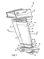
- FIG. 1 shows a vane 20 having an airfoil 22 extending from an inboard end at an inboard platform 24 to an outboard end at an outboard shroud 26.
- the airfoil 22 has a leading edge 28, a trailing edge 30, and pressure and suction side surfaces 32 and 34 extending between the leading and trailing edges.
- the exemplary platform and shroud form segments of an annulus so that a circumferential array of such vanes may be assembled with shrouds and platforms sealed/mated edge-to-edge.
- the exemplary vane 20 is an assembly wherein the shroud, platform, and airfoil are separately formed and then secured to each other.
- FIGS. 1-3 show the airfoil as comprising a thin-walled shell 50 and a structural spar 52 within the shell.
- Exemplary shell material is a CMC.
- the shell may be manufactured by various CMC fabrication methods. These typically involve forming a preform of ceramic fiber (e.g., SiC) in the shape of the airfoil (e.g., by weaving or other technique) and infiltrating the preform with matrix material (e.g., also SiC). Prior to infiltration, the preform may be coated for limiting bonding with the matrix (e.g., with BN by chemical vapor deposition (CVD)).
- SiC ceramic fiber
- matrix material e.g., also SiC
- Exemplary infiltration techniques include chemical vapor infiltration, slurry infiltration-sintering, polymer-impregnation-pyrolysis, slurry casting, and melt infiltration.
- Exemplary spar material is a metal alloy (e.g., a cast nickel-based superalloy).
- Inboard and outboard seals 53 and 54 respectively seal between inboard and outboard ends 55 and 56 of the shell and the adjacent platform and shroud.
- An outboard end portion 40 of the spar 52 may be mounted to the shroud 26.
- the portion 40 is received in an aperture in the shroud and welded thereto.
- a threaded stud 44 may be formed at the inboard end of the spar 52 and extend through an aperture in the platform 24.
- a nut 46 and washer(s) 47 may engage the stud and an inboard surface of the platform while a shoulder 48 of the spar bears up against a mating shoulder 49 of the platform.
- the spar may thus form the principal mechanical coupling between shroud and platform.
- the shell may be positioned relative to the spar by one or more of several mechanisms.
- the shell inboard and outboard ends 55 and 56 may be located by appropriate channels 57 in the platform and shroud, respectively. Additionally, spacers or seal/spacer units such as seals 53 and 54 may be positioned between the spar and the shell.
- the shell exterior surface 58 ( FIG. 2 ) defines the leading and trailing edges 28 and 30 and pressure and suction sides 32 and 34.
- the shell interior surface 60 includes a first portion along the pressure side and a second portion along the suction side. These define adjacent pressure and suction sidewall portions, which directly merge at the leading edge and merge more gradually toward the trailing edge.
- the spar 52 has an exterior surface 62 in close facing spaced-apart relation to the shell interior surface.
- the spar exterior surface has a leading edge 70, a trailing edge 72, and pressure and suction side portions 74 and 76.
- One or more seals may extend generally spanwise between the spar exterior surface 62 and shell interior surface 60.
- FIG. 3 further shows a streamwise direction 500 and a depth/thickness-wise direction 502 normal thereto.
- a spanwise direction 504 may extend normal to the cut plane of the view.
- the shell interior surface may be cooled.
- Exemplary cooling air may be delivered through one or more passageways 100 in the spar.
- the cooling air may be introduced to the passageways 100 via one or more ports in the shroud and/or platform.
- the cooling air may pass through apertures (not shown) in the shroud to one or more spaces 102 between the spar exterior surface and shell interior surface.
- the shell interior surface may typically be cooler than the adjacent shell exterior surface.
- the depth-wise temperature difference and thermal gradient may vary along the shell. Aerodynamic heating near the leading edge may make the difference and gradient particularly high near the leading edge.
- the shell is of uniform coefficient of thermal expansion (CTE)
- CTE uniform coefficient of thermal expansion
- a local temperature difference will cause an outboard/exterior portion of the shell to seek to expand more than an exterior/internal portion. This may cause an undesirable stress distribution.
- parallel to the surfaces tensile stresses may occur near the interior surface and compressive stresses near the exterior surface. This will also cause tensile stress normal to the surfaces and associated shear distributions.
- the relatively tight radius of curvature near the leading edge may exacerbate this problem.
- the stresses may be ameliorated by providing the shell with anisotropic thermal expansion properties at least along the leading edge region.
- the CTE may be greater in the direction normal to the shell interior and exterior surfaces than in the streamwise direction(s).
- the effect may be analogized to a hollow cylinder subject to a radial thermal gradient. If the radial CTE is increased above the circumferential CTE, this allows a relatively greater circumferential expansion of the exterior and thereby a reduction in stress.
- FIGS. 2 and 3 show a basic implementation wherein the shell is formed with two discrete regions 120 and 122.
- Region 120 is a leading edge region.
- the region 122 forms a remainder of the shell.
- the region 120 is of differing CTE properties than the region 122. In particular, the region 120 may have greater CTE anisotropy.
- FIG. 3 shows a local thickness T of the shell.
- the relative CTE properties of the regions 120 and 122 and the location of the boundary 124 ( FIG. 2 ) may be selected so as to minimize peak stresses (e.g., tensile stress) under anticipated conditions (e.g., normal operating conditions or an anticipated range of abnormal operating conditions).
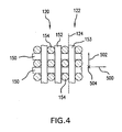
- FIG. 4 shows a first type of fiber 150 extending principally in the streamwise direction in the region 120 whereas a second type of fiber 152 extends principally in the depth/thickness-wise direction in the region 120 whereas a third type extends principally in the depth/thickness-wise direction in the region 122.
- the second fiber 152 may have a CTE greater than those of the first fiber 150 and third fiber.
- similar fibers may be used for the depth/thickness-wise direction as for the streamwise direction (e.g., fibers 153 in the depth/thickness-wise direction having properties similar to the fibers 150).
- the temperature gradient affects spanwise expansion, the lack of a tight spanwise radius of curvature means that the spanwise situation is not as significant.
- a single type of spanwise fiber 154 may be used throughout and may be similar to the fibers 150 and 153.
- the spanwise fibers 154 may be similar to the streamwise fibers.
- Alternative configurations may involve other fiber orientations ((e.g., the through thickness fiber is introduced via an angle lock weave).
- the region 120 extends a streamwise distance S 1 along the pressure side. This may be a portion of the total pressure side streamwise distance S p . Similarly, the region 120 extends a streamwise distance S 2 along the suction side which may be a portion of the total suction size streamwise distance S s .
- Exemplary S 1 is 5-20% of S p , more narrowly, 5-10%.
- Exemplary S 2 is 5-20% of S s , more narrowly, 5-10%.
- An exemplary characteristic depth/thickness-wise CTE of the region 120 is 5-20% of the characteristic thickness-wise CTE of the region 122, more narrowly, 5-10%.
- Exemplary local thickness of the region 120 is at least 50% of the total shell thickness T, more narrowly 75-100% or 80-99%.
- Table I below shows various properties of modified shells relative to baseline shells having uniform isotropic CTE.
- the plots were generated by finite element analysis software. Analysis utilized a baseline vane shape and a baseline operating condition (temperature gradient) for that baseline vane. Two representative shell thicknesses were used (0.05 inch (1.3mm) and 0.075 inch (2.0mm)).
- Example A utilized a depth-wise CTE of 10% less than the baseline while preserving CTE normal thereto.
- Example B utilized a depth-wise CTE of 10% more than the baseline.
- the example above includes an application where the stress free temperature for the baseline shell is below the actual use temperature. If the stress free temperature is above the actual use temperature, then the region 120 would have a lower CTE than the region 122.
- the anisotropic CTE may be implemented in the reengineering of a given vane.
- the reengineering may preserve the basic external profile of the shell.
- the reengineering may also preserve the internal profile.
- internal changes including local or general wall thinning may be particularly appropriate in view of the available stress reduction (e.g., a leading edge thinning at one or more locations along a leading tenth of the shell).
- the reengineering may also eliminate or reduce the size of other internal strengthening features such as tensile ribs/webs, locally thickened areas, and the like.
- the reengineering may overall or locally thin the shell (e.g., along a leading edge area such as a leading tenth).
- the reengineering may also more substantially alter the spar structure.
- the reengineered vane may be used in the remanufacturing of a given gas turbine engine.
Landscapes
- Engineering & Computer Science (AREA)
- Chemical & Material Sciences (AREA)
- Mechanical Engineering (AREA)
- General Engineering & Computer Science (AREA)
- Ceramic Engineering (AREA)
- Materials Engineering (AREA)
- Turbine Rotor Nozzle Sealing (AREA)
Applications Claiming Priority (1)
| Application Number | Priority Date | Filing Date | Title |
|---|---|---|---|
| US11/824,174 US8206098B2 (en) | 2007-06-28 | 2007-06-28 | Ceramic matrix composite turbine engine vane |
Publications (3)
| Publication Number | Publication Date |
|---|---|
| EP2009243A2 true EP2009243A2 (de) | 2008-12-31 |
| EP2009243A3 EP2009243A3 (de) | 2013-06-05 |
| EP2009243B1 EP2009243B1 (de) | 2014-07-16 |
Family
ID=39809889
Family Applications (1)
| Application Number | Title | Priority Date | Filing Date |
|---|---|---|---|
| EP08250435.8A Active EP2009243B1 (de) | 2007-06-28 | 2008-02-06 | Keramische Matrix-Verbund-Turbinenleitschaufel |
Country Status (2)
| Country | Link |
|---|---|
| US (1) | US8206098B2 (de) |
| EP (1) | EP2009243B1 (de) |
Cited By (2)
| Publication number | Priority date | Publication date | Assignee | Title |
|---|---|---|---|---|
| EP2781691A1 (de) | 2013-03-19 | 2014-09-24 | Alstom Technology Ltd | Verfahren zur Neukonditionierung für einen Heißgaspfad einer Gasturbine |
| EP3075963A1 (de) * | 2015-03-30 | 2016-10-05 | General Electric Company | Hybride düsensegmentanordnungen für einen gasturbinenmotor |
Families Citing this family (34)
| Publication number | Priority date | Publication date | Assignee | Title |
|---|---|---|---|---|
| US9080448B2 (en) * | 2009-12-29 | 2015-07-14 | Rolls-Royce North American Technologies, Inc. | Gas turbine engine vanes |
| US20110177318A1 (en) * | 2010-01-19 | 2011-07-21 | Kmetz Michael A | Ceramic composite article and method therefor |
| US9335051B2 (en) | 2011-07-13 | 2016-05-10 | United Technologies Corporation | Ceramic matrix composite combustor vane ring assembly |
| EP2943657B1 (de) | 2013-01-14 | 2019-08-14 | United Technologies Corporation | Strukturelle einlassleitschaufel aus organischem matrixverbund für einen turbinenmotor |
| EP2959110B1 (de) * | 2013-02-23 | 2017-06-28 | Rolls-Royce Corporation | Gasturbinenmotorkomponente |
| US10036264B2 (en) | 2013-06-14 | 2018-07-31 | United Technologies Corporation | Variable area gas turbine engine component having movable spar and shell |
| EP3047108B8 (de) | 2013-09-17 | 2021-03-31 | Raytheon Technologies Corporation | Tragflächenanordnung aus hochtemperaturbeständigem material |
| FR3021698B1 (fr) * | 2014-05-28 | 2021-07-02 | Snecma | Aube de turbine, comprenant un conduit central de refroidissement isole thermiquement de parois de l'aube par deux cavites laterales jointives en aval du conduit central |
| US10612401B2 (en) | 2014-09-09 | 2020-04-07 | Rolls-Royce Corporation | Piezoelectric damping rings |
| US9896954B2 (en) * | 2014-10-14 | 2018-02-20 | Rolls-Royce Corporation | Dual-walled ceramic matrix composite (CMC) component with integral cooling and method of making a CMC component with integral cooling |
| US10094239B2 (en) | 2014-10-31 | 2018-10-09 | Rolls-Royce North American Technologies Inc. | Vane assembly for a gas turbine engine |
| US9970317B2 (en) | 2014-10-31 | 2018-05-15 | Rolls-Royce North America Technologies Inc. | Vane assembly for a gas turbine engine |
| US10196910B2 (en) | 2015-01-30 | 2019-02-05 | Rolls-Royce Corporation | Turbine vane with load shield |
| US10060272B2 (en) | 2015-01-30 | 2018-08-28 | Rolls-Royce Corporation | Turbine vane with load shield |
| US10358939B2 (en) | 2015-03-11 | 2019-07-23 | Rolls-Royce Corporation | Turbine vane with heat shield |
| US10294809B2 (en) | 2016-03-09 | 2019-05-21 | Rolls-Royce North American Technologies Inc. | Gas turbine engine with compliant layer for turbine shroud mounts |
| US10207471B2 (en) * | 2016-05-04 | 2019-02-19 | General Electric Company | Perforated ceramic matrix composite ply, ceramic matrix composite article, and method for forming ceramic matrix composite article |
| US10436062B2 (en) * | 2016-11-17 | 2019-10-08 | United Technologies Corporation | Article having ceramic wall with flow turbulators |
| US10577978B2 (en) | 2016-11-30 | 2020-03-03 | Rolls-Royce North American Technologies Inc. | Turbine shroud assembly with anti-rotation features |
| EP3330497B1 (de) | 2016-11-30 | 2019-06-26 | Rolls-Royce Corporation | Turbinenummantelungsanordnung mit positionierungs-pads |
| US10767502B2 (en) * | 2016-12-23 | 2020-09-08 | Rolls-Royce Corporation | Composite turbine vane with three-dimensional fiber reinforcements |
| US10655491B2 (en) | 2017-02-22 | 2020-05-19 | Rolls-Royce Corporation | Turbine shroud ring for a gas turbine engine with radial retention features |
| US10724380B2 (en) * | 2017-08-07 | 2020-07-28 | General Electric Company | CMC blade with internal support |
| US10612399B2 (en) * | 2018-06-01 | 2020-04-07 | Rolls-Royce North American Technologies Inc. | Turbine vane assembly with ceramic matrix composite components |
| US10808560B2 (en) * | 2018-06-20 | 2020-10-20 | Rolls-Royce Corporation | Turbine vane assembly with ceramic matrix composite components |
| US10774665B2 (en) * | 2018-07-31 | 2020-09-15 | General Electric Company | Vertically oriented seal system for gas turbine vanes |
| US10605103B2 (en) | 2018-08-24 | 2020-03-31 | Rolls-Royce Corporation | CMC airfoil assembly |
| US10767497B2 (en) | 2018-09-07 | 2020-09-08 | Rolls-Royce Corporation | Turbine vane assembly with ceramic matrix composite components |
| US10934868B2 (en) | 2018-09-12 | 2021-03-02 | Rolls-Royce North American Technologies Inc. | Turbine vane assembly with variable position support |
| US10808553B2 (en) * | 2018-11-13 | 2020-10-20 | Rolls-Royce Plc | Inter-component seals for ceramic matrix composite turbine vane assemblies |
| US11047247B2 (en) * | 2018-12-21 | 2021-06-29 | Rolls-Royce Plc | Turbine section of a gas turbine engine with ceramic matrix composite vanes |
| US11365635B2 (en) * | 2019-05-17 | 2022-06-21 | Raytheon Technologies Corporation | CMC component with integral cooling channels and method of manufacture |
| US10883371B1 (en) * | 2019-06-21 | 2021-01-05 | Rolls-Royce Plc | Ceramic matrix composite vane with trailing edge radial cooling |
| US12535011B2 (en) | 2023-06-28 | 2026-01-27 | General Electric Company | High temperature gas turbine engine |
Citations (1)
| Publication number | Priority date | Publication date | Assignee | Title |
|---|---|---|---|---|
| US6514046B1 (en) | 2000-09-29 | 2003-02-04 | Siemens Westinghouse Power Corporation | Ceramic composite vane with metallic substructure |
Family Cites Families (15)
| Publication number | Priority date | Publication date | Assignee | Title |
|---|---|---|---|---|
| FR2195255A5 (de) * | 1972-08-04 | 1974-03-01 | Snecma | |
| US5356265A (en) | 1992-08-25 | 1994-10-18 | General Electric Company | Chordally bifurcated turbine blade |
| US5630700A (en) | 1996-04-26 | 1997-05-20 | General Electric Company | Floating vane turbine nozzle |
| US6280550B1 (en) * | 1998-12-15 | 2001-08-28 | General Electric Company | Fabrication of composite articles having an infiltrated matrix |
| US6283708B1 (en) | 1999-12-03 | 2001-09-04 | United Technologies Corporation | Coolable vane or blade for a turbomachine |
| US6464456B2 (en) | 2001-03-07 | 2002-10-15 | General Electric Company | Turbine vane assembly including a low ductility vane |
| US6709230B2 (en) | 2002-05-31 | 2004-03-23 | Siemens Westinghouse Power Corporation | Ceramic matrix composite gas turbine vane |
| US6648597B1 (en) | 2002-05-31 | 2003-11-18 | Siemens Westinghouse Power Corporation | Ceramic matrix composite turbine vane |
| US7093359B2 (en) | 2002-09-17 | 2006-08-22 | Siemens Westinghouse Power Corporation | Composite structure formed by CMC-on-insulation process |
| GB2402717B (en) | 2003-06-10 | 2006-05-10 | Rolls Royce Plc | A vane assembly for a gas turbine engine |
| US20050158171A1 (en) | 2004-01-15 | 2005-07-21 | General Electric Company | Hybrid ceramic matrix composite turbine blades for improved processibility and performance |
| US7223465B2 (en) * | 2004-12-29 | 2007-05-29 | General Electric Company | SiC/SiC composites incorporating uncoated fibers to improve interlaminar strength |
| US7258530B2 (en) * | 2005-01-21 | 2007-08-21 | Siemens Power Generation, Inc. | CMC component and method of fabrication |
| US7754126B2 (en) * | 2005-06-17 | 2010-07-13 | General Electric Company | Interlaminar tensile reinforcement of SiC/SiC CMC's using fugitive fibers |
| US7967570B2 (en) * | 2007-07-27 | 2011-06-28 | United Technologies Corporation | Low transient thermal stress turbine engine components |
-
2007
- 2007-06-28 US US11/824,174 patent/US8206098B2/en active Active
-
2008
- 2008-02-06 EP EP08250435.8A patent/EP2009243B1/de active Active
Patent Citations (1)
| Publication number | Priority date | Publication date | Assignee | Title |
|---|---|---|---|---|
| US6514046B1 (en) | 2000-09-29 | 2003-02-04 | Siemens Westinghouse Power Corporation | Ceramic composite vane with metallic substructure |
Cited By (7)
| Publication number | Priority date | Publication date | Assignee | Title |
|---|---|---|---|---|
| EP2781691A1 (de) | 2013-03-19 | 2014-09-24 | Alstom Technology Ltd | Verfahren zur Neukonditionierung für einen Heißgaspfad einer Gasturbine |
| US9926785B2 (en) | 2013-03-19 | 2018-03-27 | Ansaldo Energia Ip Uk Limited | Method for reconditioning a hot gas path part of a gas turbine |
| EP3075963A1 (de) * | 2015-03-30 | 2016-10-05 | General Electric Company | Hybride düsensegmentanordnungen für einen gasturbinenmotor |
| CN106014494A (zh) * | 2015-03-30 | 2016-10-12 | 通用电气公司 | 用于燃气涡轮发动机的混合喷嘴节段组件 |
| JP2016191379A (ja) * | 2015-03-30 | 2016-11-10 | ゼネラル・エレクトリック・カンパニイ | ガスタービンエンジン用のハイブリッドノズルセグメント組立体 |
| US9863260B2 (en) | 2015-03-30 | 2018-01-09 | General Electric Company | Hybrid nozzle segment assemblies for a gas turbine engine |
| CN106014494B (zh) * | 2015-03-30 | 2018-08-10 | 通用电气公司 | 用于燃气涡轮发动机的混合喷嘴节段组件 |
Also Published As
| Publication number | Publication date |
|---|---|
| EP2009243B1 (de) | 2014-07-16 |
| EP2009243A3 (de) | 2013-06-05 |
| US20090003993A1 (en) | 2009-01-01 |
| US8206098B2 (en) | 2012-06-26 |
Similar Documents
| Publication | Publication Date | Title |
|---|---|---|
| EP2009243B1 (de) | Keramische Matrix-Verbund-Turbinenleitschaufel | |
| EP2039884B1 (de) | Keramik-Matrix-Verbund-Turbinenleitschaufel | |
| US7452189B2 (en) | Ceramic matrix composite turbine engine vane | |
| US7435058B2 (en) | Ceramic matrix composite vane with chordwise stiffener | |
| US7563071B2 (en) | Pin-loaded mounting apparatus for a refractory component in a combustion turbine engine | |
| US8118546B2 (en) | Grid ceramic matrix composite structure for gas turbine shroud ring segment | |
| US7963745B1 (en) | Composite turbine blade | |
| US7950234B2 (en) | Ceramic matrix composite turbine engine components with unitary stiffening frame | |
| US9410437B2 (en) | Airfoil components containing ceramic-based materials and processes therefor | |
| EP2599959B1 (de) | Keramikmatrix-Verbundstrukturen einer Schaufel mit Verstärkungs- Hinterkante für Gasturbinenmotor | |
| US20070258809A1 (en) | Multi-layer ring seal | |
| CN103061827B (zh) | 一种混合型陶瓷基复合材料涡轮导向器叶片 | |
| US20040115395A1 (en) | Assembly containing a composite article and assembly method therefor | |
| US20060121265A1 (en) | Stacked laminate CMC turbine vane | |
| US20050169759A1 (en) | Gas turbine flowpath structure | |
| US20090324393A1 (en) | Ceramic matrix composite turbine engine component | |
| CA2571903A1 (en) | Composite blading member and method for making | |
| US10767494B2 (en) | CMC aerofoil | |
| EP3739175B1 (de) | Schaufel aus verbundwerkstoff mit keramikmatrix und stossverstärkungen | |
| WO2021034327A1 (en) | Three-dimensional ceramic matrix composite t-joint for airfoils via pin-weaving | |
| US12031455B2 (en) | Turbomachine turbine having CMC nozzle with load spreading | |
| CN103291370B (zh) | 涡轮机叶片 | |
| Prill et al. | Ceramic matrix composite turbine engine vane | |
| EP3822453B1 (de) | Schaufelblatt mit einer rippe mit wärmeleitungselement | |
| Schaff et al. | Ceramic matrix composite turbine engine vane |
Legal Events
| Date | Code | Title | Description |
|---|---|---|---|
| PUAI | Public reference made under article 153(3) epc to a published international application that has entered the european phase |
Free format text: ORIGINAL CODE: 0009012 |
|
| AK | Designated contracting states |
Kind code of ref document: A2 Designated state(s): AT BE BG CH CY CZ DE DK EE ES FI FR GB GR HR HU IE IS IT LI LT LU LV MC MT NL NO PL PT RO SE SI SK TR |
|
| AX | Request for extension of the european patent |
Extension state: AL BA MK RS |
|
| PUAL | Search report despatched |
Free format text: ORIGINAL CODE: 0009013 |
|
| AK | Designated contracting states |
Kind code of ref document: A3 Designated state(s): AT BE BG CH CY CZ DE DK EE ES FI FR GB GR HR HU IE IS IT LI LT LU LV MC MT NL NO PL PT RO SE SI SK TR |
|
| AX | Request for extension of the european patent |
Extension state: AL BA MK RS |
|
| RIC1 | Information provided on ipc code assigned before grant |
Ipc: F01D 5/28 20060101AFI20130426BHEP Ipc: F01D 9/04 20060101ALI20130426BHEP |
|
| 17P | Request for examination filed |
Effective date: 20131128 |
|
| RBV | Designated contracting states (corrected) |
Designated state(s): AT BE BG CH CY CZ DE DK EE ES FI FR GB GR HR HU IE IS IT LI LT LU LV MC MT NL NO PL PT RO SE SI SK TR |
|
| RIC1 | Information provided on ipc code assigned before grant |
Ipc: F01D 5/28 20060101AFI20131219BHEP Ipc: F01D 9/04 20060101ALI20131219BHEP |
|
| GRAP | Despatch of communication of intention to grant a patent |
Free format text: ORIGINAL CODE: EPIDOSNIGR1 |
|
| AKX | Designation fees paid |
Designated state(s): DE GB |
|
| INTG | Intention to grant announced |
Effective date: 20140128 |
|
| GRAS | Grant fee paid |
Free format text: ORIGINAL CODE: EPIDOSNIGR3 |
|
| GRAA | (expected) grant |
Free format text: ORIGINAL CODE: 0009210 |
|
| AK | Designated contracting states |
Kind code of ref document: B1 Designated state(s): DE GB |
|
| REG | Reference to a national code |
Ref country code: GB Ref legal event code: FG4D |
|
| REG | Reference to a national code |
Ref country code: DE Ref legal event code: R096 Ref document number: 602008033283 Country of ref document: DE Effective date: 20140828 |
|
| REG | Reference to a national code |
Ref country code: DE Ref legal event code: R097 Ref document number: 602008033283 Country of ref document: DE |
|
| PLBE | No opposition filed within time limit |
Free format text: ORIGINAL CODE: 0009261 |
|
| STAA | Information on the status of an ep patent application or granted ep patent |
Free format text: STATUS: NO OPPOSITION FILED WITHIN TIME LIMIT |
|
| 26N | No opposition filed |
Effective date: 20150417 |
|
| REG | Reference to a national code |
Ref country code: DE Ref legal event code: R082 Ref document number: 602008033283 Country of ref document: DE Representative=s name: SCHMITT-NILSON SCHRAUD WAIBEL WOHLFROM PATENTA, DE |
|
| REG | Reference to a national code |
Ref country code: DE Ref legal event code: R082 Ref document number: 602008033283 Country of ref document: DE Representative=s name: SCHMITT-NILSON SCHRAUD WAIBEL WOHLFROM PATENTA, DE Ref country code: DE Ref legal event code: R081 Ref document number: 602008033283 Country of ref document: DE Owner name: UNITED TECHNOLOGIES CORP. (N.D.GES.D. STAATES , US Free format text: FORMER OWNER: UNITED TECHNOLOGIES CORP., HARTFORD, CONN., US |
|
| REG | Reference to a national code |
Ref country code: DE Ref legal event code: R081 Ref document number: 602008033283 Country of ref document: DE Owner name: RAYTHEON TECHNOLOGIES CORPORATION (N.D.GES.D.S, US Free format text: FORMER OWNER: UNITED TECHNOLOGIES CORP. (N.D.GES.D. STAATES DELAWARE), FARMINGTON, CONN., US Ref country code: DE Ref legal event code: R081 Ref document number: 602008033283 Country of ref document: DE Owner name: RTX CORPORATION (N.D.GES.D. STAATES DELAWARE),, US Free format text: FORMER OWNER: UNITED TECHNOLOGIES CORP. (N.D.GES.D. STAATES DELAWARE), FARMINGTON, CONN., US |
|
| P01 | Opt-out of the competence of the unified patent court (upc) registered |
Effective date: 20230519 |
|
| REG | Reference to a national code |
Ref country code: DE Ref legal event code: R081 Ref document number: 602008033283 Country of ref document: DE Owner name: RTX CORPORATION (N.D.GES.D. STAATES DELAWARE),, US Free format text: FORMER OWNER: RAYTHEON TECHNOLOGIES CORPORATION (N.D.GES.D.STAATES DELAWARE), ARLINGTON, VA, US |
|
| PGFP | Annual fee paid to national office [announced via postgrant information from national office to epo] |
Ref country code: GB Payment date: 20260122 Year of fee payment: 19 |
|
| PGFP | Annual fee paid to national office [announced via postgrant information from national office to epo] |
Ref country code: DE Payment date: 20260121 Year of fee payment: 19 |