EP2009246A2 - Schaufelaufbau - Google Patents
Schaufelaufbau Download PDFInfo
- Publication number
- EP2009246A2 EP2009246A2 EP08251947A EP08251947A EP2009246A2 EP 2009246 A2 EP2009246 A2 EP 2009246A2 EP 08251947 A EP08251947 A EP 08251947A EP 08251947 A EP08251947 A EP 08251947A EP 2009246 A2 EP2009246 A2 EP 2009246A2
- Authority
- EP
- European Patent Office
- Prior art keywords
- blade
- mounting
- pitch
- counter
- root
- Prior art date
- Legal status (The legal status is an assumption and is not a legal conclusion. Google has not performed a legal analysis and makes no representation as to the accuracy of the status listed.)
- Withdrawn
Links
- 230000007246 mechanism Effects 0.000 claims abstract description 69
- 238000005096 rolling process Methods 0.000 claims description 32
- 230000002441 reversible effect Effects 0.000 claims description 15
- 238000004260 weight control Methods 0.000 abstract 1
- 238000009434 installation Methods 0.000 description 5
- 230000002829 reductive effect Effects 0.000 description 5
- 230000008901 benefit Effects 0.000 description 4
- 230000009471 action Effects 0.000 description 3
- 238000013461 design Methods 0.000 description 3
- 238000013459 approach Methods 0.000 description 2
- 230000001419 dependent effect Effects 0.000 description 2
- 230000000694 effects Effects 0.000 description 2
- 230000014759 maintenance of location Effects 0.000 description 2
- 230000000717 retained effect Effects 0.000 description 2
- 238000013519 translation Methods 0.000 description 2
- 230000000712 assembly Effects 0.000 description 1
- 238000000429 assembly Methods 0.000 description 1
- 238000006073 displacement reaction Methods 0.000 description 1
- 238000009826 distribution Methods 0.000 description 1
- 210000003746 feather Anatomy 0.000 description 1
- 239000012530 fluid Substances 0.000 description 1
- 238000013467 fragmentation Methods 0.000 description 1
- 238000006062 fragmentation reaction Methods 0.000 description 1
- 239000000446 fuel Substances 0.000 description 1
- 231100001261 hazardous Toxicity 0.000 description 1
- 230000000670 limiting effect Effects 0.000 description 1
- 239000010687 lubricating oil Substances 0.000 description 1
- 238000004519 manufacturing process Methods 0.000 description 1
- 238000000034 method Methods 0.000 description 1
- 238000012986 modification Methods 0.000 description 1
- 230000004048 modification Effects 0.000 description 1
- 239000002244 precipitate Substances 0.000 description 1
- 230000000750 progressive effect Effects 0.000 description 1
- 230000009467 reduction Effects 0.000 description 1
- 230000000452 restraining effect Effects 0.000 description 1
Images




Classifications
-
- F—MECHANICAL ENGINEERING; LIGHTING; HEATING; WEAPONS; BLASTING
- F01—MACHINES OR ENGINES IN GENERAL; ENGINE PLANTS IN GENERAL; STEAM ENGINES
- F01D—NON-POSITIVE DISPLACEMENT MACHINES OR ENGINES, e.g. STEAM TURBINES
- F01D7/00—Rotors with blades adjustable in operation; Control thereof
- F01D7/02—Rotors with blades adjustable in operation; Control thereof having adjustment responsive to speed
-
- B—PERFORMING OPERATIONS; TRANSPORTING
- B64—AIRCRAFT; AVIATION; COSMONAUTICS
- B64C—AEROPLANES; HELICOPTERS
- B64C11/00—Propellers, e.g. of ducted type; Features common to propellers and rotors for rotorcraft
- B64C11/02—Hub construction
- B64C11/04—Blade mountings
- B64C11/06—Blade mountings for variable-pitch blades
-
- F—MECHANICAL ENGINEERING; LIGHTING; HEATING; WEAPONS; BLASTING
- F01—MACHINES OR ENGINES IN GENERAL; ENGINE PLANTS IN GENERAL; STEAM ENGINES
- F01D—NON-POSITIVE DISPLACEMENT MACHINES OR ENGINES, e.g. STEAM TURBINES
- F01D21/00—Shutting-down of machines or engines, e.g. in emergency; Regulating, controlling, or safety means not otherwise provided for
- F01D21/14—Shutting-down of machines or engines, e.g. in emergency; Regulating, controlling, or safety means not otherwise provided for responsive to other specific conditions
-
- F—MECHANICAL ENGINEERING; LIGHTING; HEATING; WEAPONS; BLASTING
- F01—MACHINES OR ENGINES IN GENERAL; ENGINE PLANTS IN GENERAL; STEAM ENGINES
- F01D—NON-POSITIVE DISPLACEMENT MACHINES OR ENGINES, e.g. STEAM TURBINES
- F01D5/00—Blades; Blade-carrying members; Heating, heat-insulating, cooling or antivibration means on the blades or the members
- F01D5/30—Fixing blades to rotors; Blade roots ; Blade spacers
-
- F—MECHANICAL ENGINEERING; LIGHTING; HEATING; WEAPONS; BLASTING
- F05—INDEXING SCHEMES RELATING TO ENGINES OR PUMPS IN VARIOUS SUBCLASSES OF CLASSES F01-F04
- F05D—INDEXING SCHEME FOR ASPECTS RELATING TO NON-POSITIVE-DISPLACEMENT MACHINES OR ENGINES, GAS-TURBINES OR JET-PROPULSION PLANTS
- F05D2220/00—Application
- F05D2220/30—Application in turbines
- F05D2220/32—Application in turbines in gas turbines
- F05D2220/324—Application in turbines in gas turbines to drive unshrouded, low solidity propeller
-
- F—MECHANICAL ENGINEERING; LIGHTING; HEATING; WEAPONS; BLASTING
- F05—INDEXING SCHEMES RELATING TO ENGINES OR PUMPS IN VARIOUS SUBCLASSES OF CLASSES F01-F04
- F05D—INDEXING SCHEME FOR ASPECTS RELATING TO NON-POSITIVE-DISPLACEMENT MACHINES OR ENGINES, GAS-TURBINES OR JET-PROPULSION PLANTS
- F05D2220/00—Application
- F05D2220/30—Application in turbines
- F05D2220/32—Application in turbines in gas turbines
- F05D2220/326—Application in turbines in gas turbines to drive shrouded, low solidity propeller
-
- F—MECHANICAL ENGINEERING; LIGHTING; HEATING; WEAPONS; BLASTING
- F05—INDEXING SCHEMES RELATING TO ENGINES OR PUMPS IN VARIOUS SUBCLASSES OF CLASSES F01-F04
- F05D—INDEXING SCHEME FOR ASPECTS RELATING TO NON-POSITIVE-DISPLACEMENT MACHINES OR ENGINES, GAS-TURBINES OR JET-PROPULSION PLANTS
- F05D2250/00—Geometry
- F05D2250/20—Three-dimensional
- F05D2250/25—Three-dimensional helical
-
- F—MECHANICAL ENGINEERING; LIGHTING; HEATING; WEAPONS; BLASTING
- F05—INDEXING SCHEMES RELATING TO ENGINES OR PUMPS IN VARIOUS SUBCLASSES OF CLASSES F01-F04
- F05D—INDEXING SCHEME FOR ASPECTS RELATING TO NON-POSITIVE-DISPLACEMENT MACHINES OR ENGINES, GAS-TURBINES OR JET-PROPULSION PLANTS
- F05D2260/00—Function
- F05D2260/70—Adjusting of angle of incidence or attack of rotating blades
- F05D2260/77—Adjusting of angle of incidence or attack of rotating blades the adjusting mechanism driven or triggered by centrifugal forces
-
- F—MECHANICAL ENGINEERING; LIGHTING; HEATING; WEAPONS; BLASTING
- F05—INDEXING SCHEMES RELATING TO ENGINES OR PUMPS IN VARIOUS SUBCLASSES OF CLASSES F01-F04
- F05D—INDEXING SCHEME FOR ASPECTS RELATING TO NON-POSITIVE-DISPLACEMENT MACHINES OR ENGINES, GAS-TURBINES OR JET-PROPULSION PLANTS
- F05D2260/00—Function
- F05D2260/70—Adjusting of angle of incidence or attack of rotating blades
- F05D2260/79—Bearing, support or actuation arrangements therefor
-
- Y—GENERAL TAGGING OF NEW TECHNOLOGICAL DEVELOPMENTS; GENERAL TAGGING OF CROSS-SECTIONAL TECHNOLOGIES SPANNING OVER SEVERAL SECTIONS OF THE IPC; TECHNICAL SUBJECTS COVERED BY FORMER USPC CROSS-REFERENCE ART COLLECTIONS [XRACs] AND DIGESTS
- Y02—TECHNOLOGIES OR APPLICATIONS FOR MITIGATION OR ADAPTATION AGAINST CLIMATE CHANGE
- Y02T—CLIMATE CHANGE MITIGATION TECHNOLOGIES RELATED TO TRANSPORTATION
- Y02T50/00—Aeronautics or air transport
- Y02T50/60—Efficient propulsion technologies, e.g. for aircraft
Definitions
- the present invention relates to blade mountings and more particularly blade mountings utilised in turboprop or propfan engines for aircraft propulsion.
- Turboprop and propfan engines utilise low pressure turbines to drive a large propeller through a speed reduction mechanism such as a gearbox or by an interleaved turbine configuration. For a given engine weight with a large propeller such engines accelerate more air than a turbofan engine and so delivers more thrust for a given engine in terms of fuel consumption. There are other advantages in that turboprops are generally lighter and have advantages particularly at lower flight speeds.
- variable pitch allows optimisation of aerodynamic performance for engine speed within an operational performance envelope for the engine.
- the pitch of the propeller is controlled typically through mechanical or hydraulic mechanisms. These variable pitch mechanisms clearly are subject to potential failure during operation. If the variable pitch mechanism should fail it will be understood that there is a natural tendency for the blades to turn towards a flat fine or cross-wise pitch configuration where the blade is substantially flat due to the centrifugal or turning moment created by the propeller aerofoil shape. Such turning towards a flatter pitch orientation produces less drag resistance in the direction of rotation such that a blade in a flat pitch requires little torque compared to when in operating pitch positions for thrust.
- variable pitch mechanism failure of the variable pitch mechanism can lead to the power turbine and propeller rotor over-speeding.
- over-speeding there is the potential for further failure of the rotating members as well as possible fragmentation of the blades and other parts leading to distribution of high energy debris about the engine.
- variable pitch blade rotors such as described in US Patent 4717312 utilise a ball screw mechanism in order to provide pitch rotation.
- the ball screw mechanism includes an inner and outer screw trace respectively having a helical groove formed therein along which rotating elements which travel in order to provide pitch rotation.
- a rotatable driving centrifugal cage is disposed between the inner and outer races with longitudinal slots in which a plurality of rolling element balls is positioned. The balls are located in the slots and are moveable longitudinally, which prevents ball bunching as a result of centrifugal forces.
- a drive mechanism is utilised with respect to the cage in order to drive the cage for a blade pitch movement. The cage as indicated prevents ball crowding through the centrifugal forces.
- the screw path will provide coarse pitch seeking turning moments to aid the pitch variation mechanism when turning towards such coarse pitch configurations whilst avoiding the problems with rolling elements bunching during normal operation which may lead to blade instability.
- Limitations upon pitch angle and roller element sizes must be applied or as outlined in US Patent 4717312 provision provided in the form of a cage for restraining rolling element movement and therefore limitation upon coarse pitch moments provided.
- US Patent 4948339 It is also known from US Patent 4948339 to provide a fail safe mechanism for an aircraft propeller.
- the mechanism comprises a first bearing trace which is angular about a blade shank and having two or more surfaces which are generally helical about the axis.
- the second, generally helical, bearing trace is fastened to the shank but which is not parallel to the first bearing trace.
- a plurality of bearing rollers is located between the first and second bearing traces. In such circumstances, a displacing force is generated due to the lack of parallelism between the first and second bearing traces. Thus, will allow some coarse pitch rotation to be provided, but there is a limited in angular rotation achievable.
- a blade mounting to secure a blade or rotor within a hub, the mounting having a root extending into the hub, the mounting characterised by a helix trace associated with the blade root to define a helix path between them about an axis, a rolling element is captured in the helix path allowing rotation of the blade root about the axis and the helix path having a helix angle orientated and matched to the rolling element to ensure such rotation to turn the blade root in a counter direction about the axis and when subject to an expected or predetermined radial force.
- the rolling element defines a bearing in the helix path.
- the helix angle is arranged to radially displace and provide a counter moment to the turning moment.
- the helix angle is up to ten degrees and preferably about three degrees across the axis.
- blade mounting incorporates at least one stop lock to define a range for rotation of the blade.
- the stop lock is deployable.
- the stop lock is positioned to limit the rotation of the blade to any one or more of maximum thrust, cruise thrust, fine, brake, reverse, flat or feathered pitch.
- a plurality of stop locks is provided to provide angular position the blade for a number of defined engine operating conditions.
- the blade root is associated with a pitch control mechanism to selectively turn the blade root in use.
- the mounting includes a counterweight associated with the root to act in association with the rolling element in the helix path to turn the blade root in the counter direction.
- the engine is a turboprop or propfan engine utilised for aircraft propulsion.
- the engine is a turbofan with variable pitch blades within a casing; the casing is trenched opposite tips of the blades.
- variable pitch blades are particularly advantageous.
- the hydraulic or mechanical mechanism utilised for achieving such variable pitch may fail leading to hazardous conditions with regard to excessive rotation speeds and possibly high energy debris release.
- a fail safe system must be provided.
- These fail safe systems can lock the pitch of the blade or utilise counter weights to force turning to a feathering blade pitch. Pitch locking mechanisms are complicated and result in the blade retaining a set high forward drag configuration whilst counter balance systems have a significant weight penalty generally undesirable with regard to aircraft propulsion.
- FIG. 1 provides a schematic illustration of a cross section of a typical engine configuration in which a blade mounting arrangement in accordance with aspects of the present invention will be utilised.
- the engine configuration 1 incorporates a gas turbine engine including compressor and turbine stages in order that a shaft 2 can drive sets of blades 5, 6 through gearboxes 3, 4.
- An alternative variable blade pitch engine includes configurations where the propeller or fan is driven by an interleaved turbine and not a gear box. Aspects of the present invention relate to any variable pitch blade engine where failure of the variable pitch mechanism may lead to run away. As indicated above it is these blades 5, 6 which provide propulsion in a way which is more efficient particularly at lower speeds than a jet engine.
- variable pitch provided through blade mountings 7, 8 and in particular variable pitch mechanisms located within these mounting 7, 8. It is when these variable pitch mechanisms fail that the blades 5, 6 can then turn as a result of centrifugal radial forces as the blades rotate to the orientation of less resistance and drag. This radial force is schematically illustrated in the direction of arrowheads A in figure 1 .
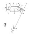
- FIG. 2 provides a schematic illustration of the forces and turning moments presented to a blade 20 having a variable pitch mounting.
- the blade 20 is secured to a hub (not shown) which in turn rotates about an axis X-X in an engine configuration.
- the direction of rotation is shown by arrowhead 21.
- the blade 21 within an engine will provide propulsion in the direction of arrowhead 22 and therefore there will be airflow in the opposite direction.
- the blade 20 will be secured upon a pitch variation mechanism and robustly held in the desired pitch configuration such that the aerofoil nature of the blade 20 generates thrust in a most efficient manner.
- Aspects of the present invention relate to situations when the variable pitch mechanism fails.
- the blade 21 is rapidly rotated about the axis X-X and therefore there is a significant radial centrifugal force 23.
- the radial force in association with the aerofoil configuration of the blade 20 causes a centrifugal turning moment (CTM) which tends to turn the blade 20 in the direction of arrowheads 24 into a flat pitch shown by broken lines 25.
- CTM centrifugal turning moment
- the aerofoil also has an aerodynamic turning moment (ATM) 90 which partly counteracts the CTM and is typically about 25% of the CTM. This invention therefore seeks to fully counteract the dominant CTM.
- a counter turning moment is generated by a combination of the mass of the blade 20 and the radial outward translation due to radial centrifugal force 23.
- This counter turning moment generates rotation in a counter direction illustrated by arrowhead 26.
- the opposing turning moments 24 (CTM), 26 helix counter turning moment
- This relationship is illustrated later with regard to figure 9 .
- a degree of drag is maintained by the blade 20 and therefore excessive speed is avoided.
- the counter turning moment 26 would be set to be always greater than the CTM 24 for all expected conditions to ensure "safe" feathering of the blade 20.
- a helix bearing is provided by a helix pitch in which a rolling element combination is captured.
- the helix path in terms of its orientation, dimensions and in particular its helix angle are matched with acceptable rolling element sizes for the installation to ensure the value of the counter turning moment with the available radial force due to blade mass as well as rotational speed is sufficient.
- a plurality of blades 20 will be located upon appropriate blade mountings about a circumference 28 and the axis X-X.
- This circumference 28 will normally be provided by a hub (not shown) and the axis X-X defined by a rotating shaft upon which the hub providing the circumference 28 is located. In such circumstances 28 each blade will provide a component of an overall drag coefficient limiting rotational speed.
- aspects of the present invention provide a blade mounting so that the mass of the blade as well as the radial centrifugal force generate a turning moment in a counter direction to the natural centrifugal turning moment (CTM) of each blade.
- the blade mounting incorporates a helix bearing.
- Figure 3 provides a schematic cross section of a blade mounting in accordance with aspects of the present invention. The counter moment to turn the blade in a counter direction to the CTM is achieved through the blade unscrewing against the helical bearing.
- a blade 31 is associated with a blade root 32 in which a helical bearing arrangement is provided in order to create a counter moment as indicated using the mass of the blade 31 and a radial translation generated through centrifugal action.
- the blade root 32 is located within a hub or disc 33 and in particular an aperture 34 incorporating a helix trace 35.
- the helix trace 35 is in a groove worked into the aperture 34.
- a surface of the blade root 32 and the helix trace 35 define a helix path within which roller elements 36 are located. Only one roller element 36 is illustrated in figure 3 for clarity but it will be appreciated that such elements 36 extend generally completely about the helix path defined between the root 32 and the helix trace 35.
- the roller elements 36 are generally balls which act within the helix path to define the helical bearing to present the root 32 and therefore the blade 31 in use.
- the trace 35 may be in the aperture 35 but alternatively a helix trace may be provided in the root 32 or preferably both to define the helix path. If the helix trace is only provided to one side of the helix path then the roller elements need to be constrained in a cage or otherwise in order to provide the turning action in accordance with aspects of the present invention. The cage or constraint will be secured to the root or aperture wall as required.
- the extent of the helix path is defined by the lock stops 37, 38 positioned within the aperture 34.
- the roller elements 36 are generally loaded into a retaining cage 39 to retain position and precipitate such screw assembly of the root 32 into the hub or disc 33.
- a locking plate 30 Once in position a locking plate 30 will generally be located in order to position the stop lock 38. In such circumstances the blade 31 upon the root 32 can turn along and in a counter direction range defined between the locks stops 37, 38.
- a pitch control mechanism 40 is provided to enable adjustment of the blade 31 orientation and pitch in normal operational use.
- the mechanism 40 generally comprises a shaft schematically illustrated as secured to a base part of the root 32 to enable turning in the direction of arrowheads 41 and so adjust the orientation of the blade 31.
- the pitch control mechanism will robustly present and hold the blade 31 in the desired pitch. It is when the pitch control mechanism fails and therefore such robust presentation is no longer provided that aspects of the present invention are utilised in order to prevent over-speeding.
- a blade root 32 supported simply upon a failed pitch control mechanism can turn about the mounting shaft of that mechanism such that the blade may turn into a flat low rotational drag configuration enabling the engine to over-speed.
- the radial force generated by turning of the hub or disc 33 is utilised in combination with the mass of the blade to drive a counter moment maintaining at least some coarse aspect to the blade orientation for drag resistance and so limit rotational speed.
- the blade root and therefore the blade can turn relatively freely in the direction of arrowheads 41 about an axis Y-Y. Without some form of restraint, whether that be a pitch locking mechanism or a counter weight mechanism, the blade will turn to the configuration of least resistance, that is to say flat with limited, if any, drag.
- a counter moment is created to turn the root 32 and therefore the blade 31 in the counter direction to that expected for least resistance with the aerofoil configuration of the blade 31. It will be appreciated that it is the helix angle 42 which generates the counter moment and therefore the angle chosen will depend upon desired operational performance.
- the nature of a helical bearing means that the centrifugal force is pulling the blade radially outwards in the direction of arrowhead 43 which causes the blade to rotate.
- the outward radial force in accordance with aspects of the present invention is utilised to generate the counter moment.
- the helix angle 42 is chosen and adjusted to give the required turning moment to counter the normal aerofoil centrifugal turning moment (CTM) as a bias towards the flat configuration.
- the counter moment will be chosen to be greater than and normally a multiple of the natural aerofoil centrifugal turning moment (CTM). It will be understood that the counter moment and the centrifugal turning moment (CTM) will effectively be balanced to retain the coarser blade configuration. Thus, the counter moment must exceed the aerofoil centrifugal turning moment (CTM) to leave the blade towed into a coarser configuration to maintain a drag level necessary to limit rotational speed.
- CTM aerofoil centrifugal turning moment
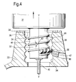
- Figure 5 illustrates a rolling element 36 located within the cage 39 in order to maintain position in the blade mounting in accordance with aspects of the present invention.
- a cage 39 is necessary to control location of the rolling element 36 relative to the root 32 and aperture 34 of the hub or disc 33.
- a cage 39 is particular necessary as described above if the root 32 does not include a reciprocal helical trace 44 or vice versa for ease of manufacture or assembly.
- a helix path 45 is defined for the rolling elements 36 in the space between the helix trace and the blade root.
- the rolling elements 36 utilise the incline provided by the helix angle 42 to generate the counter moment to turn the blade 31 when subject to radial force 33 due to centrifugal effects.
- Figure 6 is a section at A-A taken from figure 5 showing the engagement between the cage 39 and race 32 thereby holding the elements 36 in place to prevent crowding.
- the cage 39 also enables assembly and disassembly of the bearing.
- the crowded rolling elements act to maximise the number of elements within a given radial span and thereby reduce the CF induced load reacted by a single element.
- the rotational or turning range is defined between the stops 37, 38.
- the position of the stops 37, 38 will be to leave the blade 43 turned towards a coarser configuration sometimes referred to as a forward-aft or feathering configuration for the blade 31.
- the stops 37, 38 are located within the hub or disc 33 and as will be illustrated below with regard to figure 5 effectively decide the acceptable range of orientations in pitch control mechanism failure conditions.
- the locking plate 30 will be removed to enable the blade and in particular the root 32 to be screwed into position within the aperture 34 along the roller elements 36.
- the pitch control mechanism 40 will be associated with the root 32 and the locking plate 30 located in order to provide the lock stop 38 to define the range for the roller elements 36 in the cage 39.
- the extent of blade pitch rotation in normal use is not limited to between the stops 37, 38.
- the root 32 can simply be turned by the mechanism and the rolling elements 26 of the helical beam. Engagement with the rolling elements 36 retains the root 32 and therefore the blade 31 in position relative to the hub or disc 33. In such circumstances in normal operation adjustment of the blade 32 is achieved as previously through the pitch control mechanism 40.
- the counter moment as well as the natural CTM of the blade is governed by the retention of the root 32 upon the pitch control mechanism. If the control mechanism fails then the opposed counter moment and natural CTM act within the range defined by the stops 37, 38.
- this angle 42 generally allows turning of the blade 31 by providing a means of utilising the radial force and mass of the blade 31 to drive turning. This turning will result in a slight outward movement of the blade 31 also in the direction of the radial force 43.
- turboprop arrangement it will be appreciated that the blades 31 are not constrained within a casing and such movement will be acceptable. If the blades 31 are within a casing further consideration with regard to the helix angle 42 must be made such that a balance is struck between achieving an appropriate value for the counter moment as a result of the angle 42 and the potential outwards displacement of the blade 31 causing clash with a casing.
- Figure 6 illustrates an alternative arrangement where the helical cage is removed and replaced by a simple "crowded" bearing 56.
- Figure 6 illustrates the crowded bearing arrangement. This enables an increased number of elements 56 to reduce individual element load. This arrangement is particularly advantageous in cases of small helix angle 4Z (approximately 1 degree) where the rolling element size is likely to be reduced.
- Loading of the elements into the helical track 44, following location of the blade 31 within the hub 33, is through a loading hole 46. Once, the elements are loaded, they are secured in the helical path by a secured, but removable plug 47. In this arrangement the turning of the blade 31 about axis Y-Y is restricted by the stop locks 38 secured to the hub and stop lock 48 secured to the blade hub 32.
- the casing itself may include trenching, that is to say a groove in the casing in which tips of the blades are located. Such trenching may be to limit leakage but in accordance with aspects of the present invention will also provide a depth into which radially displaced blades in accordance with aspects of the present invention as a result of movement on the helical bearing can be accommodated.
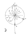
- FIG. 7 provides a schematic plan view of blade configurations in accordance with aspects of the present invention.
- a blade 51 in accordance with aspects of the present invention is limited to a pitch range from a fine pitch defined by blade 51a to a coarse pitch defined by blade 51b.
- the blade rotation is in the direction of arrowhead 21 and in the event of pitch control failure the preferred movement under centrifugal forces is towards "feather", that is to say the blade moves towards the perpendicular to the direction of rotation shown by broken line 51c.
- the blade 51 is located upon a blade mounting in accordance with aspects of the present invention which incorporates a helical bearing.
- the blade 51 can be rotated about an axis 52 to a desired pitch using a pitch control mechanism (not shown). If the pitch control mechanism fails then as indicated without a safety mechanism or a blade mounting in accordance with aspects of the present invention the blade 51 will move to a fine pitch configuration 51a or even a flat pitch configuration aligned with an axis Y-Y.
- Such a fine or flat configuration as indicated previously has limited rotational drag and therefore potential for over-speeding within an engine driving blade rotation.
- stops 37, 38 are used to engage the rolling elements in the cage 39 and/or for blade root 32.
- the rolling elements 36 will engage a bottom stop 37 in one pitch orientation and a top stop 38 in another pitch configuration between configurations of blades 51a, 51b.
- the stops 37, 38 are arranged on the blade root 32 and hub 33 to limit the range of turning of the root 32 and therefore configurations for the blade 51 (shown as blade 31 in figure 3 ).
- the blades 51 in accordance with aspects of the present invention may be turned by the pitch variation mechanism to a brake or reverse pitch configuration illustrated by broken lines 51d, 51e.
- These blade configurations allow reverse thrust and as will be described later require movement across the fine or flat pitch configuration. Nevertheless, the period of time in the flat or fine pitch configurations is limited and therefore over speeding of the engine is minimal.
- the range will be between the configurations shown by broken lines 51d, 51e which continue to provide some rotational drag and therefore limit engine over speeding.
- the blades in such circumstances will have a pitch angle 55 in the range 20 to 60 degrees from a flat configuration defined by axis Y-Y.
- the helix angle 42 and other aspects of the blade arrangement will normally be chosen such that the counter moment generated by the helical bearing exceeds the CTM.
- the stop 37, 38 prevents the blade moving to a position to fully relieve the CTM and so maintains desirable drag for speed limitation. Operating ranges for the blades can be defined such that there is no excessive stressing to the blade 31.
- the blade mounting in accordance with aspects of the present invention utilises centrifugal force as well as blade mass in order to generate the counter moment for turning.
- the radial force to cause such turning and counter moment will only be applied for a split second during the transit through the flat configuration and therefore in normal operation the rolling elements will not engage the stops 37, 38 unless the pitch control mechanism fails.
- the pitch control mechanism restrains both the centrifugal turning moment caused by the aerofoil of the blade as well as the counter moment generated in accordance with aspects of the present invention through the helical path.
- brake or reverse pitch is typically achieved by turning through flat pitch.
- brake or reverse pitch is typically achieved by turning through flat pitch.
- Figure 8 illustrates an alternative mode of operation where by virtue of a continuous helical track on the blade and hub turning about the blade axis can be up to 360 degrees.
- This allows reverse pitch 51d to be achieved by turning in an anti-clockwise direction 61 or a clockwise direction 62.
- the clockwise direction 62 avoids normal operation through the undesirable flat pitch position.
- the blade would need to continue to turn through direction 63 to achieve a safe position 51a perpendicular to the engine rotation driven by the counter turning moment forcing the blade in the clockwise direction.
- the hub mounted stop lock 38 would need to be positioned appropriately to engage the hub through stop lock 37 or 48 and ensure the blade come to rest in the safe position 51c.
- deployable locks 37a and 37b may be used to avoid inadvertent thrust reverse. This will enable an extended rotation range of the blade where by reverse or brake pitch can be achieved by either clockwise or anti-clockwise rotation and still achieve a "safe" position perpendicular to the direction of rotation in event of pitch control failure.
- the deployable locks 37a and 37b are positioned at the extremities of desired pitch rotation; however, one or more additional deployable locks 37c may be positioned between locks 37a and 37b. As shown in figure 8 deployable lock 37c is positioned to prevent rotation beyond fine pitch. In other embodiments, the stop lock may be positioned to limit the rotation of the blade to any of maximum thrust, cruise thrust, brake, reverse, flat or feathered pitch. As will be appreciated a plurality of stop locks may be provided to provide angular position the blade for a number of defined engine operating conditions.
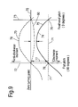
- FIG. 9 provides a graphic representation of the centrifugal turning moment (CTM) 70 and the counter turning moment 71 due to unscrewing about the helical bearing due to the mass of the blade and centrifugal force upon rolling elements.
- the centrifugal turning moment 70 (defined as 24 in figure 2 ) defines a curve between a flat pitch 72 and a feathered pitch 73.
- Curve 74 illustrates the resultant moment between the centrifugal turning moment 70, the ATM 90 and the counter turning moment 71 as a result of the helical bearing in accordance with aspects of the present invention.
- line 76 is considered as a zero turning moment then the counter turning moment 71 acts to displace the effective base line of the CTM by a factor illustrated by point 76 on the ordinate defining turning moment in an anti-clockwise and a clockwise direction. This point 76 is displaced below the zero moment 75 by a value 77.
- the value 77 is greater than the maximum turning moment (CTM) defines at 45 degrees and shown on curve 70 about position 78 it will be understood that the resultant curve 75 will never reach the zero turning moment and therefore there will always be an anti-clockwise moment as a result of the helical bearing action upon the blade. This anti-clockwise moment will act always to turn the blade into a position where there is some rotational drag and therefore prevent rotational speed run away.
- CTM maximum turning moment
- Figure 9 depicts a constant tip or blade speed, however, it should be understood that the curves will be more complex with varying speed caused by varying the propeller pitch.
- aspects of the present invention provide for a counter turning moment without the need for a counter weight mechanism.
- counter weight mechanisms which rotates with the blade and mounting, have particular disadvantages in terms of their weight penalty in aircraft installations.
- aspects of the present invention through provision of a helical bearing provides a counter turning moment it will be appreciated that a reduced mass for the counter weight may be used if a mounting arrangement in accordance with aspects of the present invention is combined with a counter weight mechanism. In such circumstances greater design freedom may be achieved by combining a prior counter weight mechanism with the present helical bearing mechanism.
- the present helical bearing mounting arrangement depends upon the helix angle and rolling element dimensions to achieve the counter turning moment.
- a much reduced counter weight mechanism may be combined with a mounting in accordance with aspects of the present invention such that the combination achieves necessary functional effect with regard to a failed pitch variation mechanism but without excessive weight penalties as a result of the counter weight mechanism or presenting difficulties with respect to achieving counter turning moments with a helical bearing in accordance with aspects of the present invention.
- the counter weight mechanism would be positioned as shown in figure 2 .
- a counter weight 80 would be located on a moment arm 81 and operated in order to limit rotational speed by generating a counter moment turning of the blade 20.
- the stops may be simply latch surfaces or comprise wedge engagements with the rolling elements such that there is progressive restraint dependent upon the forces applied.
- the rolling elements 36 may be open or retained within a closed vessel with a lubricating oil acting to facilitate the rotation and/or providing dampening fluid flow restraint past the rolling elements 36 in rotation one way or the other.
Landscapes
- Engineering & Computer Science (AREA)
- Mechanical Engineering (AREA)
- General Engineering & Computer Science (AREA)
- Aviation & Aerospace Engineering (AREA)
- Structures Of Non-Positive Displacement Pumps (AREA)
Applications Claiming Priority (1)
| Application Number | Priority Date | Filing Date | Title |
|---|---|---|---|
| GBGB0712561.0A GB0712561D0 (en) | 2007-06-28 | 2007-06-28 | A blade mounting |
Publications (2)
| Publication Number | Publication Date |
|---|---|
| EP2009246A2 true EP2009246A2 (de) | 2008-12-31 |
| EP2009246A3 EP2009246A3 (de) | 2012-12-05 |
Family
ID=38420874
Family Applications (1)
| Application Number | Title | Priority Date | Filing Date |
|---|---|---|---|
| EP08251947A Withdrawn EP2009246A3 (de) | 2007-06-28 | 2008-06-04 | Schaufelaufbau |
Country Status (3)
| Country | Link |
|---|---|
| US (1) | US20090004008A1 (de) |
| EP (1) | EP2009246A3 (de) |
| GB (1) | GB0712561D0 (de) |
Cited By (9)
| Publication number | Priority date | Publication date | Assignee | Title |
|---|---|---|---|---|
| EP2368795A2 (de) | 2010-03-09 | 2011-09-28 | Rolls-Royce plc | Propelleranordnung |
| US9145776B2 (en) | 2011-06-14 | 2015-09-29 | Rolls-Royce Plc | Retention device for a rotating blade |
| EP3023591A1 (de) * | 2014-11-21 | 2016-05-25 | General Electric Company | Gebläse mit verstellbarer neigung für gasturbinenmotor und verfahren zur montage davon |
| WO2017118820A1 (fr) * | 2016-01-05 | 2017-07-13 | Safran Aircraft Engines | Soufflante à calage variable à faible pas d'une turbomachine |
| US9869190B2 (en) | 2014-05-30 | 2018-01-16 | General Electric Company | Variable-pitch rotor with remote counterweights |
| US10100653B2 (en) | 2015-10-08 | 2018-10-16 | General Electric Company | Variable pitch fan blade retention system |
| US11674435B2 (en) | 2021-06-29 | 2023-06-13 | General Electric Company | Levered counterweight feathering system |
| US11795964B2 (en) | 2021-07-16 | 2023-10-24 | General Electric Company | Levered counterweight feathering system |
| US12601271B2 (en) | 2022-10-21 | 2026-04-14 | General Electric Company | Variable pitch fan of a gas turbine engine |
Families Citing this family (11)
| Publication number | Priority date | Publication date | Assignee | Title |
|---|---|---|---|---|
| US8182222B2 (en) * | 2009-02-12 | 2012-05-22 | Hamilton Sundstrand Corporation | Thermal protection of rotor blades |
| FR2942454B1 (fr) * | 2009-02-23 | 2012-09-14 | Airbus France | Dispositif de retenue d'aube pour helice de turbomachine. |
| FR2943313B1 (fr) * | 2009-03-23 | 2011-05-27 | Snecma | Helice non carenee a pales a calage variable pour une turbomachine |
| FR2957051B1 (fr) * | 2010-03-08 | 2012-05-11 | Snecma | Attache de pale recevant un pied de pale dans un brochage |
| GB201004469D0 (en) * | 2010-03-18 | 2010-05-05 | Rolls Royce Plc | Controlling blade pitch angle |
| DE102010039394A1 (de) * | 2010-08-17 | 2012-02-23 | Siemens Aktiengesellschaft | Verstellpropeller oder -repeller |
| FR2970943B1 (fr) | 2011-01-31 | 2014-02-28 | Eurocopter France | Pale et procede de fabrication de ladite pale |
| DE102012000889A1 (de) * | 2012-01-18 | 2013-07-18 | Rolls-Royce Deutschland Ltd & Co Kg | Fluggasturbine mit justierbarem Fan |
| US10843790B2 (en) * | 2016-08-01 | 2020-11-24 | Kitty Hawk Corporation | Bistable pitch propeller system with bidirectional propeller rotation |
| CN110608128B (zh) * | 2019-10-10 | 2021-03-30 | 杭州江河水电科技有限公司 | 潮流能发电装置 |
| FR3156753A1 (fr) * | 2023-12-13 | 2025-06-20 | Airbus Operations (S.A.S.) | Hélice comprenant au moins un système de maintien de pale comportant au moins une gorge transversale |
Citations (2)
| Publication number | Priority date | Publication date | Assignee | Title |
|---|---|---|---|---|
| US4717312A (en) | 1985-07-10 | 1988-01-05 | Dowty Rotol Limited | Variable-pitch bladed rotors |
| US4948339A (en) | 1989-01-23 | 1990-08-14 | General Electric Company | Propeller blade counterweight |
Family Cites Families (7)
| Publication number | Priority date | Publication date | Assignee | Title |
|---|---|---|---|---|
| FR335422A (fr) * | 1903-09-19 | 1904-01-25 | Wassilly Lomoff | Robinet pour freins automatiques à fluide comprimé ou à vide, ou autres installations actionnées par des fluides sous pression ainsi que pour conduites d'eau, de pétrole, de gaz ou autres à circulation de fluides sous pression positive ou négative |
| US1851874A (en) * | 1929-01-16 | 1932-03-29 | Seppeler Eduard | Propeller for flying machines |
| US1955688A (en) * | 1929-01-16 | 1934-04-17 | Seppeler Eduard | Variable pitch screw |
| US2425938A (en) * | 1943-09-15 | 1947-08-19 | Walter S Hoover | Circulating ball race propeller blade bearing |
| GB2145777B (en) * | 1983-08-29 | 1987-07-22 | Gen Electric | Aircraft propeller system |
| US5199850A (en) * | 1991-07-31 | 1993-04-06 | United Technologies Corporation | Pitch stop assembly for variable pitch propulsor |
| US6338609B1 (en) * | 2000-02-18 | 2002-01-15 | General Electric Company | Convex compressor casing |
-
2007
- 2007-06-28 GB GBGB0712561.0A patent/GB0712561D0/en not_active Ceased
-
2008
- 2008-06-04 EP EP08251947A patent/EP2009246A3/de not_active Withdrawn
- 2008-06-18 US US12/213,348 patent/US20090004008A1/en not_active Abandoned
Patent Citations (2)
| Publication number | Priority date | Publication date | Assignee | Title |
|---|---|---|---|---|
| US4717312A (en) | 1985-07-10 | 1988-01-05 | Dowty Rotol Limited | Variable-pitch bladed rotors |
| US4948339A (en) | 1989-01-23 | 1990-08-14 | General Electric Company | Propeller blade counterweight |
Cited By (13)
| Publication number | Priority date | Publication date | Assignee | Title |
|---|---|---|---|---|
| US8770935B2 (en) | 2010-03-09 | 2014-07-08 | Rolls-Royce Plc | Propeller arrangement |
| EP2368795A2 (de) | 2010-03-09 | 2011-09-28 | Rolls-Royce plc | Propelleranordnung |
| US9145776B2 (en) | 2011-06-14 | 2015-09-29 | Rolls-Royce Plc | Retention device for a rotating blade |
| US9869190B2 (en) | 2014-05-30 | 2018-01-16 | General Electric Company | Variable-pitch rotor with remote counterweights |
| US10072510B2 (en) | 2014-11-21 | 2018-09-11 | General Electric Company | Variable pitch fan for gas turbine engine and method of assembling the same |
| EP3023591A1 (de) * | 2014-11-21 | 2016-05-25 | General Electric Company | Gebläse mit verstellbarer neigung für gasturbinenmotor und verfahren zur montage davon |
| US10100653B2 (en) | 2015-10-08 | 2018-10-16 | General Electric Company | Variable pitch fan blade retention system |
| WO2017118820A1 (fr) * | 2016-01-05 | 2017-07-13 | Safran Aircraft Engines | Soufflante à calage variable à faible pas d'une turbomachine |
| US10830066B2 (en) | 2016-01-05 | 2020-11-10 | Safran Aircraft Engines | Low-pitch variable-setting fan of a turbine engine |
| US11674435B2 (en) | 2021-06-29 | 2023-06-13 | General Electric Company | Levered counterweight feathering system |
| US12180886B2 (en) | 2021-06-29 | 2024-12-31 | General Electric Company | Levered counterweight feathering system |
| US11795964B2 (en) | 2021-07-16 | 2023-10-24 | General Electric Company | Levered counterweight feathering system |
| US12601271B2 (en) | 2022-10-21 | 2026-04-14 | General Electric Company | Variable pitch fan of a gas turbine engine |
Also Published As
| Publication number | Publication date |
|---|---|
| GB0712561D0 (en) | 2007-08-08 |
| EP2009246A3 (de) | 2012-12-05 |
| US20090004008A1 (en) | 2009-01-01 |
Similar Documents
| Publication | Publication Date | Title |
|---|---|---|
| US20090004008A1 (en) | Blade mounting | |
| US10934866B2 (en) | Variable pitch change control method | |
| US9051044B2 (en) | Counter-rotating open-rotor (CROR) | |
| EP2949870B1 (de) | Verstellrotor mit entfernten gegengewichten | |
| US5685694A (en) | Air driven turbine having a blade pitch changing mechanism including overspeed protection | |
| CN108473195B (zh) | 用于控制涡轮发动机风扇叶片桨距的具有顺桨锁定栓的系统 | |
| US10689094B2 (en) | Device for locking the pitch and for feathering adjustable-pitch fan blades of a turbine engine propeller | |
| EP0200823A1 (de) | Windturbine | |
| EP2535519A2 (de) | Haltevorrichtung für ein Rotorblatt | |
| EP2163730B1 (de) | Verfahren und Vorrichtung zur Steuerung der Propellerüberdrehzahl | |
| FR3107724A1 (fr) | Rotor de soufflante à aubes à calage variable et turbomachine équipée d’un tel rotor | |
| WO2006086342A2 (en) | Variable pitch rotor blade with double flexible retention elements | |
| EP2798199B1 (de) | Anstellsystem für eine windturbine | |
| US10036262B2 (en) | Turbomachine impellor rotor with device for feathering the blades of the impellor | |
| JPS6085202A (ja) | ピツチ変更機構 | |
| CA2891864A1 (en) | Variable-pitch rotor with remote counterweights | |
| US9517839B2 (en) | Electromechanical linear actuator for in blade rotor control | |
| US12428966B2 (en) | Fan module having variable-pitch blades | |
| EP3031720A1 (de) | Leitflügel für einen schiebepropeller für ein drehflügelflugzeug | |
| US3895884A (en) | Torque sensitive pitch lock | |
| US3794442A (en) | Variable pitch rotary blading | |
| EP3627003A1 (de) | Epicyclic getriebesystem und gasturbinenmotor | |
| US12415597B2 (en) | Propeller for a turbine engine of an aircraft with a variable-pitch vane and a geared counterweight device | |
| CN113492966A (zh) | 螺旋桨桨叶布置 | |
| Violette et al. | Mechanical design of a variable pitch fan for turbofan engines |
Legal Events
| Date | Code | Title | Description |
|---|---|---|---|
| PUAI | Public reference made under article 153(3) epc to a published international application that has entered the european phase |
Free format text: ORIGINAL CODE: 0009012 |
|
| AK | Designated contracting states |
Kind code of ref document: A2 Designated state(s): AT BE BG CH CY CZ DE DK EE ES FI FR GB GR HR HU IE IS IT LI LT LU LV MC MT NL NO PL PT RO SE SI SK TR |
|
| AX | Request for extension of the european patent |
Extension state: AL BA MK RS |
|
| RIN1 | Information on inventor provided before grant (corrected) |
Inventor name: RICHARDS, MARTYN |
|
| PUAL | Search report despatched |
Free format text: ORIGINAL CODE: 0009013 |
|
| STAA | Information on the status of an ep patent application or granted ep patent |
Free format text: STATUS: THE APPLICATION HAS BEEN WITHDRAWN |
|
| AK | Designated contracting states |
Kind code of ref document: A3 Designated state(s): AT BE BG CH CY CZ DE DK EE ES FI FR GB GR HR HU IE IS IT LI LT LU LV MC MT NL NO PL PT RO SE SI SK TR |
|
| AX | Request for extension of the european patent |
Extension state: AL BA MK RS |
|
| RIC1 | Information provided on ipc code assigned before grant |
Ipc: B64C 11/06 20060101ALI20121030BHEP Ipc: F01D 21/14 20060101ALI20121030BHEP Ipc: F01D 5/30 20060101AFI20121030BHEP Ipc: F16C 19/50 20060101ALI20121030BHEP Ipc: F01D 7/02 20060101ALI20121030BHEP |
|
| 18W | Application withdrawn |
Effective date: 20121119 |