EP2009270B1 - Turbine à gaz dotée de multiples passages d'écoulement de gaz - Google Patents
Turbine à gaz dotée de multiples passages d'écoulement de gaz Download PDFInfo
- Publication number
- EP2009270B1 EP2009270B1 EP08251269.0A EP08251269A EP2009270B1 EP 2009270 B1 EP2009270 B1 EP 2009270B1 EP 08251269 A EP08251269 A EP 08251269A EP 2009270 B1 EP2009270 B1 EP 2009270B1
- Authority
- EP
- European Patent Office
- Prior art keywords
- flow path
- gas flow
- turbine
- gas
- spool
- Prior art date
- Legal status (The legal status is an assumption and is not a legal conclusion. Google has not performed a legal analysis and makes no representation as to the accuracy of the status listed.)
- Active
Links
Images
Classifications
-
- F—MECHANICAL ENGINEERING; LIGHTING; HEATING; WEAPONS; BLASTING
- F02—COMBUSTION ENGINES; HOT-GAS OR COMBUSTION-PRODUCT ENGINE PLANTS
- F02K—JET-PROPULSION PLANTS
- F02K3/00—Plants including a gas turbine driving a compressor or a ducted fan
- F02K3/02—Plants including a gas turbine driving a compressor or a ducted fan in which part of the working fluid by-passes the turbine and combustion chamber
- F02K3/04—Plants including a gas turbine driving a compressor or a ducted fan in which part of the working fluid by-passes the turbine and combustion chamber the plant including ducted fans, i.e. fans with high volume, low pressure outputs, for augmenting the jet thrust, e.g. of double-flow type
- F02K3/077—Plants including a gas turbine driving a compressor or a ducted fan in which part of the working fluid by-passes the turbine and combustion chamber the plant including ducted fans, i.e. fans with high volume, low pressure outputs, for augmenting the jet thrust, e.g. of double-flow type the plant being of the multiple flow type, i.e. having three or more flows
-
- F—MECHANICAL ENGINEERING; LIGHTING; HEATING; WEAPONS; BLASTING
- F02—COMBUSTION ENGINES; HOT-GAS OR COMBUSTION-PRODUCT ENGINE PLANTS
- F02C—GAS-TURBINE PLANTS; AIR INTAKES FOR JET-PROPULSION PLANTS; CONTROLLING FUEL SUPPLY IN AIR-BREATHING JET-PROPULSION PLANTS
- F02C3/00—Gas-turbine plants characterised by the use of combustion products as the working fluid
- F02C3/04—Gas-turbine plants characterised by the use of combustion products as the working fluid having a turbine driving a compressor
- F02C3/06—Gas-turbine plants characterised by the use of combustion products as the working fluid having a turbine driving a compressor the compressor comprising only axial stages
- F02C3/064—Gas-turbine plants characterised by the use of combustion products as the working fluid having a turbine driving a compressor the compressor comprising only axial stages the compressor having concentric stages
-
- F—MECHANICAL ENGINEERING; LIGHTING; HEATING; WEAPONS; BLASTING
- F05—INDEXING SCHEMES RELATING TO ENGINES OR PUMPS IN VARIOUS SUBCLASSES OF CLASSES F01-F04
- F05D—INDEXING SCHEME FOR ASPECTS RELATING TO NON-POSITIVE-DISPLACEMENT MACHINES OR ENGINES, GAS-TURBINES OR JET-PROPULSION PLANTS
- F05D2260/00—Function
- F05D2260/40—Transmission of power
- F05D2260/403—Transmission of power through the shape of the drive components
- F05D2260/4031—Transmission of power through the shape of the drive components as in toothed gearing
Definitions
- the present disclosure generally relates to gas turbines.
- a typical single-spool gas turbine incorporates an intake that provides a flow of gas, e.g., air, to a compressor, a combustion section and a turbine in sequence.
- the turbine and the compressor are linked to each other via a spool.
- energy generated by combustion of a fuel-air mixture in the combustion section is converted to rotational energy by the turbine.
- the rotational energy is imparted to the compressor via the spool for compressing additional gas received through the intake.
- Multi-spool gas turbines also are known, each.of which typically includes multiple turbines and multiple compressors.
- the spools of a multi-spool gas turbine are concentric, with each being linked to a corresponding compressor-turbine pair.
- a gas turbine having the features of the preamble of claim 1 is disclosed in EP-A-1510682 .
- Other engines are disclosed in EP-A-1624169 and US-A-4376375 .
- the present invention provides a gas turbine as set forth in claim 1.
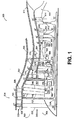
- FIG. 1 is a schematic diagram depicting an embodiment of a gas turbine in accordance with the invention.
- FIG. 1 schematically depicts an embodiment of gas turbine in accordance with the invention.
- gas turbine 500 incorporates various components that will be described generally in sequential order starting from the upstream or inlet side.
- gas entering inlet 502 encounters a strut assembly 504, an inboard portion of which is configured as a strut 506 that mounts an adjustable inlet guide vane 508.
- the vane 508 is positioned between an outer shroud 510 and an inner shroud 512, a portion of which divides the strut assembly into inboard (strut) and outboard (vane) portions.
- the inner shroud divides the flow of gas such that an outer annular gas flow path 520 is created that surrounds an inner annular gas flow path 540.
- gas travelling along the gas flow path 520 interacts with tip rotor blades 522 of an outboard, auxiliary fan 524.
- the tip rotor blades are mounted to distal ends of radially extending spokes 526 of a Cortland Burge Wheel (CBW) that is driven by a spool 538.
- the spokes of this embodiment are not aerodynamic bodies, in that the spokes are designed not to impact flow characteristics of the gas travelling through the spokes substantially.
- gas travelling along the gas flow path 520 encounters an adjustable exit guide vane 528. Thereafter, the gas is directed through the annular path between adjacent shrouds 510, 512 before exiting as exhaust.
- the gas encounters an adjustable inlet guide vane 542 that, in this embodiment, incorporates a fixed leading edge portion 544 and a variable trailing edge portion 546.
- a multi-stage fan 550 Downstream of the vane 542, a multi-stage fan 550 is positioned.
- the multi-stage fan incorporates a first set of blades 552 and a second set of blades 554 between which is interposed a set of adjustable stator vanes 556.
- the second set of fan blades 554 is driven by a spool 558 at a higher rotational speed than the rotational speed of the first set of blades 552.
- a gear assembly 560 is mechanically coupled between the first set of fan blades and the spool 558 so that the blades of the first set exhibit a slower rotational speed.
- the gear assembly 560 incorporates an epicyclic gear, the ring 562 of which is coupled to the first set of fan blades and the sun gear 564 of which is coupled to the spool 558 for driving the second set of fan blades.
- the planet gears 566 are held by a carrier 568 that is fixed in position by mounting to a non-moving portion of the gas turbine.
- the carrier is attached to the fixed leading edge portion 544 of the vane 542.
- the sun gear 564 includes an aperture through which spool 538 passes.
- the gas flow diverges again. This time, the inner annular gas flow path 540 is separated into a gas flow path 570 and a gas flow path 572.
- Each of these gas flow paths incorporates an adjustable inlet guide vane (574, 576) at its respective inlet.
- the vanes 574, 576 are separately controllable to provide highly adjustable flow controllability.
- a set of blades 578 of a high pressure compressor 580 is located downstream of the vanes 574, 576 along each of the gas flow paths 570, 572. Specifically, in this embodiment, the set of blades 578 forms a first stage of the high pressure compressor, with outboard portions 579 being located along the path 572 and inboard portions 581 being located along the path 570. Others of the sets of blades of the high pressure compressor (in this case, all of the subsequent sets of blades) are located only along the innermost gas flow path 570. Despite being driven by the same spool 582, the first set of blades is driven at a slower rotational speed than at least some of the other blades of the high pressure compressor. This is accomplished by mechanically coupling a gear assembly 584 between the first set of blades and the spool 582.
- the gear assembly includes an epicyclic gear, the ring gear 586 of which is coupled to the first set of blades and the sun gear 588 of which is coupled to the spool.
- carrier 590 that holds the planet gears 592 is fixed in position relative to the gas turbine by attachment to the turbine casing 594.
- the sun gear 588 includes an aperture through which spools 558 and 538 pass.
- gas encounters an adjustable guide vane 596 downstream of the outboard portions of the first set of compressor blades. Thereafter, the gas travels the remainder of the gas flow path 572 as defined by the turbine casing 594 and the inner shroud 512.
- gas travelling along the gas flow path 570 is directed through a combustion section 598 and thereafter through an adjustable inlet guide vane 602 prior to entering a high pressure turbine 604. Note that the high pressure turbine is used to drive spool 582.
- An adjustable exit guide vane 606 is positioned downstream of the high pressure turbine.
- the vane 606 also functions as an adjustable inlet guide vane for an intermediate pressure turbine 608.
- the intermediate pressure turbine drives spool 558, which powers the multi-stage fan 550.
- An adjustable exit guide vane 610 is located downstream of the intermediate pressure turbine that also functions as an adjustable inlet guide vane for a low pressure turbine 612.
- the low pressure turbine drives the spool 558, which powers the auxiliary fan 524.
- An adjustable exit guide vane 614 is located downstream of the low pressure turbine.
- a mixer 620 is used to mix gas exiting from the gas flow paths 570, 572. Additionally or alternatively, fan air from the gas flow path 520 can exit through a separate nozzle, which may or may not be variable in exit area (not shown).
- an embodiment of a gas turbine such as that depicted in FIG. 1 can potentially provide enhanced flow controllability and corresponding improvements in performance at various power and operating conditions.
- allowing the low pressure turbine to drive the auxiliary fan can potentially enable improved matching of the flow and power requirements of the auxiliary fan with the flow and power output of the low power turbine.
- this matching can be enhanced by the use of adjustable geometry inlet and exit guide vanes associated with the auxiliary fan, as well as adjustable geometry inlet and exit guide vanes of the low pressure turbine.
- adjustable geometry inlet and exit vanes affecting the outboard portions of the blades of the high pressure compressor can enable an improved matching of the flow and pressure of the gas flow path 570 with the exit flow and pressure of the gas flow path 572. Such improved matching can potentially reduce turbine screech, for example.
- improved matching of the speed, flow and power of each spool can be achieved by the adjustable geometry inlet and exit vanes of each of the turbines.
- use of a gear assembly can enable slower rotor tip speeds of at least some of the upstream blades of the high pressure compressor and higher rotor tip speeds of at least some of the downstream blades of the high pressure compressor.
- use of a gear assembly can enable at least one upstream stage of a multi-stage fan to exhibit a slower rotor tip speed than the rotor tip speed at least one downstream stage.
Landscapes
- Engineering & Computer Science (AREA)
- Chemical & Material Sciences (AREA)
- Combustion & Propulsion (AREA)
- Mechanical Engineering (AREA)
- General Engineering & Computer Science (AREA)
- Structures Of Non-Positive Displacement Pumps (AREA)
- Turbine Rotor Nozzle Sealing (AREA)
Claims (11)
- Turbine à gaz (500), comprenant :un premier passage annulaire d'écoulement de gaz (570) ;un deuxième passage annulaire d'écoulement de gaz (572) disposé vers l'extérieur dans un sens radial par rapport au premier passage d'écoulement de gaz (570) ;ordonnés en série, une soufflante à plusieurs étages (550), des parties intérieures dans un sens radial (581) d'un premier ensemble d'aubes de compresseur haute pression (578), un second ensemble d'aubes de compresseur haute pression (580), une section de combustion (598) et une turbine haute pression (604), positionnés le long du premier passage d'écoulement de gaz (570) ; etordonnées en série, la soufflante à plusieurs étages (550) et des parties extérieures dans un sens radial (579) du premier ensemble d'aubes de compresseur haute pression (578), positionnées le long du deuxième passage d'écoulement de gaz (572) de telle sorte que les parties intérieures (579) du premier ensemble d'aubes de compresseur haute pression (578), le second ensemble d'aubes de compresseur haute pression (580), la section de combustion (598) et la turbine haute pression (604) ne sont pas positionnés le long du deuxième passage d'écoulement de gaz (572) ;une première bobine (582) et une deuxième bobine (558) ;la turbine haute pression (604) fonctionnant de sorte à entraîner le premier ensemble d'aubes de compresseur haute pression (578) et les ensembles subséquents d'aubes de compresseur haute pression par l'intermédiaire de la première bobine (582) ;la soufflante à plusieurs étages (550) fonctionnant de sorte à être entraînée par la deuxième bobine (558) ;la turbine à gaz comprenant en outre :une turbine à pression inférieure (608) positionnée le long du premier passage d'écoulement de gaz (570), la turbine à pression inférieure fonctionnant de sorte à entraîner la soufflante à plusieurs étages (550) par l'intermédiaire de la deuxième bobine (558), la turbine à pression inférieure (608) étant une turbine à pression intermédiaire ;la turbine à gaz comprend en outre une turbine basse pression (612) positionnée le long du premier passage d'écoulement de gaz en aval de la turbine à pression intermédiaire (608), la turbine basse pression (612) fonctionnant de sorte à entraîner une troisième bobine (538) ;une soufflante auxiliaire (524) positionnée en amont de la soufflante à plusieurs étages (550), la soufflante auxiliaire (524) fonctionnant de sorte à être entraînée par la turbine basse pression (612) par l'intermédiaire de la troisième bobine (538) ; etun troisième passage d'écoulement de gaz (520) disposé vers l'extérieur dans un sens radial par rapport au deuxième passage d'écoulement de gaz (572) ; caractérisée en ce que :la soufflante auxiliaire (524) fonctionne de sorte à diriger un écoulement de gaz le long du troisième passage d'écoulement de gaz (520) sans diriger un écoulement de gaz le long du premier passage d'écoulement de gaz (570) ou le long du deuxième passage d'écoulement de gaz (572).
- Turbine à gaz selon la revendication 1, dans laquelle :la soufflante à plusieurs étages (550) comprend un premier étage (552) et un second étage (554) ;le premier étage (552) ainsi que le second étage (554) fonctionnent de sorte à être entraînés par la deuxième bobine (558) ; etle premier étage (552) fonctionne de sorte à être entraîné à une vitesse de rotation qui est inférieure à une vitesse de rotation du second étage (554).
- Turbine à gaz selon la revendication 2, comprenant en outre une pignonnerie (560) s'engrenant avec la deuxième bobine (558) et le premier étage (552).
- Turbine à gaz selon la revendication 3, dans laquelle la pignonnerie (560) comprend un engrenage épicyclique comprenant un engrenage planétaire (564) et une couronne (562), la couronne (562) s'engrenant avec le premier étage (552), l'engrenage planétaire (564) s'engrenant avec la bobine (558).
- Turbine à gaz selon une quelconque revendication précédente, dans laquelle :le premier ensemble d'aubes de compresseur haute pression (578) fonctionne de sorte à être entraîné par la première bobine (582) à une vitesse de rotation qui est inférieure aux vitesses de rotation du second ensemble d'aubes de compresseur haute pression (580).
- Turbine à gaz selon la revendication 5, comprenant en outre une pignonnerie (584 ; 712) s'engrenant avec la première bobine (582) et avec le premier ensemble d'aubes de compresseur haute pression (578).
- Turbine à gaz selon la revendication 6, dans laquelle la pignonnerie (584) comprend un engrenage épicyclique comprenant un engrenage planétaire (588) et une couronne (586), la couronne (586) étant accouplée au premier ensemble d'aubes de compresseur haute pression (578), l'engrenage planétaire étant accouplé à la première bobine (582).
- Turbine à gaz selon une quelconque revendication précédente, dans laquelle le premier passage d'écoulement de gaz (570) et le deuxième passage d'écoulement de gaz (572) s'écartent l'un de l'autre en aval de la soufflante à plusieurs étages (550).
- Turbine à gaz selon une quelconque revendication précédente, dans laquelle le troisième passage d'écoulement de gaz (520) s'écarte du premier passage d'écoulement de gaz (570) et du deuxième passage d'écoulement de gaz (572) en amont de la soufflante auxiliaire (524).
- Turbine à gaz selon une quelconque revendication précédente, dans laquelle ;
la soufflante auxiliaire (524) comprend des rotors d'extrémité ; et
des rayons (526) s'étendent vers l'intérieur dans un sens radial à partir desdits rotors d'extrémité à travers une partie de la turbine à gaz en amont d'un emplacement dans lequel le premier passage d'écoulement de gaz (570) et le deuxième passage d'écoulement de gaz (572) deviennent divergents. - Turbine à gaz selon la revendication 10, dans laquelle :les rayons (526) ne sont pas des corps aérodynamiques.
Applications Claiming Priority (1)
| Application Number | Priority Date | Filing Date | Title |
|---|---|---|---|
| US11/770,008 US8104265B2 (en) | 2007-06-28 | 2007-06-28 | Gas turbines with multiple gas flow paths |
Publications (3)
| Publication Number | Publication Date |
|---|---|
| EP2009270A2 EP2009270A2 (fr) | 2008-12-31 |
| EP2009270A3 EP2009270A3 (fr) | 2012-04-04 |
| EP2009270B1 true EP2009270B1 (fr) | 2016-05-04 |
Family
ID=39591776
Family Applications (1)
| Application Number | Title | Priority Date | Filing Date |
|---|---|---|---|
| EP08251269.0A Active EP2009270B1 (fr) | 2007-06-28 | 2008-03-31 | Turbine à gaz dotée de multiples passages d'écoulement de gaz |
Country Status (2)
| Country | Link |
|---|---|
| US (1) | US8104265B2 (fr) |
| EP (1) | EP2009270B1 (fr) |
Families Citing this family (26)
| Publication number | Priority date | Publication date | Assignee | Title |
|---|---|---|---|---|
| US20140174056A1 (en) | 2008-06-02 | 2014-06-26 | United Technologies Corporation | Gas turbine engine with low stage count low pressure turbine |
| US8128021B2 (en) | 2008-06-02 | 2012-03-06 | United Technologies Corporation | Engine mount system for a turbofan gas turbine engine |
| US20110167831A1 (en) * | 2009-09-25 | 2011-07-14 | James Edward Johnson | Adaptive core engine |
| US9353684B2 (en) * | 2009-12-11 | 2016-05-31 | Northrop Grumman Systems Corporation | Aircraft engine airflow modulation apparatus and method for engine bay cooling and cycle flow matching |
| US9239012B2 (en) | 2011-06-08 | 2016-01-19 | United Technologies Corporation | Flexible support structure for a geared architecture gas turbine engine |
| US9410608B2 (en) | 2011-06-08 | 2016-08-09 | United Technologies Corporation | Flexible support structure for a geared architecture gas turbine engine |
| US9631558B2 (en) | 2012-01-03 | 2017-04-25 | United Technologies Corporation | Geared architecture for high speed and small volume fan drive turbine |
| US9003808B2 (en) * | 2011-11-02 | 2015-04-14 | United Technologies Corporation | Turbofan with gear-driven compressor and fan-driven core |
| US10287914B2 (en) | 2012-01-31 | 2019-05-14 | United Technologies Corporation | Gas turbine engine with high speed low pressure turbine section and bearing support features |
| US10060390B2 (en) * | 2012-02-29 | 2018-08-28 | United Technologies Corporation | Bypass duct with angled drag links |
| US20130219907A1 (en) * | 2012-02-29 | 2013-08-29 | Frederick M. Schwarz | Geared turbofan architecture for improved thrust density |
| US10125693B2 (en) | 2012-04-02 | 2018-11-13 | United Technologies Corporation | Geared turbofan engine with power density range |
| US10018119B2 (en) * | 2012-04-02 | 2018-07-10 | United Technologies Corporation | Geared architecture with inducer for gas turbine engine |
| EP2662535A1 (fr) * | 2012-05-07 | 2013-11-13 | Siemens Aktiengesellschaft | Rotor pour une turbine à vapeur et turbine à vapeur correspondante |
| US9157366B2 (en) | 2012-05-30 | 2015-10-13 | United Technologies Corporation | Adaptive fan with cold turbine |
| US20150308351A1 (en) | 2012-05-31 | 2015-10-29 | United Technologies Corporation | Fundamental gear system architecture |
| US8756908B2 (en) | 2012-05-31 | 2014-06-24 | United Technologies Corporation | Fundamental gear system architecture |
| US8572943B1 (en) | 2012-05-31 | 2013-11-05 | United Technologies Corporation | Fundamental gear system architecture |
| US9506423B2 (en) | 2013-03-14 | 2016-11-29 | United Technologies Corporation | Flow control device for a three stream turbofan engine |
| US9488101B2 (en) | 2013-03-14 | 2016-11-08 | United Technologies Corporation | Adaptive fan reverse core geared turbofan engine with separate cold turbine |
| US9850822B2 (en) | 2013-03-15 | 2017-12-26 | United Technologies Corporation | Shroudless adaptive fan with free turbine |
| IL228274A (en) | 2013-09-03 | 2016-10-31 | Israel Aerospace Ind Ltd | Fan Turbo Engine and Method of Removing Fan Fan Turbo |
| US10669946B2 (en) | 2015-06-05 | 2020-06-02 | Raytheon Technologies Corporation | Geared architecture for a gas turbine engine |
| US10711702B2 (en) * | 2015-08-18 | 2020-07-14 | General Electric Company | Mixed flow turbocore |
| US10578028B2 (en) | 2015-08-18 | 2020-03-03 | General Electric Company | Compressor bleed auxiliary turbine |
| FR3047519B1 (fr) * | 2016-02-08 | 2018-01-19 | Safran Aircraft Engines | Systeme de mise en rotation d'une soufflante d'un turboreacteur |
Citations (1)
| Publication number | Priority date | Publication date | Assignee | Title |
|---|---|---|---|---|
| EP1653064A2 (fr) * | 2004-10-29 | 2006-05-03 | General Electric Company | Turbine à gaz avec aubes contre-rotatives |
Family Cites Families (25)
| Publication number | Priority date | Publication date | Assignee | Title |
|---|---|---|---|---|
| US3282053A (en) * | 1966-11-01 | Ducted fan arrangement for aircraft | ||
| GB1309721A (en) * | 1971-01-08 | 1973-03-14 | Secr Defence | Fan |
| US3861139A (en) * | 1973-02-12 | 1975-01-21 | Gen Electric | Turbofan engine having counterrotating compressor and turbine elements and unique fan disposition |
| GB1484898A (en) * | 1974-09-11 | 1977-09-08 | Rolls Royce | Ducted fan gas turbine engine |
| US4070825A (en) * | 1974-11-26 | 1978-01-31 | United Turbine Ab & Co. | Gas turbine power plant |
| US4010608A (en) * | 1975-06-16 | 1977-03-08 | General Electric Company | Split fan work gas turbine engine |
| FR2461820A1 (fr) * | 1979-07-16 | 1981-02-06 | Snecma | Turboreacteur multiflux a taux de dilution pilotable |
| US4704862A (en) * | 1985-05-29 | 1987-11-10 | United Technologies Corporation | Ducted prop engine |
| GB8630754D0 (en) * | 1986-12-23 | 1987-02-04 | Rolls Royce Plc | Turbofan gas turbine engine |
| GB2209575A (en) * | 1987-09-05 | 1989-05-17 | Rolls Royce Plc | A gearbox arrangement for driving contra-rotating multi-bladed rotors |
| JPH03504408A (ja) * | 1989-02-27 | 1991-09-26 | ユナイテッド・テクノロジーズ・コーポレイション | ガスタービンエンジンの制御装置 |
| GB9313905D0 (en) * | 1993-07-06 | 1993-08-25 | Rolls Royce Plc | Shaft power transfer in gas turbine engines |
| US5402638A (en) * | 1993-10-04 | 1995-04-04 | General Electric Company | Spillage drag reducing flade engine |
| US5485717A (en) * | 1994-06-29 | 1996-01-23 | Williams International Corporation | Multi-spool by-pass turbofan engine |
| US5687563A (en) * | 1996-01-22 | 1997-11-18 | Williams International Corporation | Multi-spool turbofan engine with turbine bleed |
| US5816042A (en) * | 1996-12-27 | 1998-10-06 | United Technologies Corporation | Flow diverter system for multiple streams for gas turbine engines |
| FR2759734B1 (fr) * | 1997-02-20 | 1999-04-09 | Snecma | Turbomachine a systeme de compression optimise |
| US6209311B1 (en) * | 1998-04-13 | 2001-04-03 | Nikkiso Company, Ltd. | Turbofan engine including fans with reduced speed |
| US7058556B2 (en) * | 2001-09-26 | 2006-06-06 | Goodrich Pump & Engine Control Systems, Inc. | Adaptive aero-thermodynamic engine model |
| US6647708B2 (en) * | 2002-03-05 | 2003-11-18 | Williams International Co., L.L.C. | Multi-spool by-pass turbofan engine |
| US7246484B2 (en) * | 2003-08-25 | 2007-07-24 | General Electric Company | FLADE gas turbine engine with counter-rotatable fans |
| FR2866387B1 (fr) * | 2004-02-12 | 2008-03-14 | Snecma Moteurs | Adaptation aerodynamique de la soufflante arriere d'un turboreacteur double soufflante |
| US7144221B2 (en) * | 2004-07-30 | 2006-12-05 | General Electric Company | Method and apparatus for assembling gas turbine engines |
| GB0502324D0 (en) * | 2005-03-14 | 2005-03-16 | Rolls Royce Plc | A multi-shaft arrangement for a turbine engine |
| US7614210B2 (en) * | 2006-02-13 | 2009-11-10 | General Electric Company | Double bypass turbofan |
-
2007
- 2007-06-28 US US11/770,008 patent/US8104265B2/en active Active
-
2008
- 2008-03-31 EP EP08251269.0A patent/EP2009270B1/fr active Active
Patent Citations (1)
| Publication number | Priority date | Publication date | Assignee | Title |
|---|---|---|---|---|
| EP1653064A2 (fr) * | 2004-10-29 | 2006-05-03 | General Electric Company | Turbine à gaz avec aubes contre-rotatives |
Also Published As
| Publication number | Publication date |
|---|---|
| EP2009270A2 (fr) | 2008-12-31 |
| EP2009270A3 (fr) | 2012-04-04 |
| US8104265B2 (en) | 2012-01-31 |
| US20090000265A1 (en) | 2009-01-01 |
Similar Documents
| Publication | Publication Date | Title |
|---|---|---|
| EP2009270B1 (fr) | Turbine à gaz dotée de multiples passages d'écoulement de gaz | |
| EP2009262B1 (fr) | Turbine à gaz comprenant des multiples voies d'écoulement de gaz | |
| EP2009269B1 (fr) | Turbine à gaz dotée de multiples voies d'écoulement de gaz | |
| US9726113B2 (en) | Turbine engine assembly and methods of assembling same | |
| US20130192256A1 (en) | Geared turbofan engine with counter-rotating shafts | |
| US8096753B2 (en) | Tip turbine engine and operating method with reverse core airflow | |
| CN109196187B (zh) | 用于两框架式燃气涡轮发动机的方法和系统 | |
| CN109723559B (zh) | 包括双速分离式压缩机的燃气涡轮发动机 | |
| US20180080411A1 (en) | Gas turbine engine | |
| CA2720157A1 (fr) | Turbine a gaz avec soufflantes exterieures | |
| US20130276424A1 (en) | Low Noise Compressor Rotor for Geared Turbofan Engine | |
| US20110150633A1 (en) | Intermediate fan stage | |
| EP2994628A2 (fr) | Section avant de moteur à turboréacteur | |
| US20130195624A1 (en) | Geared turbofan engine with counter-rotating shafts | |
| CA2720158A1 (fr) | Soufflante etagee de peripherie | |
| JP2017198208A (ja) | ターボファン組立体および組立方法 | |
| US20110150627A1 (en) | Method of operating a fan system | |
| EP3008323A2 (fr) | Section avant de moteur a turboreacteur | |
| EP2336522B1 (fr) | Fan à étage intermédiaire | |
| US20190153959A1 (en) | Gas turbine engine geared architecture | |
| EP3464823A1 (fr) | Système pour turbine basse-pression à faible tourbillon | |
| US20160348591A1 (en) | Geared turbofan engine with counter-rotating shafts | |
| US12410722B2 (en) | Circumferential row of vanes for a gas turbine engine and having non-uniform vane spacing | |
| EP2935791A1 (fr) | Soufflante carénée légère |
Legal Events
| Date | Code | Title | Description |
|---|---|---|---|
| PUAI | Public reference made under article 153(3) epc to a published international application that has entered the european phase |
Free format text: ORIGINAL CODE: 0009012 |
|
| AK | Designated contracting states |
Kind code of ref document: A2 Designated state(s): AT BE BG CH CY CZ DE DK EE ES FI FR GB GR HR HU IE IS IT LI LT LU LV MC MT NL NO PL PT RO SE SI SK TR |
|
| AX | Request for extension of the european patent |
Extension state: AL BA MK RS |
|
| PUAL | Search report despatched |
Free format text: ORIGINAL CODE: 0009013 |
|
| AK | Designated contracting states |
Kind code of ref document: A3 Designated state(s): AT BE BG CH CY CZ DE DK EE ES FI FR GB GR HR HU IE IS IT LI LT LU LV MC MT NL NO PL PT RO SE SI SK TR |
|
| AX | Request for extension of the european patent |
Extension state: AL BA MK RS |
|
| RIC1 | Information provided on ipc code assigned before grant |
Ipc: F02K 3/077 20060101AFI20120229BHEP Ipc: F02C 3/06 20060101ALI20120229BHEP |
|
| 17P | Request for examination filed |
Effective date: 20121002 |
|
| AKX | Designation fees paid |
Designated state(s): DE GB |
|
| 17Q | First examination report despatched |
Effective date: 20130724 |
|
| GRAP | Despatch of communication of intention to grant a patent |
Free format text: ORIGINAL CODE: EPIDOSNIGR1 |
|
| INTG | Intention to grant announced |
Effective date: 20160204 |
|
| GRAS | Grant fee paid |
Free format text: ORIGINAL CODE: EPIDOSNIGR3 |
|
| GRAA | (expected) grant |
Free format text: ORIGINAL CODE: 0009210 |
|
| AK | Designated contracting states |
Kind code of ref document: B1 Designated state(s): DE GB |
|
| REG | Reference to a national code |
Ref country code: GB Ref legal event code: FG4D |
|
| REG | Reference to a national code |
Ref country code: DE Ref legal event code: R096 Ref document number: 602008043966 Country of ref document: DE |
|
| RAP2 | Party data changed (patent owner data changed or rights of a patent transferred) |
Owner name: UNITED TECHNOLOGIES CORPORATION |
|
| REG | Reference to a national code |
Ref country code: DE Ref legal event code: R097 Ref document number: 602008043966 Country of ref document: DE |
|
| PLBE | No opposition filed within time limit |
Free format text: ORIGINAL CODE: 0009261 |
|
| STAA | Information on the status of an ep patent application or granted ep patent |
Free format text: STATUS: NO OPPOSITION FILED WITHIN TIME LIMIT |
|
| 26N | No opposition filed |
Effective date: 20170207 |
|
| REG | Reference to a national code |
Ref country code: DE Ref legal event code: R082 Ref document number: 602008043966 Country of ref document: DE Representative=s name: SCHMITT-NILSON SCHRAUD WAIBEL WOHLFROM PATENTA, DE |
|
| REG | Reference to a national code |
Ref country code: DE Ref legal event code: R082 Ref document number: 602008043966 Country of ref document: DE Representative=s name: SCHMITT-NILSON SCHRAUD WAIBEL WOHLFROM PATENTA, DE Ref country code: DE Ref legal event code: R081 Ref document number: 602008043966 Country of ref document: DE Owner name: UNITED TECHNOLOGIES CORP. (N.D.GES.D. STAATES , US Free format text: FORMER OWNER: UNITED TECHNOLOGIES CORPORATION, HARTFORD, CONN., US |
|
| REG | Reference to a national code |
Ref country code: DE Ref legal event code: R081 Ref document number: 602008043966 Country of ref document: DE Owner name: RAYTHEON TECHNOLOGIES CORPORATION (N.D.GES.D.S, US Free format text: FORMER OWNER: UNITED TECHNOLOGIES CORP. (N.D.GES.D. STAATES DELAWARE), FARMINGTON, CONN., US Ref country code: DE Ref legal event code: R081 Ref document number: 602008043966 Country of ref document: DE Owner name: RTX CORPORATION (N.D.GES.D. STAATES DELAWARE),, US Free format text: FORMER OWNER: UNITED TECHNOLOGIES CORP. (N.D.GES.D. STAATES DELAWARE), FARMINGTON, CONN., US |
|
| P01 | Opt-out of the competence of the unified patent court (upc) registered |
Effective date: 20230519 |
|
| REG | Reference to a national code |
Ref country code: DE Ref legal event code: R081 Ref document number: 602008043966 Country of ref document: DE Owner name: RTX CORPORATION (N.D.GES.D. STAATES DELAWARE),, US Free format text: FORMER OWNER: RAYTHEON TECHNOLOGIES CORPORATION (N.D.GES.D.STAATES DELAWARE), ARLINGTON, VA, US |
|
| PGFP | Annual fee paid to national office [announced via postgrant information from national office to epo] |
Ref country code: GB Payment date: 20260219 Year of fee payment: 19 |
|
| PGFP | Annual fee paid to national office [announced via postgrant information from national office to epo] |
Ref country code: DE Payment date: 20260219 Year of fee payment: 19 |