EP2009305A1 - Element externe d'embrayage pour embrayage multidisque - Google Patents
Element externe d'embrayage pour embrayage multidisque Download PDFInfo
- Publication number
- EP2009305A1 EP2009305A1 EP06798184A EP06798184A EP2009305A1 EP 2009305 A1 EP2009305 A1 EP 2009305A1 EP 06798184 A EP06798184 A EP 06798184A EP 06798184 A EP06798184 A EP 06798184A EP 2009305 A1 EP2009305 A1 EP 2009305A1
- Authority
- EP
- European Patent Office
- Prior art keywords
- spline
- clutch
- outer member
- fins
- grooves
- Prior art date
- Legal status (The legal status is an assumption and is not a legal conclusion. Google has not performed a legal analysis and makes no representation as to the accuracy of the status listed.)
- Granted
Links
- 230000002093 peripheral effect Effects 0.000 claims abstract description 16
- 230000004069 differentiation Effects 0.000 abstract description 2
- 238000000034 method Methods 0.000 description 4
- 239000000463 material Substances 0.000 description 2
- 229910000838 Al alloy Inorganic materials 0.000 description 1
- 230000005540 biological transmission Effects 0.000 description 1
- 238000001816 cooling Methods 0.000 description 1
- 238000004512 die casting Methods 0.000 description 1
- 238000007599 discharging Methods 0.000 description 1
- 230000000694 effects Effects 0.000 description 1
- 238000012986 modification Methods 0.000 description 1
- 230000004048 modification Effects 0.000 description 1
Images


Classifications
-
- F—MECHANICAL ENGINEERING; LIGHTING; HEATING; WEAPONS; BLASTING
- F16—ENGINEERING ELEMENTS AND UNITS; GENERAL MEASURES FOR PRODUCING AND MAINTAINING EFFECTIVE FUNCTIONING OF MACHINES OR INSTALLATIONS; THERMAL INSULATION IN GENERAL
- F16D—COUPLINGS FOR TRANSMITTING ROTATION; CLUTCHES; BRAKES
- F16D13/00—Friction clutches
- F16D13/58—Details
- F16D13/60—Clutching elements
- F16D13/64—Clutch-plates; Clutch-lamellae
- F16D13/648—Clutch-plates; Clutch-lamellae for clutches with multiple lamellae
-
- F—MECHANICAL ENGINEERING; LIGHTING; HEATING; WEAPONS; BLASTING
- F16—ENGINEERING ELEMENTS AND UNITS; GENERAL MEASURES FOR PRODUCING AND MAINTAINING EFFECTIVE FUNCTIONING OF MACHINES OR INSTALLATIONS; THERMAL INSULATION IN GENERAL
- F16D—COUPLINGS FOR TRANSMITTING ROTATION; CLUTCHES; BRAKES
- F16D13/00—Friction clutches
- F16D13/22—Friction clutches with axially-movable clutching members
- F16D13/38—Friction clutches with axially-movable clutching members with flat clutching surfaces, e.g. discs
- F16D13/52—Clutches with multiple lamellae ; Clutches in which three or more axially moveable members are fixed alternately to the shafts to be coupled and are pressed from one side towards an axially-located member
- F16D13/54—Clutches with multiple lamellae ; Clutches in which three or more axially moveable members are fixed alternately to the shafts to be coupled and are pressed from one side towards an axially-located member with means for increasing the effective force between the actuating sleeve or equivalent member and the pressure member
- F16D13/56—Clutches with multiple lamellae ; Clutches in which three or more axially moveable members are fixed alternately to the shafts to be coupled and are pressed from one side towards an axially-located member with means for increasing the effective force between the actuating sleeve or equivalent member and the pressure member in which the clutching pressure is produced by springs only
-
- F—MECHANICAL ENGINEERING; LIGHTING; HEATING; WEAPONS; BLASTING
- F16—ENGINEERING ELEMENTS AND UNITS; GENERAL MEASURES FOR PRODUCING AND MAINTAINING EFFECTIVE FUNCTIONING OF MACHINES OR INSTALLATIONS; THERMAL INSULATION IN GENERAL
- F16D—COUPLINGS FOR TRANSMITTING ROTATION; CLUTCHES; BRAKES
- F16D2300/00—Special features for couplings or clutches
- F16D2300/12—Mounting or assembling
Definitions
- the present invention relates to an improvement of a clutch outer member for a multi-plate clutch, the clutch outer member including an end wall, a large number of fins extending axially from an outer peripheral part of the end wall and arranged at equal intervals in the peripheral direction so as to define spline grooves therebetween, and an annular connecting part formed on the outer periphery at the extremity of this group of fins and connecting the fins integrally to each other, the fin having an axially-extending weight-reducing bottomed groove formed so as to open on an inner peripheral face thereof.
- Patent Publication 1 Japanese Patent Application Laid-open No. 2005-257032
- the weight-cutting bottomed grooves have a smaller groove width than that of the spline grooves and the clutch will not be mis-assembled, but mistakes in differentiating the spline grooves from the weight-cutting bottomed grooves affect the assembly efficiency to some extent.
- the present invention has been accomplished under the above-mentioned circumstances, and it is an object thereof to provide a clutch outer member for a multi-plate clutch, the clutch outer member enabling differentiation between a weight-cutting bottomed groove and a spline groove to be carried out quickly and appropriately and an operation of fitting spline teeth of a friction plate into the spline grooves to be carried out quickly, thus contributing to an improvement in the efficiency of assembling the clutch.
- a clutch outer member for a multi-plate clutch comprising an end wall, a large number of fins extending axially from the outer peripheral part of the end wall and arranged at equal intervals in the peripheral direction so as to define spline grooves therebetween, and an annular connecting part formed on the outer periphery at the extremity of this group of fins and connecting the fins integrally to each other, the fin having an axially-extending weight-cutting bottomed groove formed so as to open on an inner peripheral face thereof, characterized in that the annular connecting part is provided, on a part of an outer end face thereof corresponding to each of the spline grooves, with a reference notch indicating the position of the spline groove.
- an inner side face of the reference notch is flush with an inner side face of the corresponding spline groove
- the reference notches indicating the positions of the spline grooves are provided on the outer end face of the annular connecting part, in a process of assembling the clutch, when fitting spline teeth of a drive friction plate into the spline grooves of the clutch outer member, by adjusting the positions of the spline teeth of the drive friction plate so that they match the reference notch positions, these spline teeth can be fitted into the spline grooves appropriately. It is therefore possible to avoid an erroneous assembly operation due to being misled by the weight-cutting bottomed groove of each fin, thus improving the efficiency of the assembly operation.
- the reference notch is formed so as to communicate with the corresponding spline groove, some of the spline teeth can be guided to the spline grooves through the reference notches, thus further improving the efficiency of the assembly operation.
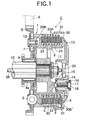
- reference symbol C denotes a multi-plate wet clutch for a two-wheeled motor vehicle.
- This clutch C includes a clutch outer member 1 having an overall bottomed cylindrical shape, a clutch inner 2 disposed concentrically within the clutch outer member 1, a plurality of drive friction plates 3 axially slidably spline-fitted into the inner periphery of the clutch outer member 1, and a plurality of driven friction plates 4 superimposed alternately on the drive friction plates 3 and axially slidably spline-fitted onto the outer periphery of the clutch inner 2.
- An input gear 8, which meshes with an engine drive gear 6, is connected to an end wall 7 of the clutch outer member 1 via a torque damper 5, and the clutch inner 2 is spline-coupled to and secured by a nut 11 to an output shaft 10 supporting a hub 8a of the input gear 8 via a needle bearing 9.
- a plurality of posts 14 are projectingly provided integrally with the clutch inner 2, the posts 14 projecting axially outward, a bottomed cylindrical support tube 15 surrounding the post 14 is formed integrally with the pressure plate 13, and a clutch spring 17 is provided in a compressed state between the base of the support tube 15 and a retainer 16 secured to the extremity of the post 14 by a bolt 18, the clutch spring 17 urging the pressure plate 13 toward the pressure-receiving plate 12 side with a predetermined set load.
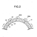
- a large number of strip-shaped friction linings 21 are bonded to opposite faces of the drive friction plate 3, which has spline teeth 20A on the outer periphery, so as to define radial oil grooves 22 therebetween.
- a large number of oil holes 23 are provided in the peripheral wall of the clutch inner 2, the oil holes 23 providing communication between the interior and the exterior of the clutch inner 2.
- the output shaft 10 is formed so as to be hollow, and a push rod 26 is disposed in the hollow part, the push rod 26 having its extremity abutting against a central area of the pressure plate 13 via a release bearing 25.
- This push rod 26 is operable in association with a clutch operation lever (not illustrated).
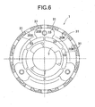
- the clutch outer member 1 of the present invention is explained in detail by reference to FIG. 3 to FIG. 6 .
- the clutch outer member 1 is produced by die-casting using an Al alloy as a material. It is formed from the end wall 7, a large number of fins 30 extending axially from an outer peripheral part of the end wall 7, and an annular connecting part 31 formed on the outer periphery of extremities of these fins 30 and connecting the fins 30 integrally to each other, and it has an overall bottomed cylindrical shape.
- the large number of fins 30 are arranged at equal intervals in the peripheral direction so as to define spline grooves 20B therebetween, and slidably fitting the spline teeth 20A (see FIG. 2 ) on the outer periphery of the drive friction plate 3 into the spline grooves 20B achieves a sliding spline fit between the clutch outer member 1 and the drive friction plates 3.
- Reference notches 32 are provided on the outer end face of the annular connecting part 31 in parts corresponding to each of the spline grooves 20B, the reference notches 32 indicating the positions of the spline grooves 20B.
- the inner face of the reference notch 32 is formed so as to be flush with the inner face of the spline groove 20B.
- a weight-cutting bottomed groove 33 is formed in each of the fins 30, the bottomed groove 33 opening on the inner peripheral face side and extending axially, and having a groove width smaller than that of the spline groove 20B.
- a bottomed auxiliary spline groove 20B' having a length smaller than the axial width of the annular connecting part 31 is provided so as to open on the extremity face of each of the fins 30 and, among the group of drive and driven friction plates 3 and 4, the spline tooth 20A of the drive friction plate 3 that is on the outermost side and in contact with the pressure plate 13 is slidably fitted into the auxiliary spline groove 20B'.
- the large number of spline grooves 20B defined by the large number of fins 30 open toward the inside and toward the outside in portions other than the annular connecting part 31, not only do they contribute to lightening the weight while enabling the spline teeth 20A of the drive friction plate 3 to be fitted thereinto, but it is also possible to promote cooling of the sections under friction between the drive and driven friction plates 3 and 4 by supplying oil to the oil grooves 22 of the drive friction plates 3 through the spline grooves 20B or discharging oil from the oil grooves 22 to the spline grooves 20B. Furthermore, since each of the fins 30 has the weight-cutting bottomed groove 33 formed so as to open on the inner peripheral face side and extend axially, and surplus material is cut away, this further contributes to lightening the weight of the clutch outer member 1.
- each of the reference notches 32 is formed so as to communicate with the corresponding spline groove 20B, some of the spline teeth 20A can be guided to the spline grooves 20B through the reference notches 32, thereby further improving the efficiency of the assembly operation.
- the present invention is not limited to the above-mentioned embodiment and may be modified in a variety of ways as long as the modifications do not depart from the spirit and scope of the invention.
- the auxiliary spline groove 20B' of each of the fins 30 is not always necessary, and the spline teeth 20A of all the drive friction plates 3 may be slidably fitted into the spline grooves 20B.
Landscapes
- Engineering & Computer Science (AREA)
- General Engineering & Computer Science (AREA)
- Mechanical Engineering (AREA)
- Mechanical Operated Clutches (AREA)
Applications Claiming Priority (2)
| Application Number | Priority Date | Filing Date | Title |
|---|---|---|---|
| JP2006114671A JP4648237B2 (ja) | 2006-04-18 | 2006-04-18 | 多板クラッチ用クラッチアウタ |
| PCT/JP2006/318692 WO2007122751A1 (fr) | 2006-04-18 | 2006-09-21 | Élément externe d'embrayage pour embrayage multidisque |
Publications (3)
| Publication Number | Publication Date |
|---|---|
| EP2009305A1 true EP2009305A1 (fr) | 2008-12-31 |
| EP2009305A4 EP2009305A4 (fr) | 2010-03-03 |
| EP2009305B1 EP2009305B1 (fr) | 2011-04-20 |
Family
ID=38624675
Family Applications (1)
| Application Number | Title | Priority Date | Filing Date |
|---|---|---|---|
| EP06798184A Ceased EP2009305B1 (fr) | 2006-04-18 | 2006-09-21 | Element externe d'embrayage pour embrayage multidisque |
Country Status (6)
| Country | Link |
|---|---|
| US (1) | US8011487B2 (fr) |
| EP (1) | EP2009305B1 (fr) |
| JP (1) | JP4648237B2 (fr) |
| CN (1) | CN101400913B (fr) |
| DE (1) | DE602006021484D1 (fr) |
| WO (1) | WO2007122751A1 (fr) |
Cited By (1)
| Publication number | Priority date | Publication date | Assignee | Title |
|---|---|---|---|---|
| EP3636946A4 (fr) * | 2018-08-13 | 2020-04-15 | Zhejiang Siekon Precision Machinery Co., Ltd. | Embrayage et véhicule pourvu dudit embrayage |
Families Citing this family (7)
| Publication number | Priority date | Publication date | Assignee | Title |
|---|---|---|---|---|
| DE102013202862B4 (de) * | 2013-02-21 | 2022-07-28 | Schaeffler Technologies AG & Co. KG | Kupplungsscheibe |
| JP6436109B2 (ja) * | 2016-01-26 | 2018-12-12 | トヨタ自動車株式会社 | 車両用変速機のクラッチ装置及びその製造方法 |
| DE102016125074A1 (de) * | 2016-10-06 | 2018-04-12 | Schaeffler Technologies AG & Co. KG | Kupplungseinrichtung |
| JP6376671B1 (ja) | 2017-04-04 | 2018-08-22 | 株式会社エフ・シー・シー | クラッチ摩擦板およびクラッチ装置 |
| WO2020229528A1 (fr) | 2019-05-14 | 2020-11-19 | Transmisiones Y Equipos Mecanicos, S.A. De Cv | Boîte à 8 vitesses |
| WO2020234082A1 (fr) * | 2019-05-17 | 2020-11-26 | Transmisiones Y Equipos Mecanicos, S.A. De Cv | Unité à double embrayage dans une boîte de vitesses |
| CN116057294B (zh) * | 2020-08-06 | 2026-06-02 | 株式会社F.C.C. | 动力传递装置 |
Family Cites Families (13)
| Publication number | Priority date | Publication date | Assignee | Title |
|---|---|---|---|---|
| US1742805A (en) * | 1926-01-19 | 1930-01-07 | Brown Lipe Gear Co | Clutch construction |
| JPS597626Y2 (ja) * | 1979-07-20 | 1984-03-08 | 本田技研工業株式会社 | 多板摩擦クラツチにおけるクラツチアウタ−の補強リング抜け止め構造 |
| JPS5618426A (en) | 1979-07-24 | 1981-02-21 | Fujitsu Ltd | Manufacture of semiconductor device |
| JP2598454B2 (ja) * | 1988-03-31 | 1997-04-09 | ジャトコ株式会社 | 自動変速機のクラッチドラム |
| JPH04272516A (ja) * | 1991-02-28 | 1992-09-29 | Suzuki Motor Corp | 多板式クラッチのクラッチハウジング |
| US5180043A (en) * | 1992-02-20 | 1993-01-19 | Koppy Corporation | Splined assembly |
| FR2712359B1 (fr) * | 1993-11-09 | 1996-01-19 | Valeo | Module d'embrayage à couvercle assujetti au volant par un montage du type montage à baïonnette. |
| JP3488517B2 (ja) * | 1994-09-29 | 2004-01-19 | ジヤトコ株式会社 | コネクティングシェルの噛み合わせ構造 |
| JP3805866B2 (ja) * | 1997-08-28 | 2006-08-09 | 富士重工業株式会社 | プラネタリギヤ式動力伝達装置、及びその製造方法 |
| JP4054512B2 (ja) * | 2000-05-26 | 2008-02-27 | 株式会社エクセディ | クラッチドラム |
| DE10239419A1 (de) * | 2002-08-28 | 2004-03-11 | Sachs Race Engineering Gmbh | Gehäuseanordnung für eine Reibungskupplung |
| JP4420701B2 (ja) * | 2004-03-15 | 2010-02-24 | 本田技研工業株式会社 | 多板式クラッチのクラッチアウタ |
| ATE482345T1 (de) * | 2006-07-28 | 2010-10-15 | Hoerbiger & Co | Lamellenträger einer reibkupplung |
-
2006
- 2006-04-18 JP JP2006114671A patent/JP4648237B2/ja not_active Expired - Fee Related
- 2006-09-21 EP EP06798184A patent/EP2009305B1/fr not_active Ceased
- 2006-09-21 WO PCT/JP2006/318692 patent/WO2007122751A1/fr not_active Ceased
- 2006-09-21 CN CN2006800537867A patent/CN101400913B/zh not_active Expired - Fee Related
- 2006-09-21 DE DE602006021484T patent/DE602006021484D1/de active Active
-
2008
- 2008-07-31 US US12/184,158 patent/US8011487B2/en active Active
Non-Patent Citations (2)
| Title |
|---|
| No further relevant documents disclosed * |
| See also references of WO2007122751A1 * |
Cited By (1)
| Publication number | Priority date | Publication date | Assignee | Title |
|---|---|---|---|---|
| EP3636946A4 (fr) * | 2018-08-13 | 2020-04-15 | Zhejiang Siekon Precision Machinery Co., Ltd. | Embrayage et véhicule pourvu dudit embrayage |
Also Published As
| Publication number | Publication date |
|---|---|
| WO2007122751A1 (fr) | 2007-11-01 |
| CN101400913A (zh) | 2009-04-01 |
| US20080296119A1 (en) | 2008-12-04 |
| JP2007285446A (ja) | 2007-11-01 |
| CN101400913B (zh) | 2011-04-20 |
| US8011487B2 (en) | 2011-09-06 |
| EP2009305B1 (fr) | 2011-04-20 |
| DE602006021484D1 (de) | 2011-06-01 |
| EP2009305A4 (fr) | 2010-03-03 |
| JP4648237B2 (ja) | 2011-03-09 |
Similar Documents
| Publication | Publication Date | Title |
|---|---|---|
| US8011487B2 (en) | Clutch outer member for multi-plate clutch | |
| US9267555B2 (en) | Lock-up device for torque converter | |
| US8424662B2 (en) | Multi-plate clutch system | |
| US20140326563A1 (en) | Lock-up device for torque converter | |
| EP2306038B1 (fr) | Système à embrayage multi-disque | |
| US8875859B2 (en) | Hydraulic clutch and transmission device provided with the same | |
| US11946513B1 (en) | Clutch device and motorcycle | |
| US20200116208A1 (en) | Inner Disc-Carrier for Wet-Type Friction-Clutch | |
| EP4310351B1 (fr) | Dispositif d'embrayage | |
| JP2008309317A (ja) | 発進装置 | |
| CN110382899B (zh) | 可拆卸的双离合器机构 | |
| US11933369B1 (en) | Clutch device, motorcycle, and method for producing pressure plate | |
| JP3585868B2 (ja) | クラッチアウタ | |
| EP4055295B1 (fr) | Ensemble cloche d'embrayage amélioré | |
| JP2019090429A (ja) | クラッチ装置 | |
| US20120132017A1 (en) | Motor vehicle transmission | |
| US9714668B2 (en) | Stamped turbine hub with centring tabs for torque converter | |
| JP3710629B2 (ja) | クラッチドラムとパーキングギアの結合構造 | |
| JP2003322239A (ja) | バッフルプレート付き流体継手 | |
| US11940013B1 (en) | Clutch device and motorcycle | |
| EP4650617A1 (fr) | Dispositif d'embrayage | |
| US20260110340A1 (en) | Clutch apparatus | |
| EP4339474B1 (fr) | Dispositif d'embrayage, motocyclette et procédé de production de plaque de pression | |
| US20260110339A1 (en) | Clutch apparatus | |
| EP3998413A1 (fr) | Dispositif d'embrayage double |
Legal Events
| Date | Code | Title | Description |
|---|---|---|---|
| PUAI | Public reference made under article 153(3) epc to a published international application that has entered the european phase |
Free format text: ORIGINAL CODE: 0009012 |
|
| 17P | Request for examination filed |
Effective date: 20080725 |
|
| AK | Designated contracting states |
Kind code of ref document: A1 Designated state(s): AT BE BG CH CY CZ DE DK EE ES FI FR GB GR HU IE IS IT LI LT LU LV MC NL PL PT RO SE SI SK TR |
|
| AX | Request for extension of the european patent |
Extension state: AL BA HR MK RS |
|
| DAX | Request for extension of the european patent (deleted) | ||
| RBV | Designated contracting states (corrected) |
Designated state(s): AT DE GB IT |
|
| A4 | Supplementary search report drawn up and despatched |
Effective date: 20100203 |
|
| GRAP | Despatch of communication of intention to grant a patent |
Free format text: ORIGINAL CODE: EPIDOSNIGR1 |
|
| GRAS | Grant fee paid |
Free format text: ORIGINAL CODE: EPIDOSNIGR3 |
|
| GRAA | (expected) grant |
Free format text: ORIGINAL CODE: 0009210 |
|
| AK | Designated contracting states |
Kind code of ref document: B1 Designated state(s): AT DE GB IT |
|
| REG | Reference to a national code |
Ref country code: GB Ref legal event code: FG4D |
|
| RIN2 | Information on inventor provided after grant (corrected) |
Inventor name: SUGITA, NORIHIRO Inventor name: SATOU, TOMOYASU Inventor name: UCHIYAMA, YOSHIMICHI |
|
| RAP2 | Party data changed (patent owner data changed or rights of a patent transferred) |
Owner name: KABUSHIKI KAISHA F.C.C. |
|
| REF | Corresponds to: |
Ref document number: 602006021484 Country of ref document: DE Date of ref document: 20110601 Kind code of ref document: P |
|
| REG | Reference to a national code |
Ref country code: DE Ref legal event code: R096 Ref document number: 602006021484 Country of ref document: DE Effective date: 20110601 |
|
| PG25 | Lapsed in a contracting state [announced via postgrant information from national office to epo] |
Ref country code: AT Free format text: LAPSE BECAUSE OF FAILURE TO SUBMIT A TRANSLATION OF THE DESCRIPTION OR TO PAY THE FEE WITHIN THE PRESCRIBED TIME-LIMIT Effective date: 20110420 |
|
| PLBE | No opposition filed within time limit |
Free format text: ORIGINAL CODE: 0009261 |
|
| STAA | Information on the status of an ep patent application or granted ep patent |
Free format text: STATUS: NO OPPOSITION FILED WITHIN TIME LIMIT |
|
| 26N | No opposition filed |
Effective date: 20120123 |
|
| REG | Reference to a national code |
Ref country code: DE Ref legal event code: R097 Ref document number: 602006021484 Country of ref document: DE Effective date: 20120123 |
|
| GBPC | Gb: european patent ceased through non-payment of renewal fee |
Effective date: 20110921 |
|
| PG25 | Lapsed in a contracting state [announced via postgrant information from national office to epo] |
Ref country code: GB Free format text: LAPSE BECAUSE OF NON-PAYMENT OF DUE FEES Effective date: 20110921 |
|
| PGFP | Annual fee paid to national office [announced via postgrant information from national office to epo] |
Ref country code: DE Payment date: 20200909 Year of fee payment: 15 |
|
| PGFP | Annual fee paid to national office [announced via postgrant information from national office to epo] |
Ref country code: IT Payment date: 20200812 Year of fee payment: 15 |
|
| REG | Reference to a national code |
Ref country code: DE Ref legal event code: R119 Ref document number: 602006021484 Country of ref document: DE |
|
| PG25 | Lapsed in a contracting state [announced via postgrant information from national office to epo] |
Ref country code: DE Free format text: LAPSE BECAUSE OF NON-PAYMENT OF DUE FEES Effective date: 20220401 |
|
| PG25 | Lapsed in a contracting state [announced via postgrant information from national office to epo] |
Ref country code: IT Free format text: LAPSE BECAUSE OF NON-PAYMENT OF DUE FEES Effective date: 20210921 |