EP2009321A2 - Stossdämpfer - Google Patents
Stossdämpfer Download PDFInfo
- Publication number
- EP2009321A2 EP2009321A2 EP08011704A EP08011704A EP2009321A2 EP 2009321 A2 EP2009321 A2 EP 2009321A2 EP 08011704 A EP08011704 A EP 08011704A EP 08011704 A EP08011704 A EP 08011704A EP 2009321 A2 EP2009321 A2 EP 2009321A2
- Authority
- EP
- European Patent Office
- Prior art keywords
- sub
- passage
- extension
- compression
- valve
- Prior art date
- Legal status (The legal status is an assumption and is not a legal conclusion. Google has not performed a legal analysis and makes no representation as to the accuracy of the status listed.)
- Withdrawn
Links
- 239000006096 absorbing agent Substances 0.000 title claims description 46
- 230000035939 shock Effects 0.000 title claims description 46
- 238000013016 damping Methods 0.000 claims abstract description 63
- 239000012530 fluid Substances 0.000 claims abstract description 40
- 238000005192 partition Methods 0.000 claims description 26
- 230000002093 peripheral effect Effects 0.000 claims description 19
- 230000008602 contraction Effects 0.000 claims description 5
- 239000000463 material Substances 0.000 claims description 2
- 229920003002 synthetic resin Polymers 0.000 claims description 2
- 239000000057 synthetic resin Substances 0.000 claims description 2
- 238000004891 communication Methods 0.000 description 32
- 230000004048 modification Effects 0.000 description 11
- 238000012986 modification Methods 0.000 description 11
- 230000006835 compression Effects 0.000 description 6
- 238000007906 compression Methods 0.000 description 6
- 230000007246 mechanism Effects 0.000 description 5
- 239000000725 suspension Substances 0.000 description 3
- 230000008859 change Effects 0.000 description 2
- 238000000034 method Methods 0.000 description 2
- 230000008569 process Effects 0.000 description 2
- 125000006850 spacer group Chemical group 0.000 description 2
- 230000003247 decreasing effect Effects 0.000 description 1
- 230000000694 effects Effects 0.000 description 1
- 239000010720 hydraulic oil Substances 0.000 description 1
- 238000004519 manufacturing process Methods 0.000 description 1
- 239000003921 oil Substances 0.000 description 1
- 230000004044 response Effects 0.000 description 1
- 238000007789 sealing Methods 0.000 description 1
- 238000005245 sintering Methods 0.000 description 1
Images




Classifications
-
- F—MECHANICAL ENGINEERING; LIGHTING; HEATING; WEAPONS; BLASTING
- F16—ENGINEERING ELEMENTS AND UNITS; GENERAL MEASURES FOR PRODUCING AND MAINTAINING EFFECTIVE FUNCTIONING OF MACHINES OR INSTALLATIONS; THERMAL INSULATION IN GENERAL
- F16F—SPRINGS; SHOCK-ABSORBERS; MEANS FOR DAMPING VIBRATION
- F16F9/00—Springs, vibration-dampers, shock-absorbers, or similarly-constructed movement-dampers using a fluid or the equivalent as damping medium
- F16F9/32—Details
- F16F9/34—Special valve constructions; Shape or construction of throttling passages
- F16F9/3405—Throttling passages in or on piston body, e.g. slots
-
- F—MECHANICAL ENGINEERING; LIGHTING; HEATING; WEAPONS; BLASTING
- F16—ENGINEERING ELEMENTS AND UNITS; GENERAL MEASURES FOR PRODUCING AND MAINTAINING EFFECTIVE FUNCTIONING OF MACHINES OR INSTALLATIONS; THERMAL INSULATION IN GENERAL
- F16F—SPRINGS; SHOCK-ABSORBERS; MEANS FOR DAMPING VIBRATION
- F16F9/00—Springs, vibration-dampers, shock-absorbers, or similarly-constructed movement-dampers using a fluid or the equivalent as damping medium
- F16F9/32—Details
- F16F9/34—Special valve constructions; Shape or construction of throttling passages
- F16F9/348—Throttling passages in the form of annular discs or other plate-like elements which may or may not have a spring action, operating in opposite directions or singly, e.g. annular discs positioned on top of the valve or piston body
- F16F9/3482—Throttling passages in the form of annular discs or other plate-like elements which may or may not have a spring action, operating in opposite directions or singly, e.g. annular discs positioned on top of the valve or piston body the annular discs being incorporated within the valve or piston body
-
- F—MECHANICAL ENGINEERING; LIGHTING; HEATING; WEAPONS; BLASTING
- F16—ENGINEERING ELEMENTS AND UNITS; GENERAL MEASURES FOR PRODUCING AND MAINTAINING EFFECTIVE FUNCTIONING OF MACHINES OR INSTALLATIONS; THERMAL INSULATION IN GENERAL
- F16F—SPRINGS; SHOCK-ABSORBERS; MEANS FOR DAMPING VIBRATION
- F16F9/00—Springs, vibration-dampers, shock-absorbers, or similarly-constructed movement-dampers using a fluid or the equivalent as damping medium
- F16F9/32—Details
- F16F9/34—Special valve constructions; Shape or construction of throttling passages
- F16F9/348—Throttling passages in the form of annular discs or other plate-like elements which may or may not have a spring action, operating in opposite directions or singly, e.g. annular discs positioned on top of the valve or piston body
- F16F9/3484—Throttling passages in the form of annular discs or other plate-like elements which may or may not have a spring action, operating in opposite directions or singly, e.g. annular discs positioned on top of the valve or piston body characterised by features of the annular discs per se, singularly or in combination
Definitions
- the present invention relates to shock absorbers such as a hydraulic shock absorber attached to a suspension system of a vehicle, for example, an automobile.
- cylinder-type hydraulic shock absorbers attached to suspension systems of automobiles or other vehicles are structured as follows.
- a piston connected with a piston rod is slidably fitted in a cylinder having a hydraulic fluid sealed therein.
- the piston is provided with a damping force generating mechanism including an orifice and a disk valve.
- the damping force generating mechanism generates a damping force by controlling, through the orifice and the disk valve, the flow of hydraulic fluid induced by sliding movement of the piston in the cylinder, which is caused by the extension and contraction of the piston rod.
- the orifice When the piston speed is low (i.e. in a low piston speed region), the orifice generates a damping force of orifice characteristics.
- the disk valve deflects to open, thereby generating a damping force of valve characteristics.
- the conventional hydraulic shock absorber enables damping force characteristics to be set for each of the low, intermediate and high piston speed regions. For example, for the low piston speed region, damping force characteristics are set on the basis of the orifice area. For the intermediate piston speed region, damping force characteristics are set based on the valve opening point of the disk valve. For the high piston speed region, damping force characteristics are set on the basis of the flexural rigidity of the disk valve after it has been opened.
- Japanese Patent Application Publication No. 2005-188602 discloses a hydraulic shock absorber using a piston having a split structure to enable complicated hydraulic fluid passages to be readily made by die forming process.
- the above-described conventional hydraulic shock absorber suffers, however, from the following problems. It is necessary in order to improve both the ride quality and steering stability of the vehicle to set optimal damping force characteristics for each of the low, intermediate and high piston speed regions.
- damping force in the high piston speed region is increased by increasing the flexural rigidity of the disk valve, for example, by increasing the plate thickness of the disk valve or increasing the number of disks stacked.
- an increase in the flexural rigidity of the disk valve causes a change in the valve opening characteristics of the disk valve.
- damping force in the intermediate piston speed region increases excessively.
- damping force in the intermediate piston speed region is adjusted by increasing the orifice area, damping force in the low piston speed region becomes insufficient.
- damping force characteristics in the low, intermediate and high piston speed regions interfere with each other. Accordingly, the degree of freedom for setting damping force characteristics is low, and it is difficult to set optimal damping force characteristics for each of the low, intermediate and high piston speed regions.
- an object of the present invention is to provide a shock absorber capable of increasing the degree of freedom for setting damping force characteristics.
- the present invention provides a shock absorber including a cylinder, a piston, a piston rod, a partition member, an extension-side valve, a compression-side valve, at least one sub-passage, and at least one sub-valve.
- the cylinder has a fluid sealed therein.
- the piston is slidably fitted in the cylinder.
- the piston rod is connected at one end thereof to the piston.
- the other end of the piston rod extends to the outside of the cylinder.
- the partition member has an extension-side passage and a compression-side passage in which a flow of fluid is induced by sliding movement of the piston caused by extension and contraction of the piston rod.
- the extension-side valve is provided at one side of the partition member to adjust the flow path of the extension-side passage.
- the compression-side valve is provided at the other side of the partition member to adjust the flow path of the compression-side passage.
- the at least one sub-passage is provided in the partition member to communicate between the extension-side passage and the compression-side passage. The at least one sub-valve adjusts the flow path of the sub-passage.
- a hydraulic shock absorber 1 is a cylinder-type hydraulic shock absorber attached to a suspension system of an automobile.
- a piston 2 partition member
- the piston 2 divides the inside of the cylinder 1a into two chambers, i.e. a cylinder upper chamber A and a cylinder lower chamber B.
- One end portion of a piston rod 3 extends through the piston 2 and is connected thereto with a nut 4.
- the other end portion of the piston rod 3 extends to the outside of the cylinder 1a through a rod guide 1b and an oil seal 1c that are fitted to the upper end of the cylinder 1a.
- a free piston 1d is slidably fitted in the bottom of the cylinder 1a to form a gas chamber 1e to compensate for a volumetric change in the cylinder 1a due to extension and contraction of the piston rod 3 by the compression and expansion of gas in the gas chamber le.
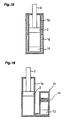
- the structure may be as follows. As shown in Fig. 18 , a reservoir 1g having a hydraulic fluid and gas sealed therein is connected to the bottom of the cylinder 1a through a base valve 1f (partition member).
- the piston 2 has a halved structure comprising an upper first piston half 5 (first member) and a lower second piston half 6 (second member) that are joined together.
- the first piston half 5 has a circular fitting opening 7 extending through the center thereof.
- the one end portion of the piston rod 3 is inserted through the fitting opening 7.
- a plurality (5 in the illustrated example) of large-diameter main passages 8 and a plurality (5 in the illustrated example) of small-diameter sub-passages 9 are circumferentially equally and alternately spaced around the opening 7 to extend through and in an axial direction of the first piston half 5.
- the first piston half 5 further has inlet passages 10 extending through and in an axial direction of an outer peripheral portion thereof outside the sub-passages 9. There are provided the same number of inlet passages 10 as the sub-passages 9, and each inlet passage 10 has a rectangular opening.
- the sub-passages 9, which are disposed at the inner peripheral side of the first piston half 5, and the inlet passages 10, which are disposed at the outer peripheral side of the first piston half 5, are communicated with each other at the side of the first piston half 5 where it is joined to the second piston half 6.
- the first piston half 5 has an annular seat portion 11 (compression-side seat portion) projecting from the upper end surface thereof between the openings of the main passages 8 and sub-passages 9 on the inner side one hand, which are disposed at the inner peripheral side, and on the other the openings of the inlet passages 10, which are disposed at the outer peripheral side. Consequently, the main passages 8 and the sub-passages 9 are disposed at the inner peripheral side of the seat portion 11, and the inlet passages 10 are disposed at the outer peripheral side of the seat portion 11.
- the first piston half 5 further has an annular sub-seat portion 12 projecting from the upper end surface thereof.
- the sub-seat portion 12 is disposed in a petal shape to surround the respective openings of the five sub-passages 9.
- the seat portion 11 projects higher than the sub-seat portion 12.
- the second piston half 6 has the same or substantially the same configuration as that of the first piston half 5.
- the second piston half 6 is provided with a fitting opening 13, main passages 14, sub-passages 15, inlet passages 16, a seat portion 17 (extension-side seat portion), and a sub-seat portion 18.
- the first piston half 5 and the second piston half 6 are joined together, being circumferentially offset relative to each other by a predetermined central angle to enable the main passages 8 of the first piston half 5 and the inlet passages 16 (and hence the sub-passages 15) of the second piston half 6 to be connected to each other and also enable the inlet passages 10 (and hence the sub-passages 9) of the first piston half 5 and the main passages 14 of the second piston half 6 to be connected to each other at the surfaces of the first and second piston halves 5 and 6 where the first and second piston halves 5 and 6 are joined together.
- a large-diameter compression-side main disk valve 19 (compression-side valve) is seated on the seat portion 11 of the first piston half 5, and a small-diameter extension-side sub disk valve 20 (extension-side sub-valve) is seated on the sub-seat portion 12 of the first piston half 5.
- a large-diameter extension-side main disk valve 21 (extension-side valve) is seated on the seat portion 17 of the second piston half 6, and a small-diameter compression-side sub disk valve 22 (compression-side sub-valve) is seated on the sub-seat portion 18 of the second piston half 6.
- the valve opening pressure of the extension-side sub disk valve 20 is set lower than that of the extension-side main disk valve 21.
- the valve opening pressure of the compression-side sub disk valve 22 is set lower than that of the compression-side main disk valve 19.
- These disk valves are each clamped at the inner peripheral side thereof by tightening of the nut 4 and allowed to deflect at the outer peripheral side thereof and thus lifted from the associated seat portion to open.
- a spacer 23 is interposed between the respective clamped portions of the compression-side main disk valve 19 and the extension-side sub disk valve 20, thereby allowing the compression-side main disk valve 19 and the extension-side sub disk valve 20 to open and close independently of each other.
- a spacer 24 is interposed between the respective clamped portions of the extension-side main disk valve 21 and the compression-side sub disk valve 22, thereby allowing the extension-side main disk valve 21 and the compression-side sub disk valve 22 to open and close independently of each other.
- the compression-side main disk valve 19 and the extension-side main disk valve 21 are provided with orifices 19A and 21A (cut portions), respectively, which bypass the associated main disk valves 19 and 21 at all times.
- the hydraulic fluid flowing through the inlet passages 10 passes through the sub-passages 9 and opens the extension-side sub disk valve 20 to pass through an annular chamber S surrounded by the sub-seat portion 12 and the compression-side main disk valve 19 and further passes through the compression-side passage D (formed from the main passages 8 and the inlet passages 16) to flow into the cylinder lower chamber B, thereby generating a damping force in accordance with the degree of opening of the extension-side sub disk valve 20.
- the orifice 21A generates a damping force in the low piston speed region.
- the extension-side main disk valve 21 generates a damping force in the high piston speed region.
- the extension-side sub disk valve 20 generates a damping force in the intermediate piston speed region. Accordingly, it is possible to set damping force characteristics for each of the low, high and intermediate piston speed regions by individually adjusting the characteristics of the orifice 21A. the extension-side main disk valve 21 and the extension-side sub disk valve 20 and hence possible to increase the degree of freedom for setting damping force characteristics for the extension stroke.
- damping force characteristics can be adjusted by making the sub-passages 9 (and 15) have different flow path areas, respectively, and/or making each of the extension-side and compression-side sub disk valves 20 and 22 have different pressure-receiving areas for the sub-passages 9 and 15.
- damping force in the high piston speed region can be varied, as shown in Fig. 14 , by varying the number of disks (i.e. flexural rigidity thereof) stacked to form the extension-side main disk valve 21.
- Damping force in the intermediate piston speed region can be varied, as shown in Fig. 15 , by varying the number of disks stacked (i.e. flexural rigidity thereof) to form the extension-side sub disk valve 20. It is also possible to increase the damping force in the low piston speed region and, at the same time, to reduce the damping force in the intermediate piston speed region, as shown in Fig. 16 , by reducing the orifice 21A and decreasing the number of disks stacked to form the extension-side sub disk valve 20.
- the hydraulic fluid flowing through the inlet passages 16 passes through the sub-passages 15 and opens the compression-side sub disk valve 22 to pass through an annular chamber T surrounded by the seat portion 17 and the extension-side main disk valve 21 and further passes through the extension-side passage C (formed from the main passages 14 and the inlet passages 10) to flow into the cylinder upper chamber A, thereby generating a damping force in accordance with the degree of opening of the compression-side sub disk valve 22.
- the orifice 19A generates a damping force in the low piston speed region.
- the compression-side main disk valve 19 generates a damping force in the high piston speed region.
- the compression-side sub disk valve 22 generates a damping force in the intermediate piston speed region. Accordingly, it is possible to set damping force characteristics for each of the low, high and intermediate piston speed regions by individually adjusting the characteristics of the orifice 19A, the compression-side main disk valve 19 and the compression-side sub disk valve 22, and hence possible to increase the degree of freedom for setting damping force characteristics for the compression stroke.
- the first and second piston halves 5 and 6 have various passages formed along their axial directions and have no portion that forms an undercut during forming process, and therefore can be easily die-formed by sintering or the like. Because the first and second piston halves 5 and 6 can have the same or substantially the same configuration as each other, the production cost can be reduced.
- the sub-seat portions 12 and 18 are each disposed substantially in a petal shape, and the extension-side and compression-side main disk valves 21 and 19 abut against the sub-seat portions 18 and 12, respectively, when they receive pressures from the cylinder lower chamber B and the cylinder upper chamber A at their back sides.
- This structure limits the amount of deflection of the extension-side and compression-side main disk valves 21 and 19, and hence makes it possible to improve the durability of the extension-side and compression-side main disk valves 21 and 19.
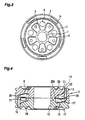
- the first piston half 5 in this embodiment does not have the sub-passages 9 and the sub-seat portion 12.
- the first piston half 5 has communication grooves 25 (sub-passages) formed on a surface thereof at which the first piston half 5 is joined to the second piston half 6, in place of the sub-passages 9.
- the communication grooves 25 communicate between the main passages 8 and the inlet passages 10, which are alternately disposed in the circumferential direction.
- the first piston half 5 further has arcuate support portions 26 projecting from the upper end surface thereof at the inner peripheral side of the seat portion 11, in place of the sub-seat portion 12, to support the compression-side main disk valve 19 against the pressure in the cylinder upper chamber A.
- the second piston half 6 is provided with communication grooves 27 (sub-passages) and support portions 28 in the same way as the first piston half 5.
- the communication grooves 25 of the first piston half 5 are not visible in Fig. 5 , but they are arranged in the same way as the communication grooves 27 of the second piston half 6.
- the support portions 28 of the second piston half 6 are not visible in Fig. 5 , but they are arranged in the same way as the support portions 26 of the first piston half 5.
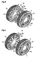
- a valve member 29 (sub-valve) is interposed between the respective surfaces of the first piston half 5 and the second piston half 6 where the first and second piston halves 5 and 6 are joined together.
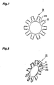
- the valve member 29 has, as shown in Figs. 7 and 8 , an annular clamped portion 29A clamped between the first and second piston halves 5 and 6 and a plurality of valve portions (including plate portions 30 and valves 31 and 32) radially extending from the clamped portion 29A to cover the communication grooves 25 and 27.
- Each valve portion has a plate portion 30 and a pair of valves 31 and 32 formed from circumferentially opposite end portions of the plate portion 30 that are bent at right angles in mutually opposite directions.
- the valve 31 closes one end of the associated communication groove 27, and the valve 32 closes one end of the associated communication groove 25. More specifically, as shown in Figs. 5 and 6 , the lower surfaces of the plate portions 30 (i.e. the surfaces closer to the second piston half 6) cover the communication grooves 27, and the valves 31 control the flow of hydraulic fluid in the communication grooves 27. On the other hand, the upper surfaces of the plate portions 30 (i.e. the surfaces closer to the first piston half 5) cover the communication grooves 25, and the valves 32 control the flow of hydraulic fluid in the communication grooves 25.
- the valves 31 and 32 operate as check valves that selectively open and close the communication grooves 27 and 25, respectively, and also function as pressure control valves that deflect to open upon receiving the pressures of hydraulic fluid in the communication grooves 27 and 25.
- the valves 31 and 32 control the flow path areas of the communication grooves 27 and 25 according to the degree of opening thereof.
- the extension-side passage C and the compression-side passage D are communicated with each other by the communication grooves 25 and 27, and the flow path areas thereof are controlled according to the degree of opening of the valves 31 and 32.
- damping force is generated by the extension-side main disk valve 21 (orifice 21A) and the compression-side main disk valve 19 (orifice 19A) in response to the extension and contraction of the piston rod 3 in the same way as in the first embodiment.
- the valves 31 and 32 open in the high piston speed region, thereby allowing the extension-side passage C and the compression-side passage D to communicate with each other through the communication grooves 25 and 27, and thus bypassing the extension-side main disk valve 21 and the compression-side main disk valve 19.
- the hydraulic fluid in the cylinder upper chamber A flows into the cylinder lower chamber B through the extension-side passage C (formed from the inlet passages 10 and the main passages 14).
- a part of the hydraulic fluid flowing through the extension-side passage C passes through the communication grooves 25 and 27 and opens the valves 32 and 31 to flow into the compression-side passage D (formed from the main passages 8 and the inlet passages 16).
- a part of hydraulic fluid in each main passage 14 flows into the inlet passages 16 at both sides of the main passage 14 through the upper side (communication groove 25) and lower side (communication groove 27) of the plate portion 30.
- the extension-side passage C and the compression-side passage D communicate with each other.
- the second embodiment enables the damping force in the high piston speed region to be reduced according to the degree of opening of the valves 31 and 32.
- damping force characteristics can be set without modifying either of the first and second piston halves 5 and 6 by properly selectively employing a valve member 29 having valves 31 and 32 of various flexibility characteristics. It is also possible to adjust damping force characteristics by differently setting valve opening characteristics (valve characteristics) of the valves 31 and 32 with respect to the communication grooves 25 and 27,
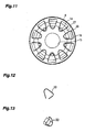
- valve members 33 in place of the valve member 29.
- Each valve member 33 is, as shown in Figs. 12 and 13 , a leaf spring member bent in a substantially C-shape (in this embodiment, it is substantially triangular to conform to the shape of the associated fitting portion).
- the valve members 33 are fitted into the joint surface-side openings of the main passages 8 of the first piston half 5 and those of the inlet passages 16 of the second piston half 6.
- Each valve member 33 selectively opens and closes the associated communication grooves 25 and 27 by one end portion thereof.
- this modification operates as follows.
- the hydraulic fluid in the cylinder upper chamber A flows into the cylinder lower chamber B through the extension-side passage C (formed from the inlet passages 10 and the main passages 14).
- a part of the hydraulic fluid flowing through the extension-side passage C passes through the communication grooves 25 and 27 and opens the one end portion of each valve member 33 to flow into the compression-side passage D (formed from the main passages 8 and the inlet passages 16).
- a part of hydraulic fluid in each main passage 14 flows into the inlet passage 16 counterclockwise adjacent to the main passage 14 through the communication grooves 25 and 27.
- valve members 33 are fitted into the main passages 8 of the first piston half 5 and the inlet passages 16 of the second piston half 6, the valve members 33 may be fitted into the inlet passages 10 of the first piston half 5 and the main passages 14 of the second piston half 6.
- the hydraulic fluid in the cylinder lower chamber B flows into the cylinder upper chamber A through the compression-side passage D (formed from the inlet passages 16 and the main passages 8).
- a part of the hydraulic fluid flowing through the compression-side passage D passes through the communication grooves 25 and 27 and opens the one end portion of each valve member 33 to flow into the extension-side passage C (formed from the main passages 14 and the inlet passages 10).
- the compression-side passage D and the extension-side passage C communicate with each other, and the damping force in the high piston speed region can be reduced according to the degree of opening of the valve members 33.
- valve members 33 operate in the same way as the valve member 29 in the second embodiment. That is, the valve members 33 operate as check valves that selectively open and close the communication grooves 25 and 27, and also function as pressure control valves that deflect to open upon receiving the pressures of hydraulic fluid in the communication grooves 25 and 27.
- the valve members 33 control the flow path areas of the communication grooves 25 and 27 according to the degree of opening thereof.
- the modification offers advantageous effects similar to those in the second embodiment.
- valve members 33 seat and unseat when closing and opening the communication grooves 25 and 27 may be made of a synthetic resin material in view of sealing performance and silent operation.
- the present invention is applied to the piston, by way of example.
- the present invention is not necessarily limited to the piston but may be similarly applied, for example as shown in Fig. 18 , to the base valve 1f (partition member) that divides the inside of the cylinder 1a and the reservoir 1g from each other.
- the present invention is also similarly applicable to a hydraulic shock absorber having, as shown in Fig. 19 , a damping force generating mechanism 1h provided outside the cylinder 1a. More specifically, the present invention is applicable to a partition member 1j that forms a hydraulic fluid passage in the damping force generating mechanism 1h.
- the present invention has been described with regard to a hydraulic shock absorber that generates a damping force by controlling the flow of hydraulic oil.
- the present invention is not necessarily limited thereto but may be similarly applied to a shock absorber that generates a damping force by controlling the flow of other hydraulic fluid, e.g. a gas.
- the shock absorber according to the present invention enables the characteristics of the extension-side and compression-side valves and sub-valves to be set independently of each other, and hence makes it possible to increase the degree of freedom for setting damping force characteristics.
Landscapes
- Engineering & Computer Science (AREA)
- General Engineering & Computer Science (AREA)
- Mechanical Engineering (AREA)
- Fluid-Damping Devices (AREA)
Applications Claiming Priority (1)
| Application Number | Priority Date | Filing Date | Title |
|---|---|---|---|
| JP2007172985A JP2009014012A (ja) | 2007-06-29 | 2007-06-29 | 緩衝器 |
Publications (1)
| Publication Number | Publication Date |
|---|---|
| EP2009321A2 true EP2009321A2 (de) | 2008-12-31 |
Family
ID=39791102
Family Applications (1)
| Application Number | Title | Priority Date | Filing Date |
|---|---|---|---|
| EP08011704A Withdrawn EP2009321A2 (de) | 2007-06-29 | 2008-06-27 | Stossdämpfer |
Country Status (4)
| Country | Link |
|---|---|
| US (1) | US20090000891A1 (de) |
| EP (1) | EP2009321A2 (de) |
| JP (1) | JP2009014012A (de) |
| CN (1) | CN101363495A (de) |
Cited By (1)
| Publication number | Priority date | Publication date | Assignee | Title |
|---|---|---|---|---|
| CN116745544A (zh) * | 2021-02-12 | 2023-09-12 | Kyb株式会社 | 缓冲器 |
Families Citing this family (17)
| Publication number | Priority date | Publication date | Assignee | Title |
|---|---|---|---|---|
| JP5618415B2 (ja) * | 2011-03-15 | 2014-11-05 | カヤバ工業株式会社 | ピストン |
| KR101288613B1 (ko) * | 2011-08-11 | 2013-07-22 | 주식회사 만도 | 쇽업소버의 피스톤 어셈블리 |
| KR101374875B1 (ko) * | 2011-12-30 | 2014-03-18 | 주식회사 만도 | 쇽업소버의 피스톤 어셈블리 |
| MX341907B (es) | 2012-04-23 | 2016-09-06 | Beijingwest Ind Co Ltd | Un amortiguador de suspension hidraulica con una valvula de disco flotante. |
| KR101457662B1 (ko) | 2013-03-15 | 2014-11-07 | 주식회사 만도 | 쇽업소버의 피스톤 어셈블리 |
| US9441699B2 (en) * | 2013-05-13 | 2016-09-13 | Tenneco Automotive Operating Company Inc. | Orifice disc for regulating flow in damper |
| JP2015232378A (ja) * | 2014-06-10 | 2015-12-24 | Kyb株式会社 | ショックアブソーバ |
| US9500251B2 (en) | 2014-11-25 | 2016-11-22 | Tenneco Automotive Operating Company Inc. | Shock absorber having orifice check disc |
| US9845839B2 (en) | 2016-02-18 | 2017-12-19 | Tenneco Automotive Operating Company Inc. | Shock absorber having check disc for orifice passage |
| JP2017198276A (ja) * | 2016-04-27 | 2017-11-02 | Kyb株式会社 | 減衰力調整バルブ及び緩衝器 |
| US10239376B2 (en) * | 2016-09-22 | 2019-03-26 | Beijingwest Industries Co., Ltd. | Hydraulic damper with an x-flow piston assembly |
| JP6700436B2 (ja) * | 2017-01-18 | 2020-05-27 | 日立オートモティブシステムズ株式会社 | 緩衝器 |
| KR102002607B1 (ko) * | 2017-05-24 | 2019-07-22 | 주식회사 만도 | 쇽업소버의 밸브구조 |
| IL266688B2 (en) * | 2019-05-16 | 2024-03-01 | Evco Pro 2018 Ltd | An automotive hydraulic shock absorber |
| DE102020209288A1 (de) | 2020-07-23 | 2022-01-27 | Thyssenkrupp Ag | Schwingungsdämpfer-Ventilanordnung mit schaltbarem Bypass |
| US11788621B2 (en) * | 2021-11-10 | 2023-10-17 | American Axle & Manufacturing, Inc. | Piston assembly formed of interlocking piston members |
| DE102023101557A1 (de) * | 2023-01-23 | 2024-07-25 | Thyssenkrupp Ag | Rückschlagventil, Schwingungsdämpfer mit einem solchen Rückschlagventil und Verwendung eines solchen Rückschlagventils |
Citations (2)
| Publication number | Priority date | Publication date | Assignee | Title |
|---|---|---|---|---|
| JP2005188602A (ja) | 2003-12-25 | 2005-07-14 | Hitachi Ltd | ピストン構造体 |
| JP2007172985A (ja) | 2005-12-21 | 2007-07-05 | Toyota Central Res & Dev Lab Inc | 水系リチウム二次電池 |
-
2007
- 2007-06-29 JP JP2007172985A patent/JP2009014012A/ja active Pending
-
2008
- 2008-06-26 US US12/213,949 patent/US20090000891A1/en not_active Abandoned
- 2008-06-27 EP EP08011704A patent/EP2009321A2/de not_active Withdrawn
- 2008-06-30 CN CNA2008101611967A patent/CN101363495A/zh active Pending
Patent Citations (2)
| Publication number | Priority date | Publication date | Assignee | Title |
|---|---|---|---|---|
| JP2005188602A (ja) | 2003-12-25 | 2005-07-14 | Hitachi Ltd | ピストン構造体 |
| JP2007172985A (ja) | 2005-12-21 | 2007-07-05 | Toyota Central Res & Dev Lab Inc | 水系リチウム二次電池 |
Cited By (2)
| Publication number | Priority date | Publication date | Assignee | Title |
|---|---|---|---|---|
| CN116745544A (zh) * | 2021-02-12 | 2023-09-12 | Kyb株式会社 | 缓冲器 |
| CN116745544B (zh) * | 2021-02-12 | 2026-07-17 | Kyb株式会社 | 缓冲器 |
Also Published As
| Publication number | Publication date |
|---|---|
| CN101363495A (zh) | 2009-02-11 |
| JP2009014012A (ja) | 2009-01-22 |
| US20090000891A1 (en) | 2009-01-01 |
Similar Documents
| Publication | Publication Date | Title |
|---|---|---|
| US20090000891A1 (en) | Shock absorber | |
| US6817454B2 (en) | Damping force control type hydraulic shock absorber | |
| KR102588959B1 (ko) | 완충기 | |
| US8590680B2 (en) | Shock absorber | |
| KR100253850B1 (ko) | 감쇠력 조정식 유압 완충기 | |
| US5934421A (en) | Damping force control type hydraulic shock absorber | |
| US7458448B2 (en) | Hydraulic shock absorber | |
| JP4055023B2 (ja) | 減衰力調整式油圧緩衝器 | |
| US7703586B2 (en) | Four-piece piston | |
| US11199241B2 (en) | Damper | |
| US20090260938A1 (en) | Shock absorber | |
| JPH10141416A5 (de) | ||
| JP2026040759A (ja) | 緩衝器 | |
| JP2012140981A (ja) | 減衰力調整式緩衝器 | |
| CN116917641A (zh) | 阀门及缓冲器 | |
| US7172057B2 (en) | Vibration damper with amplitude-dependent damping force | |
| US12031605B2 (en) | Shock absorber | |
| JP6408813B2 (ja) | 緩衝器 | |
| US20230272835A1 (en) | Shock absorber | |
| JP4356016B2 (ja) | 油圧緩衝器 | |
| CN101793303A (zh) | 缓冲器 | |
| US20240369123A1 (en) | Shock absorber | |
| US20050061592A1 (en) | Vibration damper with stroke-dependent damping force | |
| JP5307739B2 (ja) | 緩衝器のバルブ構造 | |
| JP7829452B2 (ja) | 緩衝器 |
Legal Events
| Date | Code | Title | Description |
|---|---|---|---|
| PUAI | Public reference made under article 153(3) epc to a published international application that has entered the european phase |
Free format text: ORIGINAL CODE: 0009012 |
|
| AK | Designated contracting states |
Kind code of ref document: A2 Designated state(s): AT BE BG CH CY CZ DE DK EE ES FI FR GB GR HR HU IE IS IT LI LT LU LV MC MT NL NO PL PT RO SE SI SK TR |
|
| AX | Request for extension of the european patent |
Extension state: AL BA MK RS |
|
| STAA | Information on the status of an ep patent application or granted ep patent |
Free format text: STATUS: THE APPLICATION HAS BEEN WITHDRAWN |
|
| 18W | Application withdrawn |
Effective date: 20100127 |