EP2009335B1 - Verteilungsblock für Flüssigkeiten - Google Patents
Verteilungsblock für Flüssigkeiten Download PDFInfo
- Publication number
- EP2009335B1 EP2009335B1 EP08011459A EP08011459A EP2009335B1 EP 2009335 B1 EP2009335 B1 EP 2009335B1 EP 08011459 A EP08011459 A EP 08011459A EP 08011459 A EP08011459 A EP 08011459A EP 2009335 B1 EP2009335 B1 EP 2009335B1
- Authority
- EP
- European Patent Office
- Prior art keywords
- distribution block
- openings
- circuit
- fluid
- closed
- Prior art date
- Legal status (The legal status is an assumption and is not a legal conclusion. Google has not performed a legal analysis and makes no representation as to the accuracy of the status listed.)
- Not-in-force
Links
- 239000012530 fluid Substances 0.000 title claims description 30
- 239000012528 membrane Substances 0.000 claims abstract description 16
- 238000009434 installation Methods 0.000 claims description 15
- 238000010438 heat treatment Methods 0.000 claims description 14
- 238000004378 air conditioning Methods 0.000 claims description 6
- 238000012986 modification Methods 0.000 claims description 4
- 230000004048 modification Effects 0.000 claims description 4
- 238000006073 displacement reaction Methods 0.000 claims description 2
- 238000004146 energy storage Methods 0.000 claims description 2
- 238000005259 measurement Methods 0.000 claims description 2
- 230000007797 corrosion Effects 0.000 description 2
- 238000005260 corrosion Methods 0.000 description 2
- XLYOFNOQVPJJNP-UHFFFAOYSA-N water Substances O XLYOFNOQVPJJNP-UHFFFAOYSA-N 0.000 description 2
- 238000001816 cooling Methods 0.000 description 1
- 239000013529 heat transfer fluid Substances 0.000 description 1
- 238000012423 maintenance Methods 0.000 description 1
- 238000004519 manufacturing process Methods 0.000 description 1
- 239000000463 material Substances 0.000 description 1
- 230000001105 regulatory effect Effects 0.000 description 1
Images


Classifications
-
- F—MECHANICAL ENGINEERING; LIGHTING; HEATING; WEAPONS; BLASTING
- F16—ENGINEERING ELEMENTS AND UNITS; GENERAL MEASURES FOR PRODUCING AND MAINTAINING EFFECTIVE FUNCTIONING OF MACHINES OR INSTALLATIONS; THERMAL INSULATION IN GENERAL
- F16K—VALVES; TAPS; COCKS; ACTUATING-FLOATS; DEVICES FOR VENTING OR AERATING
- F16K7/00—Diaphragm valves or cut-off apparatus, e.g. with a member deformed, but not moved bodily, to close the passage ; Pinch valves
- F16K7/12—Diaphragm valves or cut-off apparatus, e.g. with a member deformed, but not moved bodily, to close the passage ; Pinch valves with flat, dished, or bowl-shaped diaphragm
- F16K7/14—Diaphragm valves or cut-off apparatus, e.g. with a member deformed, but not moved bodily, to close the passage ; Pinch valves with flat, dished, or bowl-shaped diaphragm arranged to be deformed against a flat seat
- F16K7/17—Diaphragm valves or cut-off apparatus, e.g. with a member deformed, but not moved bodily, to close the passage ; Pinch valves with flat, dished, or bowl-shaped diaphragm arranged to be deformed against a flat seat the diaphragm being actuated by fluid pressure
-
- F—MECHANICAL ENGINEERING; LIGHTING; HEATING; WEAPONS; BLASTING
- F16—ENGINEERING ELEMENTS AND UNITS; GENERAL MEASURES FOR PRODUCING AND MAINTAINING EFFECTIVE FUNCTIONING OF MACHINES OR INSTALLATIONS; THERMAL INSULATION IN GENERAL
- F16K—VALVES; TAPS; COCKS; ACTUATING-FLOATS; DEVICES FOR VENTING OR AERATING
- F16K27/00—Construction of housing; Use of materials therefor
- F16K27/003—Housing formed from a plurality of the same valve elements
Definitions
- the invention relates to a heating and / or air conditioning circuit comprising a fluid distribution block.
- the present invention is proposed for an application of distribution of a heat transfer fluid in a domestic heating installation using several energy sources.
- the present invention relates to a heating and / or air conditioning circuit comprising a distribution block as presented in claim 1.
- a distribution block according to the invention comprises an inlet 1 and an outlet 2 for at least one fluid, in an advantageous embodiment and described hereinafter the fluid is water and the external circuit connected to the distribution block between the inlet 1 and the outlet 2 is named circuit of employment, this circuit being in the present example a domestic heating and / or air conditioning circuit to a dwelling.
- the distribution block is characterized in that it has a flexible membrane 3 disposed between a cover 4 and a base 5 pierced with orifices 6, said orifices 6 being interconnected by channels shaped in the base and connected to each other. according to the arrangement and the open or closed position of shutters positioned in said channels.
- the lid 4 and the membrane 3 are flat and fit perfectly with the upper part of the base 5 to prevent fluid leakage.
- At least one fluid inlet in the distributor corresponds to the fluid in return of a heat exchange system, forming a closed circuit for use on said distribution block, so in the advantageous example describes the circuit heating or cooling of the house.
- the distribution block allows the use of different sources.
- the distribution block comprises, in addition to the connection with the circuit for use, at least two orifices 6 connected to a closed source circuit on said distribution block, said source circuit being connected to an energy source generating or absorbing heat. or an energy storage device.
- the orifices 6 are made through the base 5, they open into the channels.
- the open channels are positioned on the upper part of the base 5 closed by the membrane 3.
- the distribution block comprises orifices connected to at least two independent source circuits closed on said distribution block and allowing the use circuit to operate in relation to at least two different energy sources selected by the distribution block.
- the domestic heating application can operate with different energy sources, it is for example possible to realize different circuits connected and closed on the distribution block, including a heater circuit, an evaporator exchanger circuit, a condenser exchanger circuit, a circuit connected to a solar collector, a geothermal circuit, a cold accumulator circuit or a heat accumulator circuit.
- All circuits to heat or cool the home and store calories if necessary. All circuits are independent and connected to the residential internal circuit by the distribution block so as to be used according to the needs of the moment.
- the management of the assembly being regulated by an automaton connected to the distribution block for the distribution of the fluid through the various circuits, which automaton performs the regulation according to measurements coming from temperature, pressure and flow sensors placed in the distribution block and / or on the circuits.
- the base 5 is shaped with a set of channels, which channels open on orifices 6 connected to the various circuits previously described.
- the channels comprise shutters allowing the flow of fluid inside the distribution block in a configuration determined by the controller and programmed in the device.
- the distribution block shown comprises a flexible membrane 3 disposed between a cover 4 and a base 5 pierced with two orifices 6, said orifices 6 being interconnected by channels 7 shaped in the base and connected in the open or closed position. shutter 8 positioned between the channels 7.
- the shutters are of substantially concave upper shape forming a cavity 11 for circulating in depression with respect to the membrane 3 pierced by at least two lumens 9, each of the lumens 9 being in relation with a part of a channel 7, so that when the upper parts of the lights are closed the fluid can no longer circulate in the channel.
- the upper parts of the apertures are closed off by means of the displacement of the overlying membrane 3, which membrane is displaced under the action of an external pressure so as to match the shape of the circulation cavity.
- the distribution block according to the invention comprises a plurality of source circuits and therefore several shutters for distributing the fluid and orienting it towards the circuit of use, according to the invention each shutter is individually adjustable and controlled in opening or closing by an automat.
- each circuit the fluid can flow in one direction or another depending on the pressures applied on each side of the shutter, the external pressure control 10 functioning as a switch passage.
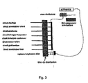
- the figure 3 illustrates different conceivable source circuits connected to the heating circuit through the distribution block, managed by the PLC and operating thanks to the information collected by temperature and flow rate sensors.
- the shutter comprises at least two lumens, one on each side of the channel, advantageously, and as illustrated in FIG. figure 2 each shutter may comprise six slots 9 for the connection between the two parts of the channel 7 and the circulation cavity, three on each side of the channel, each shutter being formed in the actual structure of the base 5 of the distribution block.
- the shutter can be shaped in the same structure of the base or reported after creation of the base and channels, according to an important variant of the invention the shutters are inserts 12, preferably removable so as to allow subsequent modifications of circulation inside the distribution block.
- FIG. 4 Such a distribution block comprising shutters inserts is shown on the figure 4 .
- This figure 4 showing a dispenser with 14 orifices and 11 shutters for connecting the circuits described in figure 3 .
- distribution block Several variants of the distribution block are possible, different configurations of channels shaped in the base can be arranged, the number of circuits that can be made and connectable to the distribution block can be high and very variable depending on the applications envisaged without departing from the scope of the invention.
- a variable number of shutters can be arranged, having different configurations of lights for the passage of fluid, without departing from the scope of the invention.
- the distribution block is mainly intended for the circulation of water in a domestic heating installation, however there is no prohibition to use another fluid, with a suitable membrane, for other applications including industrial.
- the distribution block operates mainly with a single fluid conveyed in different circuits however it can be envisaged, without departing from the scope of the invention, to pass through the distribution block several different fluids with separate external circuits.
- the distribution block is feasible in different materials, different modes of manufacture of the base and shutters are feasible, and the entire distribution block can be provided hermetically sealed, or advantageously removable, without departing from the scope of the invention.
Landscapes
- Engineering & Computer Science (AREA)
- General Engineering & Computer Science (AREA)
- Mechanical Engineering (AREA)
- Physics & Mathematics (AREA)
- Fluid Mechanics (AREA)
- Separation Using Semi-Permeable Membranes (AREA)
- External Artificial Organs (AREA)
- Steam Or Hot-Water Central Heating Systems (AREA)
Claims (8)
- Heiz- und/oder Klimatisierungskreis, der einen Verteilerblock mit wenigstens einem Einlass (1) und einem Auslass (2) für wenigstens ein Fluid aufweist, der über eine elastische Membran (3) verfügt, die zwischen einer Abdeckung (4) und einem mit Öffnungen (6) versehenen Grundteil (5) angeordnet ist, wobei die Öffnungen (6) untereinander mit Kanälen (7) verbunden sind, die in dem Grundteil (5) eingeformt sind und entsprechend der geöffneten oder geschlossenen Stellung von in den Kanälen (7) angeordneten Verschlussteilen (8) verbunden werden, wobei die Öffnungen (6) außen an wenigstens einen Kreis angeschlossen sind, dadurch gekennzeichnet, dass wenigstens ein Fluideinlass (1) in den Verteilerblock dem aus einer Wärmeaustauschvorrichtung zurückkehrenden Fluid zugeordnet ist, wobei ein geschlossener Betriebskreis mit dem Verteilerblock gebildet ist, und dass der Verteilerblock weiterhin über wenigstens zwei Öffnungen (6) verfügt, die an einen geschlossenen Quellkreis unter Einschluss des Verteilerblocks angeschlossen sind, wobei der Quellkreis mit einer Wärme erzeugenden oder absorbierenden Energiequelle oder mit einer Energiespeichervorrichtung verbunden ist.
- Kreis nach Anspruch 1, der Öffnungen (6) aufweist, die an wenigstens zwei unabhängige geschlossene Quellkreise unter Einschluss des Verteilerblocks angeschlossen sind, und der dem Betriebskreis erlaubt, in Verbindung mit wenigstens zwei unterschiedlichen Energiequellen zu arbeiten, die von dem Verteilerblock ausgewählt sind.
- Kreis nach Anspruch 2, bei dem jedes Verschlussteil (8) eine im Wesentlichen konkav ausgebildete Oberfläche aufweist, um eine Zirkulationsvertiefung (11) für das Fluid zu bilden, die in Bezug auf die Membran (3) vertieft angeordnet ist, wobei die Vertiefung (11) mit wenigstens zwei Schlitzen (9) versehen ist und wobei jeder Teil des Kanals (7) auf jeder Seite eines Verschlussteils (8) mit der Zirkulationsvertiefung (11) über wenigstens einen Schlitz (9) verbunden ist, so dass, wenn die oberen Teile der in der Vertiefung (11) angeordneten Schlitze (9) verschlossen sind, das Fluid in dem Kanal (7) nicht mehr zirkulieren kann.
- Kreis nach Anspruch 3, bei dem die oberen Teile der Schlitze (9) durch das Verschieben der darüber angeordneten Membran (3) verschlossen sind, wobei die Membran (3) durch die Wirkung eines äußeren Drucks (10) verschoben ist, um sich an die Gestalt der Zirkulationsvertiefung (11) anzupassen.
- Kreis nach Anspruch 4, bei dem jedes Verschlussteil (8) einzeln einstellbar und beim Öffnen oder Schließen durch einen Automatismus steuerbar ist.
- Kreis nach Anspruch 5, bei dem der Automat den Verteilerblock bei der Verteilung des Fluids über die verschiedenen Kreise in Abhängigkeit von den Messungen leitet, die von Temperatur-, Druck- und Durchflussfühlern eingehen.
- Kreis nach Anspruch 6, bei dem jedes Verschlussteil (8) über sechs Schlitze (9) verfügt, um eine Verbindung zwischen den beiden Teilen des Kanals (7) und der Zirkulationsvertiefung (11) zu schaffen, wobei drei Schlitze auf jeder Seite des Kanals (7) angeordnet sind und jedes Verschlussteil (8) in der Struktur des Grundteils (5) des Verteilerblocks ausgebildet ist.
- Kreis nach Anspruch 6, bei dem die Verschlussteile bevorzugterweise lösbare Einsätze (12) sind, um spätere Veränderungen der Zirkulation des Fluids im Inneren des Verteilerblocks und verschiedene Kreiskonfigurationen zu erlauben.
Applications Claiming Priority (1)
| Application Number | Priority Date | Filing Date | Title |
|---|---|---|---|
| FR0756144A FR2918148A1 (fr) | 2007-06-29 | 2007-06-29 | Bloc de distribution de fluides. |
Publications (3)
| Publication Number | Publication Date |
|---|---|
| EP2009335A2 EP2009335A2 (de) | 2008-12-31 |
| EP2009335A3 EP2009335A3 (de) | 2009-07-29 |
| EP2009335B1 true EP2009335B1 (de) | 2011-10-26 |
Family
ID=39047884
Family Applications (1)
| Application Number | Title | Priority Date | Filing Date |
|---|---|---|---|
| EP08011459A Not-in-force EP2009335B1 (de) | 2007-06-29 | 2008-06-25 | Verteilungsblock für Flüssigkeiten |
Country Status (3)
| Country | Link |
|---|---|
| EP (1) | EP2009335B1 (de) |
| AT (1) | ATE530823T1 (de) |
| FR (1) | FR2918148A1 (de) |
Families Citing this family (1)
| Publication number | Priority date | Publication date | Assignee | Title |
|---|---|---|---|---|
| WO2015089202A1 (en) | 2013-12-10 | 2015-06-18 | Semba Biosciences, Inc. | High-flow fluid valve block |
Family Cites Families (5)
| Publication number | Priority date | Publication date | Assignee | Title |
|---|---|---|---|---|
| US3094144A (en) * | 1960-01-13 | 1963-06-18 | Le Roy V Oxley | Vacuum actuated blocking valve for vacuum controlled mechanism |
| US3156157A (en) * | 1961-04-11 | 1964-11-10 | Burroughs Corp | Positioning control system and apparatus |
| US4119120A (en) * | 1976-11-29 | 1978-10-10 | Beckman Instruments, Inc. | Fluid switch |
| US4917348A (en) * | 1988-11-14 | 1990-04-17 | Oden Corporation | Filling nozzle cut-off valve |
| US5176359A (en) * | 1991-05-20 | 1993-01-05 | Photovac International, Inc. | Fluid control valve arrangement |
-
2007
- 2007-06-29 FR FR0756144A patent/FR2918148A1/fr not_active Withdrawn
-
2008
- 2008-06-25 EP EP08011459A patent/EP2009335B1/de not_active Not-in-force
- 2008-06-25 AT AT08011459T patent/ATE530823T1/de not_active IP Right Cessation
Also Published As
| Publication number | Publication date |
|---|---|
| EP2009335A3 (de) | 2009-07-29 |
| FR2918148A1 (fr) | 2009-01-02 |
| ATE530823T1 (de) | 2011-11-15 |
| EP2009335A2 (de) | 2008-12-31 |
Similar Documents
| Publication | Publication Date | Title |
|---|---|---|
| KR101339250B1 (ko) | 차량용 열교환기 | |
| US8191549B2 (en) | Tube collector with variable thermal conductivity of the coaxial tube | |
| EP3931507B1 (de) | Temperaturregelvorrichtung, insbesondere eine kühlvorrichtung für ein kraftfahrzeug | |
| EP2232155B1 (de) | Anlage zur bereitstellung von hygienischem warmwasser für mehrfamilienhäuser | |
| WO2020212457A1 (fr) | Dispositif de régulation thermique, notamment de refroidissement pour véhicule automobile | |
| FR2988460A1 (fr) | Vanne a six voies a element rotatif pour l'obturation selective, et installation de chauffage/climatisation associee | |
| EP2009335A2 (de) | Verteilungsblock für Flüssigkeiten | |
| FR3013823A1 (fr) | Echangeur air/air a double flux, installation de traitement d'air et methode de nettoyage d'un tel echangeur | |
| EP2306096B1 (de) | Heizsystem für Brauchwasser und Raumheizung mit zwei Wärmequellen | |
| FR2790073A1 (fr) | Echangeur thermique a plaques, a vanne integree | |
| EP2085705A2 (de) | Kombinierte Klimaanlagenvorrichtung | |
| EP3250810B1 (de) | Luftansaugsystem und ansaugluftwärmeverwaltungsverfahren | |
| FR2803025A1 (fr) | Echangeur thermique a plaques, a clapet de decharge integre | |
| EP2743601B1 (de) | Kompaktes Innenmodul für Wärmregulierungsanlage mit Wärmepumpe | |
| FR2913755A1 (fr) | Dispositif de ventilation pour echangeur thermique | |
| FR2846407A1 (fr) | Echangeur de chaleur a regulation de flux, en particulier pour vehicules automobiles | |
| FR2958729A3 (fr) | Module de pompe destine a servir dans un collecteur pour systeme de chauffage par le sol | |
| EP1067351B1 (de) | Heizkörper | |
| WO2012150359A2 (fr) | Installation thermique | |
| EP0604308B1 (de) | Wärmetauscher und Anwendung zur Kühlung von Milch aus einer Melkanlage | |
| BE1032004B1 (fr) | Élément distributeur de dispositif récupérateur de chaleur | |
| EP2770288B1 (de) | System zur Speicherung und Entnahme von Wärmeenergie, die in einem Fluid enthalten ist | |
| EP1507122A1 (de) | Kombinierte Anlage für Zentralheizung und Brauchwasserheizung | |
| EP3722703A1 (de) | Thermodynamische maschine vom typ wärmepumpe zum erzeugen von wärme und kälte, und ihr funktionsverfahren | |
| FR3027099A1 (fr) | Dispositif de chauffage ou climatisation d'un local pour habitation |
Legal Events
| Date | Code | Title | Description |
|---|---|---|---|
| PUAI | Public reference made under article 153(3) epc to a published international application that has entered the european phase |
Free format text: ORIGINAL CODE: 0009012 |
|
| AK | Designated contracting states |
Kind code of ref document: A2 Designated state(s): AT BE BG CH CY CZ DE DK EE ES FI FR GB GR HR HU IE IS IT LI LT LU LV MC MT NL NO PL PT RO SE SI SK TR |
|
| AX | Request for extension of the european patent |
Extension state: AL BA MK RS |
|
| PUAL | Search report despatched |
Free format text: ORIGINAL CODE: 0009013 |
|
| AK | Designated contracting states |
Kind code of ref document: A3 Designated state(s): AT BE BG CH CY CZ DE DK EE ES FI FR GB GR HR HU IE IS IT LI LT LU LV MC MT NL NO PL PT RO SE SI SK TR |
|
| AX | Request for extension of the european patent |
Extension state: AL BA MK RS |
|
| 17P | Request for examination filed |
Effective date: 20100129 |
|
| AKX | Designation fees paid |
Designated state(s): AT BE BG CH CY CZ DE DK EE ES FI FR GB GR HR HU IE IS IT LI LT LU LV MC MT NL NO PL PT RO SE SI SK TR |
|
| GRAP | Despatch of communication of intention to grant a patent |
Free format text: ORIGINAL CODE: EPIDOSNIGR1 |
|
| RIN1 | Information on inventor provided before grant (corrected) |
Inventor name: DELAITE, ERIC Inventor name: DELAITE, JEAN-FRANCOIS Inventor name: DELAITE, ARNAUD |
|
| GRAS | Grant fee paid |
Free format text: ORIGINAL CODE: EPIDOSNIGR3 |
|
| GRAA | (expected) grant |
Free format text: ORIGINAL CODE: 0009210 |
|
| AK | Designated contracting states |
Kind code of ref document: B1 Designated state(s): AT BE BG CH CY CZ DE DK EE ES FI FR GB GR HR HU IE IS IT LI LT LU LV MC MT NL NO PL PT RO SE SI SK TR |
|
| REG | Reference to a national code |
Ref country code: GB Ref legal event code: FG4D Free format text: NOT ENGLISH |
|
| REG | Reference to a national code |
Ref country code: CH Ref legal event code: EP |
|
| REG | Reference to a national code |
Ref country code: IE Ref legal event code: FG4D |
|
| REG | Reference to a national code |
Ref country code: DE Ref legal event code: R096 Ref document number: 602008010714 Country of ref document: DE Effective date: 20111222 |
|
| REG | Reference to a national code |
Ref country code: NL Ref legal event code: VDEP Effective date: 20111026 |
|
| LTIE | Lt: invalidation of european patent or patent extension |
Effective date: 20111026 |
|
| REG | Reference to a national code |
Ref country code: AT Ref legal event code: MK05 Ref document number: 530823 Country of ref document: AT Kind code of ref document: T Effective date: 20111026 |
|
| PG25 | Lapsed in a contracting state [announced via postgrant information from national office to epo] |
Ref country code: NO Free format text: LAPSE BECAUSE OF FAILURE TO SUBMIT A TRANSLATION OF THE DESCRIPTION OR TO PAY THE FEE WITHIN THE PRESCRIBED TIME-LIMIT Effective date: 20120126 Ref country code: IS Free format text: LAPSE BECAUSE OF FAILURE TO SUBMIT A TRANSLATION OF THE DESCRIPTION OR TO PAY THE FEE WITHIN THE PRESCRIBED TIME-LIMIT Effective date: 20120226 Ref country code: LT Free format text: LAPSE BECAUSE OF FAILURE TO SUBMIT A TRANSLATION OF THE DESCRIPTION OR TO PAY THE FEE WITHIN THE PRESCRIBED TIME-LIMIT Effective date: 20111026 |
|
| PG25 | Lapsed in a contracting state [announced via postgrant information from national office to epo] |
Ref country code: PL Free format text: LAPSE BECAUSE OF FAILURE TO SUBMIT A TRANSLATION OF THE DESCRIPTION OR TO PAY THE FEE WITHIN THE PRESCRIBED TIME-LIMIT Effective date: 20111026 Ref country code: PT Free format text: LAPSE BECAUSE OF FAILURE TO SUBMIT A TRANSLATION OF THE DESCRIPTION OR TO PAY THE FEE WITHIN THE PRESCRIBED TIME-LIMIT Effective date: 20120227 Ref country code: NL Free format text: LAPSE BECAUSE OF FAILURE TO SUBMIT A TRANSLATION OF THE DESCRIPTION OR TO PAY THE FEE WITHIN THE PRESCRIBED TIME-LIMIT Effective date: 20111026 Ref country code: LV Free format text: LAPSE BECAUSE OF FAILURE TO SUBMIT A TRANSLATION OF THE DESCRIPTION OR TO PAY THE FEE WITHIN THE PRESCRIBED TIME-LIMIT Effective date: 20111026 Ref country code: GR Free format text: LAPSE BECAUSE OF FAILURE TO SUBMIT A TRANSLATION OF THE DESCRIPTION OR TO PAY THE FEE WITHIN THE PRESCRIBED TIME-LIMIT Effective date: 20120127 Ref country code: HR Free format text: LAPSE BECAUSE OF FAILURE TO SUBMIT A TRANSLATION OF THE DESCRIPTION OR TO PAY THE FEE WITHIN THE PRESCRIBED TIME-LIMIT Effective date: 20111026 Ref country code: SE Free format text: LAPSE BECAUSE OF FAILURE TO SUBMIT A TRANSLATION OF THE DESCRIPTION OR TO PAY THE FEE WITHIN THE PRESCRIBED TIME-LIMIT Effective date: 20111026 Ref country code: SI Free format text: LAPSE BECAUSE OF FAILURE TO SUBMIT A TRANSLATION OF THE DESCRIPTION OR TO PAY THE FEE WITHIN THE PRESCRIBED TIME-LIMIT Effective date: 20111026 |
|
| REG | Reference to a national code |
Ref country code: IE Ref legal event code: FD4D |
|
| PG25 | Lapsed in a contracting state [announced via postgrant information from national office to epo] |
Ref country code: CY Free format text: LAPSE BECAUSE OF FAILURE TO SUBMIT A TRANSLATION OF THE DESCRIPTION OR TO PAY THE FEE WITHIN THE PRESCRIBED TIME-LIMIT Effective date: 20111026 |
|
| PG25 | Lapsed in a contracting state [announced via postgrant information from national office to epo] |
Ref country code: IE Free format text: LAPSE BECAUSE OF FAILURE TO SUBMIT A TRANSLATION OF THE DESCRIPTION OR TO PAY THE FEE WITHIN THE PRESCRIBED TIME-LIMIT Effective date: 20111026 Ref country code: BG Free format text: LAPSE BECAUSE OF FAILURE TO SUBMIT A TRANSLATION OF THE DESCRIPTION OR TO PAY THE FEE WITHIN THE PRESCRIBED TIME-LIMIT Effective date: 20120126 Ref country code: DK Free format text: LAPSE BECAUSE OF FAILURE TO SUBMIT A TRANSLATION OF THE DESCRIPTION OR TO PAY THE FEE WITHIN THE PRESCRIBED TIME-LIMIT Effective date: 20111026 Ref country code: CZ Free format text: LAPSE BECAUSE OF FAILURE TO SUBMIT A TRANSLATION OF THE DESCRIPTION OR TO PAY THE FEE WITHIN THE PRESCRIBED TIME-LIMIT Effective date: 20111026 Ref country code: EE Free format text: LAPSE BECAUSE OF FAILURE TO SUBMIT A TRANSLATION OF THE DESCRIPTION OR TO PAY THE FEE WITHIN THE PRESCRIBED TIME-LIMIT Effective date: 20111026 Ref country code: SK Free format text: LAPSE BECAUSE OF FAILURE TO SUBMIT A TRANSLATION OF THE DESCRIPTION OR TO PAY THE FEE WITHIN THE PRESCRIBED TIME-LIMIT Effective date: 20111026 |
|
| PG25 | Lapsed in a contracting state [announced via postgrant information from national office to epo] |
Ref country code: RO Free format text: LAPSE BECAUSE OF FAILURE TO SUBMIT A TRANSLATION OF THE DESCRIPTION OR TO PAY THE FEE WITHIN THE PRESCRIBED TIME-LIMIT Effective date: 20111026 Ref country code: IT Free format text: LAPSE BECAUSE OF FAILURE TO SUBMIT A TRANSLATION OF THE DESCRIPTION OR TO PAY THE FEE WITHIN THE PRESCRIBED TIME-LIMIT Effective date: 20111026 |
|
| PLBE | No opposition filed within time limit |
Free format text: ORIGINAL CODE: 0009261 |
|
| STAA | Information on the status of an ep patent application or granted ep patent |
Free format text: STATUS: NO OPPOSITION FILED WITHIN TIME LIMIT |
|
| 26N | No opposition filed |
Effective date: 20120727 |
|
| REG | Reference to a national code |
Ref country code: DE Ref legal event code: R097 Ref document number: 602008010714 Country of ref document: DE Effective date: 20120727 |
|
| BERE | Be: lapsed |
Owner name: WITECK Effective date: 20120630 |
|
| PG25 | Lapsed in a contracting state [announced via postgrant information from national office to epo] |
Ref country code: AT Free format text: LAPSE BECAUSE OF FAILURE TO SUBMIT A TRANSLATION OF THE DESCRIPTION OR TO PAY THE FEE WITHIN THE PRESCRIBED TIME-LIMIT Effective date: 20111026 Ref country code: MC Free format text: LAPSE BECAUSE OF NON-PAYMENT OF DUE FEES Effective date: 20120630 |
|
| REG | Reference to a national code |
Ref country code: CH Ref legal event code: PL |
|
| REG | Reference to a national code |
Ref country code: CH Ref legal event code: PL |
|
| GBPC | Gb: european patent ceased through non-payment of renewal fee |
Effective date: 20120625 |
|
| REG | Reference to a national code |
Ref country code: DE Ref legal event code: R119 Ref document number: 602008010714 Country of ref document: DE Effective date: 20130101 |
|
| PG25 | Lapsed in a contracting state [announced via postgrant information from national office to epo] |
Ref country code: CH Free format text: LAPSE BECAUSE OF NON-PAYMENT OF DUE FEES Effective date: 20120630 Ref country code: DE Free format text: LAPSE BECAUSE OF NON-PAYMENT OF DUE FEES Effective date: 20130101 Ref country code: LI Free format text: LAPSE BECAUSE OF NON-PAYMENT OF DUE FEES Effective date: 20120630 Ref country code: ES Free format text: LAPSE BECAUSE OF FAILURE TO SUBMIT A TRANSLATION OF THE DESCRIPTION OR TO PAY THE FEE WITHIN THE PRESCRIBED TIME-LIMIT Effective date: 20120206 Ref country code: BE Free format text: LAPSE BECAUSE OF NON-PAYMENT OF DUE FEES Effective date: 20120630 Ref country code: GB Free format text: LAPSE BECAUSE OF NON-PAYMENT OF DUE FEES Effective date: 20120625 |
|
| PG25 | Lapsed in a contracting state [announced via postgrant information from national office to epo] |
Ref country code: FI Free format text: LAPSE BECAUSE OF FAILURE TO SUBMIT A TRANSLATION OF THE DESCRIPTION OR TO PAY THE FEE WITHIN THE PRESCRIBED TIME-LIMIT Effective date: 20111026 |
|
| PG25 | Lapsed in a contracting state [announced via postgrant information from national office to epo] |
Ref country code: MT Free format text: LAPSE BECAUSE OF FAILURE TO SUBMIT A TRANSLATION OF THE DESCRIPTION OR TO PAY THE FEE WITHIN THE PRESCRIBED TIME-LIMIT Effective date: 20111026 |
|
| PG25 | Lapsed in a contracting state [announced via postgrant information from national office to epo] |
Ref country code: TR Free format text: LAPSE BECAUSE OF FAILURE TO SUBMIT A TRANSLATION OF THE DESCRIPTION OR TO PAY THE FEE WITHIN THE PRESCRIBED TIME-LIMIT Effective date: 20111026 |
|
| PG25 | Lapsed in a contracting state [announced via postgrant information from national office to epo] |
Ref country code: LU Free format text: LAPSE BECAUSE OF NON-PAYMENT OF DUE FEES Effective date: 20120625 |
|
| PG25 | Lapsed in a contracting state [announced via postgrant information from national office to epo] |
Ref country code: HU Free format text: LAPSE BECAUSE OF FAILURE TO SUBMIT A TRANSLATION OF THE DESCRIPTION OR TO PAY THE FEE WITHIN THE PRESCRIBED TIME-LIMIT Effective date: 20080625 |
|
| REG | Reference to a national code |
Ref country code: FR Ref legal event code: PLFP Year of fee payment: 8 |
|
| PGFP | Annual fee paid to national office [announced via postgrant information from national office to epo] |
Ref country code: FR Payment date: 20150622 Year of fee payment: 8 |
|
| REG | Reference to a national code |
Ref country code: FR Ref legal event code: ST Effective date: 20170228 |
|
| PG25 | Lapsed in a contracting state [announced via postgrant information from national office to epo] |
Ref country code: FR Free format text: LAPSE BECAUSE OF NON-PAYMENT OF DUE FEES Effective date: 20160630 |