EP2009346A1 - Beleuchtungsmodule für Scheinwerfer eines Kraftfahrzeugs - Google Patents
Beleuchtungsmodule für Scheinwerfer eines Kraftfahrzeugs Download PDFInfo
- Publication number
- EP2009346A1 EP2009346A1 EP08158537A EP08158537A EP2009346A1 EP 2009346 A1 EP2009346 A1 EP 2009346A1 EP 08158537 A EP08158537 A EP 08158537A EP 08158537 A EP08158537 A EP 08158537A EP 2009346 A1 EP2009346 A1 EP 2009346A1
- Authority
- EP
- European Patent Office
- Prior art keywords
- mirror
- vehicle
- folder
- lighting module
- module according
- Prior art date
- Legal status (The legal status is an assumption and is not a legal conclusion. Google has not performed a legal analysis and makes no representation as to the accuracy of the status listed.)
- Granted
Links
- 238000005520 cutting process Methods 0.000 claims description 14
- 230000003287 optical effect Effects 0.000 claims description 11
- 238000003892 spreading Methods 0.000 claims description 3
- 238000010586 diagram Methods 0.000 description 5
- 238000004519 manufacturing process Methods 0.000 description 4
- 239000013598 vector Substances 0.000 description 2
- 101100008048 Caenorhabditis elegans cut-4 gene Proteins 0.000 description 1
- 229920000297 Rayon Polymers 0.000 description 1
- 240000008042 Zea mays Species 0.000 description 1
- 238000005452 bending Methods 0.000 description 1
- 230000015572 biosynthetic process Effects 0.000 description 1
- 230000002349 favourable effect Effects 0.000 description 1
- 239000011521 glass Substances 0.000 description 1
- 238000005286 illumination Methods 0.000 description 1
- 239000000463 material Substances 0.000 description 1
- 230000007935 neutral effect Effects 0.000 description 1
- 239000004033 plastic Substances 0.000 description 1
- 239000002964 rayon Substances 0.000 description 1
- 230000001131 transforming effect Effects 0.000 description 1
- 239000012780 transparent material Substances 0.000 description 1
- 238000003466 welding Methods 0.000 description 1
Images


Classifications
-
- B—PERFORMING OPERATIONS; TRANSPORTING
- B60—VEHICLES IN GENERAL
- B60Q—ARRANGEMENT OF SIGNALLING OR LIGHTING DEVICES, THE MOUNTING OR SUPPORTING THEREOF OR CIRCUITS THEREFOR, FOR VEHICLES IN GENERAL
- B60Q1/00—Arrangement of optical signalling or lighting devices, the mounting or supporting thereof or circuits therefor
- B60Q1/0029—Spatial arrangement
- B60Q1/0035—Spatial arrangement relative to the vehicle
-
- F—MECHANICAL ENGINEERING; LIGHTING; HEATING; WEAPONS; BLASTING
- F21—LIGHTING
- F21S—NON-PORTABLE LIGHTING DEVICES; SYSTEMS THEREOF; VEHICLE LIGHTING DEVICES SPECIALLY ADAPTED FOR VEHICLE EXTERIORS
- F21S41/00—Illuminating devices specially adapted for vehicle exteriors, e.g. headlamps
- F21S41/10—Illuminating devices specially adapted for vehicle exteriors, e.g. headlamps characterised by the light source
- F21S41/14—Illuminating devices specially adapted for vehicle exteriors, e.g. headlamps characterised by the light source characterised by the type of light source
- F21S41/141—Light emitting diodes [LED]
- F21S41/147—Light emitting diodes [LED] the main emission direction of the LED being angled to the optical axis of the illuminating device
-
- F—MECHANICAL ENGINEERING; LIGHTING; HEATING; WEAPONS; BLASTING
- F21—LIGHTING
- F21S—NON-PORTABLE LIGHTING DEVICES; SYSTEMS THEREOF; VEHICLE LIGHTING DEVICES SPECIALLY ADAPTED FOR VEHICLE EXTERIORS
- F21S41/00—Illuminating devices specially adapted for vehicle exteriors, e.g. headlamps
- F21S41/10—Illuminating devices specially adapted for vehicle exteriors, e.g. headlamps characterised by the light source
- F21S41/14—Illuminating devices specially adapted for vehicle exteriors, e.g. headlamps characterised by the light source characterised by the type of light source
- F21S41/141—Light emitting diodes [LED]
- F21S41/151—Light emitting diodes [LED] arranged in one or more lines
-
- F—MECHANICAL ENGINEERING; LIGHTING; HEATING; WEAPONS; BLASTING
- F21—LIGHTING
- F21S—NON-PORTABLE LIGHTING DEVICES; SYSTEMS THEREOF; VEHICLE LIGHTING DEVICES SPECIALLY ADAPTED FOR VEHICLE EXTERIORS
- F21S41/00—Illuminating devices specially adapted for vehicle exteriors, e.g. headlamps
- F21S41/30—Illuminating devices specially adapted for vehicle exteriors, e.g. headlamps characterised by reflectors
- F21S41/32—Optical layout thereof
- F21S41/321—Optical layout thereof the reflector being a surface of revolution or a planar surface, e.g. truncated
-
- F—MECHANICAL ENGINEERING; LIGHTING; HEATING; WEAPONS; BLASTING
- F21—LIGHTING
- F21S—NON-PORTABLE LIGHTING DEVICES; SYSTEMS THEREOF; VEHICLE LIGHTING DEVICES SPECIALLY ADAPTED FOR VEHICLE EXTERIORS
- F21S41/00—Illuminating devices specially adapted for vehicle exteriors, e.g. headlamps
- F21S41/30—Illuminating devices specially adapted for vehicle exteriors, e.g. headlamps characterised by reflectors
- F21S41/32—Optical layout thereof
- F21S41/323—Optical layout thereof the reflector having two perpendicular cross sections having regular geometrical curves of a distinct nature
-
- F—MECHANICAL ENGINEERING; LIGHTING; HEATING; WEAPONS; BLASTING
- F21—LIGHTING
- F21S—NON-PORTABLE LIGHTING DEVICES; SYSTEMS THEREOF; VEHICLE LIGHTING DEVICES SPECIALLY ADAPTED FOR VEHICLE EXTERIORS
- F21S41/00—Illuminating devices specially adapted for vehicle exteriors, e.g. headlamps
- F21S41/30—Illuminating devices specially adapted for vehicle exteriors, e.g. headlamps characterised by reflectors
- F21S41/32—Optical layout thereof
- F21S41/36—Combinations of two or more separate reflectors
- F21S41/365—Combinations of two or more separate reflectors successively reflecting the light
-
- F—MECHANICAL ENGINEERING; LIGHTING; HEATING; WEAPONS; BLASTING
- F21—LIGHTING
- F21S—NON-PORTABLE LIGHTING DEVICES; SYSTEMS THEREOF; VEHICLE LIGHTING DEVICES SPECIALLY ADAPTED FOR VEHICLE EXTERIORS
- F21S41/00—Illuminating devices specially adapted for vehicle exteriors, e.g. headlamps
- F21S41/40—Illuminating devices specially adapted for vehicle exteriors, e.g. headlamps characterised by screens, non-reflecting members, light-shielding members or fixed shades
- F21S41/43—Illuminating devices specially adapted for vehicle exteriors, e.g. headlamps characterised by screens, non-reflecting members, light-shielding members or fixed shades characterised by the shape thereof
Definitions
- the plaintiff company has also filed a French patent application FR 06 03 062 April 06, 2006 , according to which a reflecting mirror located below the collecting mirror can be combined with a second reflecting mirror situated substantially above a second collecting mirror.
- the lighting modules of the state of the art, with parabolic return mirror located substantially above the collector mirror do not, to date, to obtain satisfactorily broad beams.
- the object of the invention is, above all, to provide a lighting module making it possible to obtain a wide, cut-off beam.
- the cutoff of the beam must be clear, even if the light source is inclined relative to the longitudinal axis of the vehicle, in particular in a curved projector.
- the design of the module facilitates its manufacture, in particular as regards the electrical connections of the light source, in particular when this source is constituted by light-emitting diodes or LEDs.
- the convex reflective surface of the folder makes it possible to widen the outgoing beam.
- the assembly makes it possible to create a wide outgoing beam at break.
- the folding machine has the intersection of the vertical plane of left / right symmetry of the light source and the mean plane of the source, and the generatrices of the portion of the cylinder, as the generatrix direction. forming the folder rely on said curve.
- the average plane of the source is that of the planar emitter.
- the invention also relates to a code projector comprising the minus a lighting module as defined above.
- the headlight advantageously comprises as a light source electroluminescent diodes with flat emitters which are located on the same plane, inclined horizontally with respect to the geometric axis of the vehicle.
- the plane of the emitters is inclined horizontally with respect to the transverse direction, orthogonal to the geometric axis of the vehicle, at an angle preferably of at most 45 °, for example between 2 ° and 40 °.
- the projector code is of the dynamic bending light (DBL) type and comprises orientable modules for creating a central zone of the V-cut beam, and fixed modules with a horizontal cut-off line and a width of the beam. beam sufficient to frame the central zone in the extreme steering positions.
- the projector code may include to the outside of the vehicle at least two steerable modules, and inward, three fixed modules broad beam.
- the orientable modules can for example turn about a substantially vertical axis to follow the curve of the road.
- the invention also relates to a road searchlight comprising a lighting module described above but in which the reflecting mirror is located substantially below the collector mirror when the module is in place on the vehicle.
- This road-type lighting module thus makes it possible to create a cut-out delimiting the lower portion of the light beam emitted by the lighting module. This makes it possible to improve the qualities of the road beam by avoiding an excess of near light on the road and to add an extra light in the distance.
- this road-type lighting module is associated with a code-type lighting module, according to the invention or not.
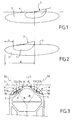
- Fig. 1 and 2 traces of light beams on a screen located at a distance from a projector and orthogonal to the axis of the beam.
- the scheme of Fig. 1 corresponds to a code beam comprising a central part 1 with more intense lighting limited by a cutting edge 2 in V whose branch on the left is substantially horizontal and the branch on the right goes up at an angle of 15 ° on the horizontal. This is a non-limiting angle value, since this angle may be more generally between 10 and 60 °.
- the beam further comprises a wider portion 3, which protrudes on the right and left of the central portion 1.
- the wide portion 3 has a horizontal flat cut 4, located at the same level as the horizontal branch of the cutoff 2. V.
- the lighting in Part 3 is less intense than in the Part 1, but sufficient for the lateral areas.
- At least the central portion 1 can rotate about a substantially vertical axis to follow the steering wheel of the vehicle.
- Fig. 2 resumes the scheme of Fig. 1 but with the central part 1 moved to the maximum to the left, due to a steering of the front wheels on the left.
- the wide part 3 of the beam has not moved angularly because, according to the invention, it can be obtained with one or more fixed modules giving a wide beam.
- the width of the beam must be sufficient so that the portion 3 overflows at least a minimum distance d relative to the central portion 1 when the latter is moved to a maximum of one side.
- the angular extent A of the wide portion 3 with respect to the longitudinal axis of the vehicle is at least 30 ° on each side of the axis, towards the outside of the vehicle.
- the extent A corresponds to the angle between the mean direction of the beam and the marginal rays.
- the flat cut line 4 must be clean.
- the light source is advantageously constituted by several light-emitting diodes, abbreviated as "LEDs", comprising planar emitters E1g, E2g, E3g, on the left side of the vehicle and E1d, E2d, E3d on the right side of the vehicle.
- the transmitters arranged on the same side of the vehicle are located on one and the same plane support Bg, or Bd. This arrangement facilitates the manufacture, including the connection and welding operations of the terminals of the different transmitters.
- the traces of plane supports Bg, Bd on a horizontal plane as illustrated on Fig. 3 and 4 are inclined at an angle ⁇ relative to the transverse direction T, orthogonal to the longitudinal axis L of the vehicle.
- the average direction ⁇ g, ⁇ d of the light beam emitted by each emitter forms an angle ⁇ with the longitudinal axis L of the vehicle.
- Fig.5 shows a lighting module Q according to the invention, with light source S formed by at least one led comprising at least one plane emitter E2g disposed on plane support Bg inclined by an angle ⁇ ( Fig. 3 ) relative to the transverse direction T of the vehicle, and an angle ⁇ with respect to the vertical direction.
- the angle ⁇ can be of the order of 40 °.
- the light source S is arranged to illuminate forwards and upwards.
- the terms “front” and “rear” are to be understood by considering the normal direction of forward movement of the vehicle equipped with the module.
- a collector mirror 6 of ellipsoidal type is arranged in front of the source S and is turned towards the rear.
- This mirror 6 comprises a first focus F1 to which, or in the vicinity of which, is disposed the center of the source S which illuminates towards the mirror 6, and a second focus F2 located on the optical axis X-X of the module.
- the module comprises a folder 7 constituted by a portion of cylindrical reflective wall convex towards the front, that is to say to the left according to Fig. 5 .
- the generatrices of the folder 7 are parallel to the intersection J of the vertical plane of left / right symmetry of the source S, and the average plane of its support Bg. The inclination of the generatrices of the folder on the vertical direction is thus the same as that of the support Bg.
- the upper edge 7a of the folder, convex towards the front, constitutes the cutting edge of the beam and passes through the second focus F2 collector mirror 6, or in the vicinity of this focus.
- a deflection mirror 8, parabolic type, is located substantially above the collector mirror 6.
- the reflecting surface of the mirror 8 is turned forward to produce the output beam cutoff.
- the reflecting mirror 8 has a focus coinciding with the second focus F2 of the collector mirror 6, or located in the vicinity of F2.
- Folder 7 which forms a convex mirror forward is favorable to the creation of a wide beam.
- Fig. 10-12 are views of an alternative embodiment of a module according to the diagram of Fig. 5 , with a relative layout of the folder and slightly different mirrors.
- Folder 7 is closer to the mirror collector 6 only on Fig. 5 , and the lower edge of the reflecting mirror 8 is situated in a horizontal plane which is flush with the upper edge of the collecting mirror 6 and the folder 7.
- the light source S emits a light beam having a mean direction ⁇ d which is inclined with respect to the direction of the geometric axis of the vehicle by an angle ⁇ when the module is in place on the vehicle.
- Folder 7 consists of a cylinder portion admitting the intersection J as generators direction. This type of surface can be used for one or two modules making the part of the beam located the most towards the outside of the vehicle.
- the surfaces of the collector mirror 6, the folder 7 and the reflecting mirror 8 are conjugate surfaces as explained below.
- the collector mirror 6 is provided for transforming a spherical wave surface from the center of the source S into an arbitrary wave surface which is reduced to a two-dimensional line C which then defines the edge of the bender 7.
- a toric wave surface is chosen, and the edge C is circular; this solution, the simplest, allows an analytical calculation and offers a parameter that facilitates the horizontal spread corresponding to the major radius of the torus.
- a convex edge C seen from the outside of the projector, which admits a common plane of symmetry with the emitter of the source S.
- the reflecting mirror 8 is determined to transform this wave surface C into a cylindrical wave surface of vertical axis admitting any curve C '( Fig. 6 ) for straight section.
- the curve C 'characterizing the emerging wave of the module is chosen so as to compensate, at least in part, the horizontal inclination ⁇ of the plane of the or leds with respect to the axis L of the vehicle. This curve C 'serves to adjust the horizontal spreading of the beam.
- This concept leads to an output beam of axis XX ( Fig.11 ) angularly offset, by 30 ° in the example considered, with respect to the direction perpendicular to the plane of the trace emitter ⁇ d in a plane shown in FIG. figure 11 .
- the assembly makes it possible to create a wide outgoing beam with a clean cut line, despite the horizontal inclination of the source S.
- the apparent contour of the reflecting mirror 8 orthogonal projection on the vertical plane of symmetry of the collector mirror 6 and the folder 7 is limited by: a lower horizontal segment of reduced length; an upper horizontal segment of greater length; a rear edge 8a curved convex backward; a curved front edge 8b concave forward, more inclined in its upper part on the horizontal than in its lower part.
- the apparent contour of the mirror 8 in horizontal projection, visible on Fig. 11 is limited: forward by a transverse edge 8c; rearward by a concave 8d edge to the rear; and on the sides by two substantially rectilinear segments converging towards the rear.
- the reflecting mirror 8 has a contour substantially in the form of a parallelogram whose upper and lower sides are horizontal, the other two sides being respectively convex on the left and concave on the right.
- a radius i1 from a point above the first focus F1 of the mirror 6, is reflected along a radius r1 which strikes the folder 7 below its upper edge, and therefore below the focus F2.
- the radius r1 is reflected along a radius t1, which is reflected by the mirror 8 along a radius u1 that descends.
- a radius i2 emitted from the focus F1 (located in the center of the source) is reflected along a radius r2 which tangents the upper edge of the folder 7 without being deflected and is reflected by the mirror 8 along a horizontal radius u2, corresponding to the edge of beam cut.
- the cutting edge is sharp and the beam is wide, its angular extent being preferably at least 30 ° of the vehicle outer side.
- Fig. 9 illustrates in plan view the path of the radius i2 reflected in r2 and u2.
- the light source constituted by one or more LEDs has a significant extent: indeed, a flat emitter may have a rectangular shape of 5.4 mm x 1 mm. Light rays can then pass directly above the folder 7 and other rays be reflected above said folder. These spokes are not necessarily reflected below a horizontal line, but actually below an inclined straight line 10, as illustrated on Fig. 13 , cutting the horizontal at a point 11. This point 11 corresponds to the angle ⁇ of horizontal inclination of the system.
- the network of isolux curves of Fig. 13 shows an inclination on the horizontal, with on the left a part of the curves located above the horizontal plane of cut.
- the beam is "straightened” by rotating the reflecting mirror 8 around the optical axis ⁇ ( Fig.16 ) of the system.
- This optical axis passes through the center of the edge of the folder 7 and is inclined horizontally, on the longitudinal axis of the vehicle, of the same angle ⁇ as the plane of the LEDs as illustrated in perspective on Fig. 16 .
- the mirror 8, after rotation, is shown in solid line, while the mirror 8, before rotation, is shown in dashed line.
- the principle is as follows: one makes the calculations and one simulates in a reference whose axis corresponds to ⁇ d. A beam is shifted to the left in this frame, so that in the vehicle mark, the beam is substantially centered.
- a beam is obtained almost completely located on the side opposite to the inclination of the system and which makes it possible to provide a projector using such modules a minimum of light towards the interior of the vehicle, ie to the left for a straight projector as shown on Fig. 15 .
- Fig. 17 shows a left projector DBL according to the invention.
- This projector comprises, towards the inside of the vehicle, that is to say on the side closest to the longitudinal geometric axis of the vehicle, three fixed modules Q1, Q2, Q3 such as the module M described above. These three modules Q1, Q2, Q3 inclined at 30 ° or 40 ° relative to the transverse direction T of the vehicle contribute to the formation of the broad part 3 of the beam of Fig. 1 .
- the outer portion of the projector comprises two N1, N2 modules rotatable about a vertical axis according to the steering angle of the front wheels of the vehicle. These modules N1, N2 create the central zone 1 of the beam of Fig.1 with V cut and concentration.
- a strip 12 located in front of a neutral zone formed by the collecting mirrors 6 may be used for another function, for example city lighting.
- the vertical axis is designated ⁇
- the axis parallel to the longitudinal direction L of the vehicle is designated by ⁇
- the axis parallel to the transverse direction is designated by x.
- the origin of the trirectangular trihedron is confused with the focal point F2 common to the mirrors 6 and 8.
- M is a point of the curve C '.
- Fig.7 is a representation in orthogonal projection on the horizontal plane of the x and ⁇ axes.
- the curve C is an arc of circle of radius R and whose center is on the axis ⁇ , to - R. Any point P, with altitude ⁇ p is projected on the horizontal plane at a point of coordinates x p and ⁇ p .
- the module according to the invention thus makes it possible to obtain beams or a part of the code beams, as well as beams coded according to European regulations and according to US regulations.
- a road floodlight comprising a lighting module described above but in which the reflecting mirror is situated essentially below the collecting mirror when the module is in place on the vehicle.
- a module would correspond to that represented in figure 5 but inverted according to a symmetry with respect to a horizontal plane comprising the optical axis XX of the module.
- This road-type lighting module thus makes it possible to create a cutoff defining the lower portion of the light beam emitted by the lighting module.
- this road-type lighting module is associated with a code-type lighting module, according to the invention or not.
Landscapes
- Engineering & Computer Science (AREA)
- General Engineering & Computer Science (AREA)
- Physics & Mathematics (AREA)
- Microelectronics & Electronic Packaging (AREA)
- Optics & Photonics (AREA)
- Geometry (AREA)
- Mechanical Engineering (AREA)
- Non-Portable Lighting Devices Or Systems Thereof (AREA)
- Lighting Device Outwards From Vehicle And Optical Signal (AREA)
Applications Claiming Priority (1)
| Application Number | Priority Date | Filing Date | Title |
|---|---|---|---|
| FR0704559A FR2917811B1 (fr) | 2007-06-25 | 2007-06-25 | Module d'eclairage pour projecteur de vehicule automobile |
Publications (2)
| Publication Number | Publication Date |
|---|---|
| EP2009346A1 true EP2009346A1 (de) | 2008-12-31 |
| EP2009346B1 EP2009346B1 (de) | 2014-04-23 |
Family
ID=38511745
Family Applications (1)
| Application Number | Title | Priority Date | Filing Date |
|---|---|---|---|
| EP08158537.4A Not-in-force EP2009346B1 (de) | 2007-06-25 | 2008-06-19 | Beleuchtungsmodule für Scheinwerfer eines Kraftfahrzeugs |
Country Status (5)
| Country | Link |
|---|---|
| US (1) | US7918595B2 (de) |
| EP (1) | EP2009346B1 (de) |
| JP (1) | JP5437599B2 (de) |
| ES (1) | ES2483895T3 (de) |
| FR (1) | FR2917811B1 (de) |
Cited By (7)
| Publication number | Priority date | Publication date | Assignee | Title |
|---|---|---|---|---|
| WO2010079397A1 (en) * | 2009-01-06 | 2010-07-15 | Koninklijke Philips Electronics N.V. | Led-based lamp |
| EP2354645A1 (de) | 2010-02-04 | 2011-08-10 | Valeo Vision | Optische Vorrichtung, insbesondere für Kraftfahrzeug |
| FR2960497A1 (fr) * | 2010-05-31 | 2011-12-02 | Valeo Vision | Module d'eclairage pour projecteur de vehicule automobile |
| FR2966221A1 (fr) * | 2010-08-04 | 2012-04-20 | Valeo Vision | Module d'eclairage a coupure avec reflecteur parabolique dispose sur un reflecteur elliptique |
| EP3246621A1 (de) | 2016-05-18 | 2017-11-22 | Valeo Vision | Diopter mit unterbrechungsausgleich |
| WO2022129625A1 (fr) * | 2020-12-18 | 2022-06-23 | Valeo Vision | Projecteur automobile avec plusieurs modules d'éclairage sur une platine commune inclinée |
| EP4357666A1 (de) * | 2022-10-21 | 2024-04-24 | Hella Autotechnik Nova, s.r.o. | Kraftfahrzeugleuchte |
Families Citing this family (12)
| Publication number | Priority date | Publication date | Assignee | Title |
|---|---|---|---|---|
| JP3340408B2 (ja) | 1999-08-20 | 2002-11-05 | 株式会社ノリタケスーパーアブレーシブ | 硬質素材の砥材層構造 |
| GB2468118A (en) * | 2009-02-23 | 2010-09-01 | Christopher Peter Devereux | Light emitting diode lighting device employing multiple reflectors |
| JP5471596B2 (ja) * | 2010-03-01 | 2014-04-16 | 市光工業株式会社 | 車両用灯具 |
| US10227033B2 (en) * | 2010-03-19 | 2019-03-12 | Lumileds Llc | Lighting assembly for vehicle |
| JP5533357B2 (ja) * | 2010-07-02 | 2014-06-25 | 市光工業株式会社 | 車両用灯具 |
| DE102010033707A1 (de) * | 2010-08-06 | 2012-02-09 | Hella Kgaa Hueck & Co. | Optikanordnung für einen Scheinwerfer eines Fahrzeugs |
| TWI565605B (zh) * | 2012-02-20 | 2017-01-11 | 鴻海精密工業股份有限公司 | 車前燈燈具模組 |
| FR2992050A1 (fr) * | 2012-06-14 | 2013-12-20 | Ece | Dispositif d'eclairage de piste a del et optique specifique dediee. |
| DE102013206489A1 (de) * | 2013-04-11 | 2014-10-30 | Automotive Lighting Reutlingen Gmbh | Lichtmodul einer Kraftfahrzeugbeleuchtungseinrichtung |
| KR101529166B1 (ko) * | 2013-08-06 | 2015-06-16 | 현대모비스 주식회사 | 차량용 램프 |
| CN108302450B (zh) * | 2016-09-07 | 2019-12-27 | 堤维西交通工业股份有限公司 | 投射式头灯 |
| TWI702363B (zh) * | 2018-11-16 | 2020-08-21 | 誠益光電科技股份有限公司 | 車燈裝置及高速照明車燈模組 |
Citations (4)
| Publication number | Priority date | Publication date | Assignee | Title |
|---|---|---|---|---|
| EP1471305A1 (de) * | 2003-04-25 | 2004-10-27 | Valeo Vision | Beleuchtungseinrichtung für Kfz-Scheinwerfer |
| EP1528312A1 (de) * | 2003-10-31 | 2005-05-04 | Valeo Vision | Beleuchtungsmodul für Kfz-Scheinwerfer |
| US6966675B2 (en) | 2002-12-20 | 2005-11-22 | Valeo Vision | Lighting module for a vehicle headlight |
| FR2899668A1 (fr) | 2006-04-06 | 2007-10-12 | Valeo Vision Sa | Module d'eclairage pour projecteur lumineux de vehicule automobile, et projecteur comportant un tel module. |
Family Cites Families (10)
| Publication number | Priority date | Publication date | Assignee | Title |
|---|---|---|---|---|
| JPS59196501A (ja) * | 1983-03-04 | 1984-11-07 | スタンレー電気株式会社 | 自動二輪車用前照灯 |
| JPH01220301A (ja) * | 1988-02-26 | 1989-09-04 | Koito Mfg Co Ltd | 車輌用前照灯 |
| JPH0350540A (ja) * | 1989-07-19 | 1991-03-05 | Matsushita Electric Ind Co Ltd | 2光源照明装置 |
| JPH10255525A (ja) * | 1997-03-10 | 1998-09-25 | Nikon Corp | 照明装置 |
| JP2001351408A (ja) * | 2000-06-02 | 2001-12-21 | Stanley Electric Co Ltd | 車両用照明灯具 |
| JP4407395B2 (ja) * | 2004-06-30 | 2010-02-03 | 市光工業株式会社 | 車両用灯具 |
| JP4375225B2 (ja) * | 2004-12-14 | 2009-12-02 | 市光工業株式会社 | 車両用灯具 |
| JP4409449B2 (ja) * | 2005-01-07 | 2010-02-03 | スタンレー電気株式会社 | 車両用灯具 |
| JP4608645B2 (ja) * | 2005-09-26 | 2011-01-12 | スタンレー電気株式会社 | 車両用灯具 |
| US7410282B2 (en) * | 2005-10-25 | 2008-08-12 | Visteon Global Technologies, Inc. | Bi-functional headlight module |
-
2007
- 2007-06-25 FR FR0704559A patent/FR2917811B1/fr not_active Expired - Fee Related
-
2008
- 2008-06-19 ES ES08158537.4T patent/ES2483895T3/es active Active
- 2008-06-19 EP EP08158537.4A patent/EP2009346B1/de not_active Not-in-force
- 2008-06-24 US US12/144,736 patent/US7918595B2/en not_active Expired - Fee Related
- 2008-06-25 JP JP2008165178A patent/JP5437599B2/ja not_active Expired - Fee Related
Patent Citations (4)
| Publication number | Priority date | Publication date | Assignee | Title |
|---|---|---|---|---|
| US6966675B2 (en) | 2002-12-20 | 2005-11-22 | Valeo Vision | Lighting module for a vehicle headlight |
| EP1471305A1 (de) * | 2003-04-25 | 2004-10-27 | Valeo Vision | Beleuchtungseinrichtung für Kfz-Scheinwerfer |
| EP1528312A1 (de) * | 2003-10-31 | 2005-05-04 | Valeo Vision | Beleuchtungsmodul für Kfz-Scheinwerfer |
| FR2899668A1 (fr) | 2006-04-06 | 2007-10-12 | Valeo Vision Sa | Module d'eclairage pour projecteur lumineux de vehicule automobile, et projecteur comportant un tel module. |
Cited By (11)
| Publication number | Priority date | Publication date | Assignee | Title |
|---|---|---|---|---|
| WO2010079397A1 (en) * | 2009-01-06 | 2010-07-15 | Koninklijke Philips Electronics N.V. | Led-based lamp |
| EP2354645A1 (de) | 2010-02-04 | 2011-08-10 | Valeo Vision | Optische Vorrichtung, insbesondere für Kraftfahrzeug |
| FR2960497A1 (fr) * | 2010-05-31 | 2011-12-02 | Valeo Vision | Module d'eclairage pour projecteur de vehicule automobile |
| US8651716B2 (en) | 2010-05-31 | 2014-02-18 | Valeo Vision | Lighting module for headlamp of a motor vehicle |
| FR2966221A1 (fr) * | 2010-08-04 | 2012-04-20 | Valeo Vision | Module d'eclairage a coupure avec reflecteur parabolique dispose sur un reflecteur elliptique |
| EP2416061A3 (de) * | 2010-08-04 | 2012-08-08 | Valeo Vision | Beleuchtungsmodul mit Abschaltfunktion mit einem Parabolreflektor, der auf einem elliptischen Reflektor angebracht ist |
| EP3246621A1 (de) | 2016-05-18 | 2017-11-22 | Valeo Vision | Diopter mit unterbrechungsausgleich |
| WO2022129625A1 (fr) * | 2020-12-18 | 2022-06-23 | Valeo Vision | Projecteur automobile avec plusieurs modules d'éclairage sur une platine commune inclinée |
| FR3118120A1 (fr) * | 2020-12-18 | 2022-06-24 | Valeo Vison - Service IP | Projecteur automobile avec plusieurs modules d’éclairage sur une platine commune inclinée. |
| US12152744B2 (en) | 2020-12-18 | 2024-11-26 | Valeo Vision | Motor vehicle headlamp with multiple lighting modules on an inclined common plate |
| EP4357666A1 (de) * | 2022-10-21 | 2024-04-24 | Hella Autotechnik Nova, s.r.o. | Kraftfahrzeugleuchte |
Also Published As
| Publication number | Publication date |
|---|---|
| US7918595B2 (en) | 2011-04-05 |
| US20080316763A1 (en) | 2008-12-25 |
| JP5437599B2 (ja) | 2014-03-12 |
| FR2917811A1 (fr) | 2008-12-26 |
| JP2009021239A (ja) | 2009-01-29 |
| FR2917811B1 (fr) | 2009-10-02 |
| EP2009346B1 (de) | 2014-04-23 |
| ES2483895T3 (es) | 2014-08-08 |
Similar Documents
| Publication | Publication Date | Title |
|---|---|---|
| EP2009346B1 (de) | Beleuchtungsmodule für Scheinwerfer eines Kraftfahrzeugs | |
| EP1843085B1 (de) | Beleuchtungsmodul für Scheinwerfer eines Motorfahrzeugs und Scheinwerfer, der ein solches Modul umfasst | |
| EP3124854B1 (de) | Beleuchtungssystem für kraftfahrzeugscheinwerfer | |
| EP1881264A1 (de) | Optikmodul für Fahrzeugscheinwerfer | |
| FR2910592A1 (fr) | Module de projecteur lumineux de vehicule automobile pour un faisceau a coupure | |
| EP4264120A1 (de) | Kraftfahrzeugscheinwerfer mit mehreren beleuchtungsmodulen auf einer geneigten gemeinsamen platte | |
| EP2597360A1 (de) | Lichtemittierende Einrichtung für Kraftfahrzeugscheinwerfer | |
| EP3315851B1 (de) | Optisches modul zum projizieren eines lichtstrahls mit hell-dunkel-grenze, das mittel zur horizontalen bündelung umfasst | |
| EP2976569B1 (de) | Beleuchtungs- und/oder meldemodul für ein kraftfahrzeug | |
| FR2759764A1 (fr) | Un projecteur a barreau optique pour vehicule automobile | |
| FR2849159A1 (fr) | Projecteur a source lumineuse transversale pour vehicule automobile | |
| FR3006421A1 (fr) | Module d'eclairage pour projecteur de vehicule automobile, projecteur equipe de tels modules, et ensemble de projecteurs | |
| WO2015018803A1 (fr) | Dispositif d'eclairage et/ou de signalisation pour vehicules automobiles | |
| EP1944542B1 (de) | Scheinwerfer mit zwei Funktionen für Kraftfahrzeug | |
| EP2416061A2 (de) | Beleuchtungsmodul mit Abschaltfunktion mit einem Parabolreflektor, der auf einem elliptischen Reflektor angebracht ist | |
| EP4264123A1 (de) | Beleuchtungsvorrichtung mit doppelfunktion und rotierender linse | |
| EP2131098B1 (de) | Scheinwerfer für Fahrzeuge | |
| FR2602306A1 (fr) | Projecteur croisement-route a deux filaments transversaux pour vehicule automobile | |
| EP4433327A1 (de) | Leuchtmodul zur beleuchtung und signalisierung | |
| FR2844867A1 (fr) | Dispositif projecteur de vehicule automobile a miroir et element de deviation conjugues avec coupure non plate | |
| EP2366941A2 (de) | Beleuchtungsmodul mit zwei Scheinwerfern mit unterschiedlichen Brennpunktabständen | |
| WO2024061970A1 (fr) | Module lumineux | |
| EP1245441A1 (de) | Elliptischer Scheinwerfer der mehrere Lichtbündel bilden kann | |
| WO2016131891A1 (fr) | Système d'éclairage et/ou de signalisation pour véhicules automobiles | |
| FR2911664A1 (fr) | Module d'eclairage ou de signalisation d'aspect ameliore |
Legal Events
| Date | Code | Title | Description |
|---|---|---|---|
| PUAI | Public reference made under article 153(3) epc to a published international application that has entered the european phase |
Free format text: ORIGINAL CODE: 0009012 |
|
| AK | Designated contracting states |
Kind code of ref document: A1 Designated state(s): AT BE BG CH CY CZ DE DK EE ES FI FR GB GR HR HU IE IS IT LI LT LU LV MC MT NL NO PL PT RO SE SI SK TR |
|
| AX | Request for extension of the european patent |
Extension state: AL BA MK RS |
|
| 17P | Request for examination filed |
Effective date: 20090618 |
|
| 17Q | First examination report despatched |
Effective date: 20090730 |
|
| AKX | Designation fees paid |
Designated state(s): AT BE BG CH CY CZ DE DK EE ES FI FR GB GR HR HU IE IS IT LI LT LU LV MC MT NL NO PL PT RO SE SI SK TR |
|
| REG | Reference to a national code |
Ref country code: DE Ref legal event code: R079 Ref document number: 602008031666 Country of ref document: DE Free format text: PREVIOUS MAIN CLASS: F21S0008100000 Ipc: B60Q0001000000 |
|
| RIC1 | Information provided on ipc code assigned before grant |
Ipc: F21S 8/10 20060101ALI20130613BHEP Ipc: B60Q 1/00 20060101AFI20130613BHEP |
|
| GRAP | Despatch of communication of intention to grant a patent |
Free format text: ORIGINAL CODE: EPIDOSNIGR1 |
|
| INTG | Intention to grant announced |
Effective date: 20131112 |
|
| GRAS | Grant fee paid |
Free format text: ORIGINAL CODE: EPIDOSNIGR3 |
|
| GRAA | (expected) grant |
Free format text: ORIGINAL CODE: 0009210 |
|
| AK | Designated contracting states |
Kind code of ref document: B1 Designated state(s): AT BE BG CH CY CZ DE DK EE ES FI FR GB GR HR HU IE IS IT LI LT LU LV MC MT NL NO PL PT RO SE SI SK TR |
|
| REG | Reference to a national code |
Ref country code: GB Ref legal event code: FG4D Free format text: NOT ENGLISH |
|
| REG | Reference to a national code |
Ref country code: CH Ref legal event code: EP |
|
| REG | Reference to a national code |
Ref country code: AT Ref legal event code: REF Ref document number: 663617 Country of ref document: AT Kind code of ref document: T Effective date: 20140515 |
|
| REG | Reference to a national code |
Ref country code: IE Ref legal event code: FG4D Free format text: LANGUAGE OF EP DOCUMENT: FRENCH |
|
| REG | Reference to a national code |
Ref country code: DE Ref legal event code: R096 Ref document number: 602008031666 Country of ref document: DE Effective date: 20140528 |
|
| REG | Reference to a national code |
Ref country code: NL Ref legal event code: T3 |
|
| PGFP | Annual fee paid to national office [announced via postgrant information from national office to epo] |
Ref country code: GB Payment date: 20140617 Year of fee payment: 7 |
|
| REG | Reference to a national code |
Ref country code: ES Ref legal event code: FG2A Ref document number: 2483895 Country of ref document: ES Kind code of ref document: T3 Effective date: 20140808 |
|
| REG | Reference to a national code |
Ref country code: AT Ref legal event code: MK05 Ref document number: 663617 Country of ref document: AT Kind code of ref document: T Effective date: 20140423 |
|
| REG | Reference to a national code |
Ref country code: LT Ref legal event code: MG4D |
|
| PG25 | Lapsed in a contracting state [announced via postgrant information from national office to epo] |
Ref country code: NO Free format text: LAPSE BECAUSE OF FAILURE TO SUBMIT A TRANSLATION OF THE DESCRIPTION OR TO PAY THE FEE WITHIN THE PRESCRIBED TIME-LIMIT Effective date: 20140723 Ref country code: FI Free format text: LAPSE BECAUSE OF FAILURE TO SUBMIT A TRANSLATION OF THE DESCRIPTION OR TO PAY THE FEE WITHIN THE PRESCRIBED TIME-LIMIT Effective date: 20140423 Ref country code: CY Free format text: LAPSE BECAUSE OF FAILURE TO SUBMIT A TRANSLATION OF THE DESCRIPTION OR TO PAY THE FEE WITHIN THE PRESCRIBED TIME-LIMIT Effective date: 20140423 Ref country code: GR Free format text: LAPSE BECAUSE OF FAILURE TO SUBMIT A TRANSLATION OF THE DESCRIPTION OR TO PAY THE FEE WITHIN THE PRESCRIBED TIME-LIMIT Effective date: 20140724 Ref country code: LT Free format text: LAPSE BECAUSE OF FAILURE TO SUBMIT A TRANSLATION OF THE DESCRIPTION OR TO PAY THE FEE WITHIN THE PRESCRIBED TIME-LIMIT Effective date: 20140423 Ref country code: IS Free format text: LAPSE BECAUSE OF FAILURE TO SUBMIT A TRANSLATION OF THE DESCRIPTION OR TO PAY THE FEE WITHIN THE PRESCRIBED TIME-LIMIT Effective date: 20140823 Ref country code: BG Free format text: LAPSE BECAUSE OF FAILURE TO SUBMIT A TRANSLATION OF THE DESCRIPTION OR TO PAY THE FEE WITHIN THE PRESCRIBED TIME-LIMIT Effective date: 20140723 |
|
| PG25 | Lapsed in a contracting state [announced via postgrant information from national office to epo] |
Ref country code: PL Free format text: LAPSE BECAUSE OF FAILURE TO SUBMIT A TRANSLATION OF THE DESCRIPTION OR TO PAY THE FEE WITHIN THE PRESCRIBED TIME-LIMIT Effective date: 20140423 Ref country code: HR Free format text: LAPSE BECAUSE OF FAILURE TO SUBMIT A TRANSLATION OF THE DESCRIPTION OR TO PAY THE FEE WITHIN THE PRESCRIBED TIME-LIMIT Effective date: 20140423 Ref country code: AT Free format text: LAPSE BECAUSE OF FAILURE TO SUBMIT A TRANSLATION OF THE DESCRIPTION OR TO PAY THE FEE WITHIN THE PRESCRIBED TIME-LIMIT Effective date: 20140423 Ref country code: SE Free format text: LAPSE BECAUSE OF FAILURE TO SUBMIT A TRANSLATION OF THE DESCRIPTION OR TO PAY THE FEE WITHIN THE PRESCRIBED TIME-LIMIT Effective date: 20140423 Ref country code: LV Free format text: LAPSE BECAUSE OF FAILURE TO SUBMIT A TRANSLATION OF THE DESCRIPTION OR TO PAY THE FEE WITHIN THE PRESCRIBED TIME-LIMIT Effective date: 20140423 |
|
| PG25 | Lapsed in a contracting state [announced via postgrant information from national office to epo] |
Ref country code: PT Free format text: LAPSE BECAUSE OF FAILURE TO SUBMIT A TRANSLATION OF THE DESCRIPTION OR TO PAY THE FEE WITHIN THE PRESCRIBED TIME-LIMIT Effective date: 20140825 |
|
| REG | Reference to a national code |
Ref country code: DE Ref legal event code: R097 Ref document number: 602008031666 Country of ref document: DE |
|
| PG25 | Lapsed in a contracting state [announced via postgrant information from national office to epo] |
Ref country code: CZ Free format text: LAPSE BECAUSE OF FAILURE TO SUBMIT A TRANSLATION OF THE DESCRIPTION OR TO PAY THE FEE WITHIN THE PRESCRIBED TIME-LIMIT Effective date: 20140423 Ref country code: DK Free format text: LAPSE BECAUSE OF FAILURE TO SUBMIT A TRANSLATION OF THE DESCRIPTION OR TO PAY THE FEE WITHIN THE PRESCRIBED TIME-LIMIT Effective date: 20140423 Ref country code: EE Free format text: LAPSE BECAUSE OF FAILURE TO SUBMIT A TRANSLATION OF THE DESCRIPTION OR TO PAY THE FEE WITHIN THE PRESCRIBED TIME-LIMIT Effective date: 20140423 Ref country code: RO Free format text: LAPSE BECAUSE OF FAILURE TO SUBMIT A TRANSLATION OF THE DESCRIPTION OR TO PAY THE FEE WITHIN THE PRESCRIBED TIME-LIMIT Effective date: 20140423 Ref country code: SK Free format text: LAPSE BECAUSE OF FAILURE TO SUBMIT A TRANSLATION OF THE DESCRIPTION OR TO PAY THE FEE WITHIN THE PRESCRIBED TIME-LIMIT Effective date: 20140423 Ref country code: MC Free format text: LAPSE BECAUSE OF FAILURE TO SUBMIT A TRANSLATION OF THE DESCRIPTION OR TO PAY THE FEE WITHIN THE PRESCRIBED TIME-LIMIT Effective date: 20140423 Ref country code: LU Free format text: LAPSE BECAUSE OF FAILURE TO SUBMIT A TRANSLATION OF THE DESCRIPTION OR TO PAY THE FEE WITHIN THE PRESCRIBED TIME-LIMIT Effective date: 20140619 |
|
| REG | Reference to a national code |
Ref country code: CH Ref legal event code: PL |
|
| PLBE | No opposition filed within time limit |
Free format text: ORIGINAL CODE: 0009261 |
|
| STAA | Information on the status of an ep patent application or granted ep patent |
Free format text: STATUS: NO OPPOSITION FILED WITHIN TIME LIMIT |
|
| REG | Reference to a national code |
Ref country code: IE Ref legal event code: MM4A |
|
| PG25 | Lapsed in a contracting state [announced via postgrant information from national office to epo] |
Ref country code: IT Free format text: LAPSE BECAUSE OF FAILURE TO SUBMIT A TRANSLATION OF THE DESCRIPTION OR TO PAY THE FEE WITHIN THE PRESCRIBED TIME-LIMIT Effective date: 20140423 |
|
| 26N | No opposition filed |
Effective date: 20150126 |
|
| PG25 | Lapsed in a contracting state [announced via postgrant information from national office to epo] |
Ref country code: IE Free format text: LAPSE BECAUSE OF NON-PAYMENT OF DUE FEES Effective date: 20140619 Ref country code: LI Free format text: LAPSE BECAUSE OF NON-PAYMENT OF DUE FEES Effective date: 20140630 Ref country code: CH Free format text: LAPSE BECAUSE OF NON-PAYMENT OF DUE FEES Effective date: 20140630 |
|
| REG | Reference to a national code |
Ref country code: DE Ref legal event code: R097 Ref document number: 602008031666 Country of ref document: DE Effective date: 20150126 |
|
| PG25 | Lapsed in a contracting state [announced via postgrant information from national office to epo] |
Ref country code: SI Free format text: LAPSE BECAUSE OF FAILURE TO SUBMIT A TRANSLATION OF THE DESCRIPTION OR TO PAY THE FEE WITHIN THE PRESCRIBED TIME-LIMIT Effective date: 20140423 |
|
| GBPC | Gb: european patent ceased through non-payment of renewal fee |
Effective date: 20150619 |
|
| PG25 | Lapsed in a contracting state [announced via postgrant information from national office to epo] |
Ref country code: MT Free format text: LAPSE BECAUSE OF FAILURE TO SUBMIT A TRANSLATION OF THE DESCRIPTION OR TO PAY THE FEE WITHIN THE PRESCRIBED TIME-LIMIT Effective date: 20140423 |
|
| PG25 | Lapsed in a contracting state [announced via postgrant information from national office to epo] |
Ref country code: GB Free format text: LAPSE BECAUSE OF NON-PAYMENT OF DUE FEES Effective date: 20150619 |
|
| REG | Reference to a national code |
Ref country code: FR Ref legal event code: PLFP Year of fee payment: 9 |
|
| PG25 | Lapsed in a contracting state [announced via postgrant information from national office to epo] |
Ref country code: HU Free format text: LAPSE BECAUSE OF FAILURE TO SUBMIT A TRANSLATION OF THE DESCRIPTION OR TO PAY THE FEE WITHIN THE PRESCRIBED TIME-LIMIT; INVALID AB INITIO Effective date: 20080619 Ref country code: TR Free format text: LAPSE BECAUSE OF FAILURE TO SUBMIT A TRANSLATION OF THE DESCRIPTION OR TO PAY THE FEE WITHIN THE PRESCRIBED TIME-LIMIT Effective date: 20140423 |
|
| REG | Reference to a national code |
Ref country code: FR Ref legal event code: PLFP Year of fee payment: 10 |
|
| REG | Reference to a national code |
Ref country code: FR Ref legal event code: PLFP Year of fee payment: 11 |
|
| PGFP | Annual fee paid to national office [announced via postgrant information from national office to epo] |
Ref country code: DE Payment date: 20180607 Year of fee payment: 11 |
|
| PGFP | Annual fee paid to national office [announced via postgrant information from national office to epo] |
Ref country code: FR Payment date: 20180627 Year of fee payment: 11 Ref country code: BE Payment date: 20180629 Year of fee payment: 11 Ref country code: NL Payment date: 20180515 Year of fee payment: 11 |
|
| PGFP | Annual fee paid to national office [announced via postgrant information from national office to epo] |
Ref country code: ES Payment date: 20180725 Year of fee payment: 11 |
|
| REG | Reference to a national code |
Ref country code: DE Ref legal event code: R119 Ref document number: 602008031666 Country of ref document: DE |
|
| REG | Reference to a national code |
Ref country code: NL Ref legal event code: MM Effective date: 20190701 |
|
| REG | Reference to a national code |
Ref country code: BE Ref legal event code: MM Effective date: 20190630 |
|
| PG25 | Lapsed in a contracting state [announced via postgrant information from national office to epo] |
Ref country code: NL Free format text: LAPSE BECAUSE OF NON-PAYMENT OF DUE FEES Effective date: 20190701 Ref country code: DE Free format text: LAPSE BECAUSE OF NON-PAYMENT OF DUE FEES Effective date: 20200101 |
|
| PG25 | Lapsed in a contracting state [announced via postgrant information from national office to epo] |
Ref country code: BE Free format text: LAPSE BECAUSE OF NON-PAYMENT OF DUE FEES Effective date: 20190630 |
|
| PG25 | Lapsed in a contracting state [announced via postgrant information from national office to epo] |
Ref country code: FR Free format text: LAPSE BECAUSE OF NON-PAYMENT OF DUE FEES Effective date: 20190630 |
|
| REG | Reference to a national code |
Ref country code: ES Ref legal event code: FD2A Effective date: 20201028 |
|
| PG25 | Lapsed in a contracting state [announced via postgrant information from national office to epo] |
Ref country code: ES Free format text: LAPSE BECAUSE OF NON-PAYMENT OF DUE FEES Effective date: 20190620 |