EP2009363B1 - Unité d'intérieur pour climatiseur - Google Patents
Unité d'intérieur pour climatiseur Download PDFInfo
- Publication number
- EP2009363B1 EP2009363B1 EP07741707.9A EP07741707A EP2009363B1 EP 2009363 B1 EP2009363 B1 EP 2009363B1 EP 07741707 A EP07741707 A EP 07741707A EP 2009363 B1 EP2009363 B1 EP 2009363B1
- Authority
- EP
- European Patent Office
- Prior art keywords
- movable panel
- indoor unit
- panel
- inlet
- movable
- Prior art date
- Legal status (The legal status is an assumption and is not a legal conclusion. Google has not performed a legal analysis and makes no representation as to the accuracy of the status listed.)
- Active
Links
Images





Classifications
-
- F—MECHANICAL ENGINEERING; LIGHTING; HEATING; WEAPONS; BLASTING
- F24—HEATING; RANGES; VENTILATING
- F24F—AIR-CONDITIONING; AIR-HUMIDIFICATION; VENTILATION; USE OF AIR CURRENTS FOR SCREENING
- F24F13/00—Details common to, or for air-conditioning, air-humidification, ventilation or use of air currents for screening
- F24F13/08—Air-flow control members, e.g. louvres, grilles, flaps or guide plates
- F24F13/10—Air-flow control members, e.g. louvres, grilles, flaps or guide plates movable, e.g. dampers
- F24F13/16—Air-flow control members, e.g. louvres, grilles, flaps or guide plates movable, e.g. dampers built up of parallelly-movable plates
-
- F—MECHANICAL ENGINEERING; LIGHTING; HEATING; WEAPONS; BLASTING
- F24—HEATING; RANGES; VENTILATING
- F24F—AIR-CONDITIONING; AIR-HUMIDIFICATION; VENTILATION; USE OF AIR CURRENTS FOR SCREENING
- F24F1/00—Room units for air-conditioning, e.g. separate or self-contained units or units receiving primary air from a central station
-
- F—MECHANICAL ENGINEERING; LIGHTING; HEATING; WEAPONS; BLASTING
- F24—HEATING; RANGES; VENTILATING
- F24F—AIR-CONDITIONING; AIR-HUMIDIFICATION; VENTILATION; USE OF AIR CURRENTS FOR SCREENING
- F24F1/00—Room units for air-conditioning, e.g. separate or self-contained units or units receiving primary air from a central station
- F24F1/0007—Indoor units, e.g. fan coil units
- F24F1/0043—Indoor units, e.g. fan coil units characterised by mounting arrangements
- F24F1/0047—Indoor units, e.g. fan coil units characterised by mounting arrangements mounted in the ceiling or at the ceiling
-
- F—MECHANICAL ENGINEERING; LIGHTING; HEATING; WEAPONS; BLASTING
- F24—HEATING; RANGES; VENTILATING
- F24F—AIR-CONDITIONING; AIR-HUMIDIFICATION; VENTILATION; USE OF AIR CURRENTS FOR SCREENING
- F24F1/00—Room units for air-conditioning, e.g. separate or self-contained units or units receiving primary air from a central station
- F24F1/0007—Indoor units, e.g. fan coil units
- F24F1/0071—Indoor units, e.g. fan coil units with means for purifying supplied air
- F24F1/0073—Indoor units, e.g. fan coil units with means for purifying supplied air characterised by the mounting or arrangement of filters
-
- F—MECHANICAL ENGINEERING; LIGHTING; HEATING; WEAPONS; BLASTING
- F24—HEATING; RANGES; VENTILATING
- F24F—AIR-CONDITIONING; AIR-HUMIDIFICATION; VENTILATION; USE OF AIR CURRENTS FOR SCREENING
- F24F1/00—Room units for air-conditioning, e.g. separate or self-contained units or units receiving primary air from a central station
- F24F1/02—Self-contained room units for air-conditioning, i.e. with all apparatus for treatment installed in a common casing
- F24F1/032—Self-contained room units for air-conditioning, i.e. with all apparatus for treatment installed in a common casing characterised by heat exchangers
- F24F1/0323—Self-contained room units for air-conditioning, i.e. with all apparatus for treatment installed in a common casing characterised by heat exchangers by the mounting or arrangement of the heat exchangers
-
- F—MECHANICAL ENGINEERING; LIGHTING; HEATING; WEAPONS; BLASTING
- F24—HEATING; RANGES; VENTILATING
- F24F—AIR-CONDITIONING; AIR-HUMIDIFICATION; VENTILATION; USE OF AIR CURRENTS FOR SCREENING
- F24F13/00—Details common to, or for air-conditioning, air-humidification, ventilation or use of air currents for screening
- F24F13/20—Casings or covers
-
- F—MECHANICAL ENGINEERING; LIGHTING; HEATING; WEAPONS; BLASTING
- F24—HEATING; RANGES; VENTILATING
- F24F—AIR-CONDITIONING; AIR-HUMIDIFICATION; VENTILATION; USE OF AIR CURRENTS FOR SCREENING
- F24F13/00—Details common to, or for air-conditioning, air-humidification, ventilation or use of air currents for screening
- F24F13/28—Arrangement or mounting of filters
-
- F—MECHANICAL ENGINEERING; LIGHTING; HEATING; WEAPONS; BLASTING
- F24—HEATING; RANGES; VENTILATING
- F24F—AIR-CONDITIONING; AIR-HUMIDIFICATION; VENTILATION; USE OF AIR CURRENTS FOR SCREENING
- F24F11/00—Control or safety arrangements
- F24F11/50—Control or safety arrangements characterised by user interfaces or communication
- F24F11/56—Remote control
-
- F—MECHANICAL ENGINEERING; LIGHTING; HEATING; WEAPONS; BLASTING
- F24—HEATING; RANGES; VENTILATING
- F24F—AIR-CONDITIONING; AIR-HUMIDIFICATION; VENTILATION; USE OF AIR CURRENTS FOR SCREENING
- F24F13/00—Details common to, or for air-conditioning, air-humidification, ventilation or use of air currents for screening
- F24F13/02—Ducting arrangements
- F24F13/06—Outlets for directing or distributing air into rooms or spaces, e.g. ceiling air diffuser
- F24F2013/0616—Outlets that have intake openings
Definitions
- the present invention relates to an indoor unit of a ceiling-embedded type or ceiling-suspended type air conditioner in which an inlet of air is disposed at a bottom surface of the indoor unit.
- a ceiling-mounted indoor unit of an air conditioner is equipped with a bottom panel that constitutes a bottom surface of the indoor unit.
- the bottom panel is disposed with an inlet for sucking air, and this inlet has a filter attached thereto for removing dust (for example, see Patent Document 1).
- Patent Document 1 Japanese Patent Application Publication No. 2005-241243
- JP 10/196999 discloses an indoor unit of an air conditioner according to the preamble of appending claim 1.
- the bottom panel is easily noticeable by people.
- the design of the bottom panel is an important factor in selecting a product.
- the necessity lies in designing the bottom panel such that the basic functions of an inlet and a filter are not impaired, and the design of the bottom panel is always subjected to the limitation.
- An indoor unit of an air conditioner is an indoor unit of a ceiling-embedded type or ceiling-suspended type air conditioner.
- the indoor unit includes a bottom panel, an inlet, a movable panel, and a driving means.
- the inlet is disposed at the bottom panel. During non-operation, the inlet is closed by the movable panel.
- the driving means moves or rotates the movable panel. During operation, the movable panel moves or rotates and recedes above a bottom surface of the bottom panel.
- the movable panel closes the inlet during non-operation. Accordingly, the percentage of the planar portion without an opening increases and the flexibility of the design of the bottom panel improves.
- An indoor unit of an air conditioner according to a second aspect of the present invention is the indoor unit of an air conditioner according to the first aspect of the present invention, further including a fan and a filter.
- the fan sucks air from the inlet, and the filter removes dust in air sucked from the inlet.
- the filter is connected to the movable panel, and moves to a predetermined mounting position of the filter along with the movement of the movable panel.
- the filter and the movable panel are assembled as one unit. Accordingly, the filter can be easily removed, and the maintainability of the filter improves.
- An indoor unit of an air conditioner according to a third aspect of the present invention is the indoor unit of an air conditioner according to the first aspect of the present invention, wherein the movable panel is formed by a plurality of small-sized movable panels, and during operation, the plurality of small-sized movable panels move and recede above the bottom surface of the bottom panel and are arranged in a pyramid shape.
- the movable panel closes the inlet during non-operation. Accordingly, the percentage of the planar portion without an opening increases and the flexibility of the design of the bottom panel improves.
- the arrangement pattern of the movable panel changes depending on an open state and a closed state of the inlet, the differentiation of the product can be induced by the visual effect in which the design changes. Accordingly, the appeal of the product in the market is promoted.
- An indoor unit of an air conditioner according to a fourth aspect of the present invention is the indoor unit of an air conditioner according to the first aspect of the present invention, wherein the movable panel is formed by at least a first movable panel and a second movable panel, and during operation, the first movable panel and the second movable panel rotate and recede above the bottom surface of the bottom panel.
- the movable panel closes the inlet during non-operation. Accordingly, the percentage of the planar portion without an opening increases and the flexibility of the design of the bottom panel improves.
- the arrangement pattern of the movable panel changes depending on an open state and a closed state of the inlet, the differentiation of the product can be induced by the visual effect in which the design changes. Accordingly, the appeal of the product in the market is promoted.
- An indoor unit of an air conditioner according to a fifth aspect of the present invention is the indoor unit of an air conditioner according to the first aspect of the present invention, further including an outlet and a second movable panel.
- the inlet is closed by the first movable panel
- the outlet is closed by the second movable panel.
- the driving means moves or rotates the first movable panel and the second movable panel.
- the first movable panel moves or rotates and recedes above the bottom surface of the bottom panel.
- the second movable panel moves or rotates away from the outlet.
- An indoor unit of an air conditioner according to a sixth aspect of the present invention is the indoor unit of an air conditioner according to the fifth aspect of the present invention, wherein, during operation, the second movable panel moves in a parallel manner toward the center of the bottom panel.
- the second movable panel moves along the inlet and is housed in the inlet, and thus there is no need to newly provide a space for housing the second movable panel.
- An indoor unit of an air conditioner according to a seventh aspect of the present invention is the indoor unit of an air conditioner according to any one of the first, third, fourth, and fifth aspects of the present invention, wherein the driving means uses a motor as a driving source.
- the driving means achieves a small size and thus can be easily housed in a casing. Accordingly, the flexibility of the layout and the flexibility of the design improve.
- An indoor unit of an air conditioner according to an eighth aspect of the present invention is the indoor unit of an air conditioner according to any one of the first, third, fourth, and fifth aspects of the present invention, wherein the bottom panel and the driving means are provided as a set of assembly.
- the bottom panel and the driving means can be replaced at the same time, and even after the installation is completed, the user can select a movable type or a fixed type as desired. Thus, an improved service can be provided.
- the movable panel closes the inlet during non-operation. Accordingly, the percentage of the planar portion without an opening increases and the flexibility of the design of the bottom panel improves.
- the filter can be easily removed, and the maintainability of the filter improves.
- the percentage of the planar portion without an opening increases and the flexibility of the design of the bottom panel improves.
- the differentiation of the product can be induced by the visual effect in which the design changes. Accordingly, the appeal of the product in the market is promoted.
- the second movable panel moves along the inlet and is housed in the inlet.
- the second movable panel moves along the inlet and is housed in the inlet.
- the motor is used as a driving source.
- the driving means achieves a small size and can be easily housed in the casing.
- At least the bottom panel and the driving means are provided as a set of assembly, and the user can select a movable type or a fixed type as desired even after the installation is completed.
- an improved service can be provided.
- FIG. 1 shows an external perspective view of an indoor unit according to a first embodiment of the present invention.
- a casing 2 of an indoor unit 1 is constituted by a casing upper portion 3 and a casing lower portion 4, and is embedded in a ceiling at the time of installation. Note that part of the casing lower portion 4 is exposed from the ceiling, and this portion is referred to as a bottom panel 5.
- the bottom panel 5 is disposed with an inlet 6 into which air is sucked, and an outlet 4d out of which air is blown.
- FIG. 2 is an operational block diagram of the movable panel 7.
- the movable panel 7 can move into the casing 2 by a driving means 10 installed in the casing 2.
- a control unit 13 controls the driving means 10 to move or rotate the movable panel 7.
- Positional information of the movable panel 7 is detected by a position detecting means 14 and transmitted to the control unit 13.
- Figure 3(a) is a cross sectional view of the indoor unit according to the first embodiment during non-operation
- Figure 3(b) is a cross sectional view of the same indoor unit during operation.
- the casing upper portion 3 and the casing lower portion 4 are interconnected at a junction area 3a.
- the casing lower portion 4 is disposed with an air passage 4a, a flange 4b, and an inner frame 4c.
- the air passage 4a serves as a passage when air is blown out, and is connected to the outlet 4d.
- the flange 4b comes to contact with the ceiling surface, thereby positioning the casing 2.
- the flange 4b closes a gap between a working hole disposed on the ceiling and the casing 2, preventing the working hole from being exposed from the ceiling surface.
- the inner frame 4c forms a space in which the movable panel 7, a filter 9 (described later), and the like are housed.
- the filter 9 is housed inside of the casing 2 and removes dust in the air sucked in from the inlet 6.
- the filter 9 is formed by a filter element 9a and a filter frame 9b.
- the filter element 9a removes dust in the air
- the filter frame 9b is supported at a predetermined mounting position on the inner frame 4c of the casing lower portion 4 in a state in which the filter frame 9b holds the filter element 9a.
- the filter 9 is disposed with a hole 9c through which passes a wire 10b (described later).
- the driving means 10 is constituted by a motor 10a, the wire 10b, a plurality of pulleys 10c, and a plurality of hooks 10d, and moves the movable panel 7.
- the motor 10a is housed in the space of the casing lower portion 4.
- the wire 10b is a rope with the diameter of approximately 1 mm having an appropriate strength. One end thereof is connected to a rotor of the motor 10a, and the other end thereof is connected to the movable panel 7 by the hooks 10d.
- the wire 10b is supported by the pulleys 10c at a plurality of positions such that the driving force of the motor 10a is transmitted without attenuation. Positions to install the hooks 10d can be arbitrarily set according to the shape of the movable panel 7.
- a fan 11 is arranged in the casing upper portion 3.
- the fan 11 is a centrifugal fan, and constituted by an impeller 11a, a motor 11b that rotates the impeller 11a, and a bellmouth 11c that collects air sucked in.
- the fan 11 sucks air into the casing 2 from the inlet 6 and blows out the air in the peripheral direction. The air blown out passes through the air passage 4a and exits from the outlet 4d.
- a heat exchanger 12 is arranged so as to surround the periphery of the fan 11 in a state in which the heat exchanger 12 is held at a base portion 3b in the casing upper portion 3.
- An entrance of the aforementioned air passage 4a is arranged adjacently to the heat exchanger 12.
- the movable panel 7 When the operation of the indoor unit 1 of an air conditioner is stopped, the movable panel 7 completely closes the opening of the inlet 6. Only the boundary of the movable panel 7 is visible on the bottom panel 5.
- the motor 10a rotates, the wire 10b is wound up, and the movable panel 7 is pulled up into the casing lower portion 4.
- the control unit 13 detects by the position detecting means 14 (see Figure 2 ) that the movable panel 7 has risen to a predetermined height, and stops the motor 10a.
- the operation of the fan 11 starts and air is sucked in from the inlet 6 that is open. After the dust is removed from the air by the filter 9, the air is taken into the fan 11 and blown out in the peripheral direction. The air blown out undergoes heat exchange by passing through the heat exchanger 12. The air that passed through the heat exchanger 12 passes through the air passage 4a and is blown out from the outlet 4d.
- the indoor unit 1 is the indoor unit of a ceiling-embedded type air conditioner, and is equipped with the bottom panel 5, the inlet 6, the movable panel 7, and the driving means 10.
- the bottom panel 5 is exposed from the ceiling surface and disposed with the inlet 6.
- the inlet 6 is closed by the movable panel 7.
- the driving means 10 moves or rotates the movable panel 7.
- the movable panel 7 moves and recedes above the bottom surface of the bottom panel 5.
- the inlet 6 is closed during non-operation and forms a planar portion. Accordingly, the percentage of the planar portion without an opening increases and the flexibility of the design of the bottom panel 5 improves. In addition, the shape of the bottom panel 5 is hardly limited by the filter 9 and the flexibility of the design of the bottom panel 5 improves. Further, since the filter 9 is located at a position that is not noticeable by people, contamination on the filter 9 does not impair the external appearance of the bottom panel 5. In addition, since the movable panel 7 moves without protruding from the bottom panel 5, the external appearance of the bottom panel 5 does not become impaired.
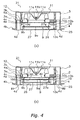
- Figure 4(a) is a cross sectional view of an indoor unit according to the second embodiment during non-operation
- Figure 4(b) is a cross sectional view of the same indoor unit during operation.
- a bottom panel 25 is disposed with an inlet 26 into which air is sucked, and the outlet 4d out of which air is blown.
- a movable panel 27 completely closes the inlet 26 and thus the inlet 26 is not exposed.
- the movable panel 27 and the filter 9 are interconnected by a connecting rod 27a with a predetermined gap therebetween.
- the wire 10b extends vertically upwardly from the hooks 10d attached to the filter 9 and is led to the motor 10a via the plurality of pulleys 10c.
- the motor 10a rotates, the wire 10b is wound up, and the movable panel 27 is pulled up into the casing lower portion 4.
- the filter frame 9b of the filter 9 comes into contact with a mounting surface 4e at a filter mounting position.
- the control unit 13 detects by the position detecting means 14 that the movable panel 27 has risen to a predetermined height, and stops the motor 10a.
- the control unit 13 detects by the position detecting means 14 that the movable panel 27 has reached the inlet 26, and stops the motor 10a.
- the filter 9 is connected to the movable panel 27, and the filter 9 moves to the predetermined mounting position of the filter 9 along with the movement of the movable panel 27.
- the filter 9 and the movable panel 27 are assembled as one unit, the filter 9 can be easily removed and the maintainability of the filter 9 improves.
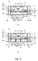
- Figure 5(a) is a cross sectional view of an indoor unit according to the third embodiment during non-operation
- Figure 5(b) is a cross sectional view of the same indoor unit during operation.
- a bottom panel 35 is disposed with an inlet 36 into which air is sucked, and the outlet 4d out of which air is blown.
- a movable panel 37 completely closes the inlet 36 and thus the inlet 36 is not exposed.
- the movable panel 37 is formed by a plurality of plate-shaped small-sized movable panels 37a - 37e.
- guides 39 allow the small-sized movable panels 37a - 37e to move in the vertical direction but not in the horizontal direction.
- a right end of the small-sized movable panel 37b and a left end of the small-sized movable panel 37c are held by the guide 39.
- the small-sized movable panel 37b can move in the vertical direction with respect to the small-sized movable panel 37c by a distance equal to the height of the guide 39.
- a right end of the small-sized movable panel 37c and a left end of the small-sized movable panel 37d are held by the guide 39.
- the small-sized movable panel 37d can move in the vertical direction with respect to the small-sized movable panel 37c by a distance equal to the height of the guide 39.
- a right end of the small-sized movable panel 37d and a left end of the small-sized movable panel 37e are held by the guide 39.
- the small-sized movable panel 37e can move in the vertical direction with respect to the small-sized movable panel 37d by a distance equal to the height of the guide 39.
- the wire 10b extends vertically upwardly from the hooks 10d attached to the small-sized movable panels 37a, 37e, and is led to the motor 10a via the plurality of pulleys 10c.
- the motor 10a rotates, the wire 10b is wound up, and the small-sized movable panels 37a, 37e are pulled up into the casing lower portion 4.
- the small-sized movable panels 37a, 37e rise by a distance equal to the height of the guide 39
- the small-sized movable panels 37b, 37d start rising and rise by a distance equal to the height of the guide 39.
- the control unit 13 detects by the position detecting means 14 that the height to which the small-sized movable panels 37a, 37e have risen becomes equal to the height of the two guides 39, and stops the motor 10a. Consequently, the small-sized movable panels 37a, 37b, 37d, and 37e are arranged in a downward convex pyramid shape with the small-sized movable panel 37c as the center of the shape, and the inlet 36 is opened.
- the motor 10a rotates backwards and the wire 10b is loosened. Then, first, the small-sized movable panels 37b, 37d descend by a distance equal to the height of the guide 39 and reach the inlet 36. Subsequently, the small-sized movable panels 37a, 37e further descend by a distance equal to the height of the guide 39 and reach the inlet 36. At this time, the control unit 13 detects by the position detecting means 14 that the small-sized movable panels 37a, 37e have reached the inlet 36, and stops the motor 10a. In this way, the inlet 36 is closed.
- the movable panel 37 is formed by the plurality of the small-sized movable panels 37a - 37e.
- the plurality of the small-sized movable panels 37a - 37e are horizontally arranged on the inlet 36, and thereby the inlet 36 is closed.
- the driving means 10 first raises the small-sized movable panels 37a, 37e at both ends, and subsequently raises the small-sized movable panels 37d, 37e.
- the small-sized movable panels 37a - 37e are arranged in a downward convex pyramid shape, and the inlet 36 opens.
- the inlet 36 is closed during non-operation and forms a planar portion. Accordingly, the percentage of the planar portion without an opening increases and the flexibility of the design of the bottom panel 35 improves.
- the arrangement pattern of the movable panel 37 changes depending on an open state and a closed state of the inlet 36, the differentiation of the product can be induced by the visual effect in which the design changes. Accordingly, the appeal of the product in the market is promoted.
- the movable panel 37 moves without protruding from the bottom panel 35, the external appearance of the bottom panel 35 does not become impaired.
- Figure 6(a) is a cross sectional view of an indoor unit according to the fourth embodiment during non-operation
- Figure 6(b) is a cross sectional view of the same indoor unit during operation.
- a bottom panel 45 is disposed with an inlet 46 into which air is sucked, and the outlet 4d out of which air is blown.
- the movable panel 47 completely closes the inlet 46 and thus the inlet 46 is not exposed.
- the movable panel 47 is formed by a plurality of plate-shaped small-sized movable panels 47a - 47e. Guides 49 allow the small-sized movable panels 47a - 47e to move in the vertical direction but not in the horizontal direction.
- the wire 10b extends vertically upwardly from the hooks 10d attached to the small-sized movable panel 47c, and is led to the motor 10a via the plurality of pulleys 10c.
- the motor 10a rotates, the wire 10b is wound up, and the small-sized movable panel 47c is pulled up into the casing lower portion 4.
- the small-sized movable panel 47c rises by a distance equal to the height of the guide 49, and subsequently the small-sized movable panels 47b, 47d rise by a distance equal to the height of the guide 49.
- the height to which the small-sized movable panel 47c has risen is equal to the height of the two guides 49.
- the motor 10a further rotates and raises the small-sized movable panels 47a, 47e.
- the control unit 13 detects by the position detecting means 14 that the small-sized movable panel 47c has risen to a predetermined height, and stops the motor 10a. Consequently, the small-sized movable panels 47a, 47b, 47d, and 47e are arranged in an upward convex pyramid shape with the small-sized movable panel 47c as the center, and the inlet 46 is opened.
- the motor 10a rotates backwards and the wire 10b is loosened. Then, first, the small-sized movable panels 47a, 47e descend and reach the inlet 46. Subsequently, the small-sized movable panels 47b, 47d further descend by a distance equal to the height of the guide 49 and reach the inlet 46. The small-sized movable panel 47c further descends by a distance equal to the height of the guide 49 and reaches the inlet 46. At this time, the control unit 13 detects by the position detecting means 14 that the small-sized movable panel 47c has reached the inlet 46, and stops the motor 10a. In this way, the inlet 46 is closed.
- the movable panel 47 is formed by the plurality of small-sized movable panels 47a - 47e.
- the plurality of small-sized movable panels 47a - 47e are horizontally arranged on the inlet 46, and thereby the inlet 46 is closed.
- the driving means 10 first raises the small-sized movable panel 47c at the center of the movable panel 47, subsequently raises the small-sized movable panels 47b, 47d, and lastly raises the small-sized movable panels 47a, 47e.
- the small-sized movable panels 47a - 47e are arranged in an upward convex pyramid shape, and the inlet 46 opens.
- the inlet 46 is closed during non-operation and forms a planar portion. Accordingly, the percentage of the planar portion without an opening increases and the flexibility of the design of the bottom panel 45 improves.
- the arrangement pattern of the movable panel 47 changes depending on an open state and a closed state of the inlet 46, the differentiation of the product can be induced by the visual effect in which the design changes. Accordingly, the appeal of the product in the market is promoted.
- the movable panel 47 moves without protruding from the bottom panel 45, the external appearance of the bottom panel 45 does not become impaired.
- Figure 7(a) is a cross sectional view of an indoor unit according to the fifth embodiment during non-operation
- Figure 7(b) is a cross sectional view of the same indoor unit during operation.
- a bottom panel 55 is disposed with an inlet 56 into which air is sucked, and the outlet 4d out of which air is blown.
- a movable panel 57 completely closes the inlet 56 and thus the inlet 56 is not exposed.
- the movable panel 57 is formed by a first movable panel 58 and a second movable panel 59, and the first movable panel 58 and the second movable panel 59 can rotate in a direction into the casing 2.
- a left end of the first movable panel 58 is rotatably supported at a left end of the inlet 56 by a hinge mechanism.
- a right end of the second movable panel 59 is rotatably supported at a right end of the inlet 56 by a hinge mechanism.
- a right end of the first movable panel 58 and a left end of the second movable panel 59 are disposed side by side on the inlet 56 and close the inlet 56.
- the wire 10b extends vertically upwardly from the hooks 10d attached to the free end side of the first movable panel 58 and the second movable panel 59, and is led to the motor 10a via the plurality of pulleys 10c.
- the motor 10a rotates, the wire 10b is wound up, and the free ends of the first movable panel 58 and the second movable panel 59 are pulled up into the casing lower portion 4. Consequently, the first movable panel 58 rotates counterclockwise about a left end 58a as an axis. Likewise, the second movable panel 59 rotates clockwise about a right end 59a as an axis.
- the control unit 13 detects by the position detecting means 14 that the first movable panel 58 and the second movable panel 59 have rotated approximately 90 degrees, and stops the motor 10a. Consequently, the first movable panel 58 and the second movable panel 59 move in a double door opening manner and the inlet 56 is opened.
- the motor 10a rotates backwards and the wire 10b is loosened. Then, the free ends of the first movable panel 58 and the second movable panel 59 descend in the direction of the inlet 56. Consequently, the first movable panel 58 rotates clockwise about the left end 58a as an axis. Likewise, the second movable panel 59 rotates counterclockwise about the right end 59a as an axis.
- the control unit 13 detects by the position detecting means 14 that the first movable panel 58 and the second movable panel 59 have reached the inlet 56, and stops the motor 10a. In this way, the inlet 56 is closed.
- the movable panel 57 is formed by the first movable panel 58 and the second movable panel 59.
- the first movable panel 58 and the second movable panel 59 are both arranged on the inlet 56 in a freely rotatable manner.
- the first movable panel 58 and the second movable panel 59 are both horizontally arranged on the inlet 56, and thereby the inlet 56 is closed.
- the first movable panel 58 and the second movable panel 59 both rotate toward the inside of the casing lower portion 4, and thereby the inlet 56 is opened.
- the inlet 56 is closed during non-operation and forms a planar portion. Accordingly, the percentage of the planar portion without an opening increases and the flexibility of the design of the bottom panel 55 improves.
- the arrangement pattern of the movable panel 57 changes depending on an open state and a closed state of the inlet 56, the differentiation of the product can be induced by the visual effect in which the design changes. Accordingly, the appeal of the product in the market is promoted.
- the first movable panel 58 and the second movable panel 59 move without protruding from the bottom panel 55, the external appearance of the bottom panel 55 does not become impaired.
- Figure 8(a) is a cross sectional view of an indoor unit according to the sixth embodiment during non-operation
- Figure 8(b) is a cross sectional view of the same indoor unit during operation.
- a bottom panel 65 is disposed with an inlet 66 into which air is sucked, and the outlet 4d out of which air is blown.
- a movable panel 67 completely closes the inlet 66 and thus the inlet 66 is not exposed.
- the movable panel 67 is formed by a first movable panel 68 and a second movable panel 69, and the first movable panel 68 and the second movable panel 69 can rotate in a direction into the casing 2.
- a right end 68a of the first movable panel 68 and a left end 69a of the second movable panel 69 are rotatably supported on the inlet 66 by a hinge mechanism.
- the wire 10b extends upwardly from a left end 68b of the first movable panel 68 and a right end 69b of the second movable panel 69, and is led to the motor 10a via the plurality of pulleys 10c.
- the motor 10a rotates, the wire 10b is wound up, and the left end 68b of the first movable panel 68 and the right end 69b of the second movable panel 69 are pulled up into the casing lower portion 4. Consequently, the first movable panel 68 rotates clockwise about the right end 68a as an axis. Likewise, the second movable panel 69 rotates counterclockwise about the left end 69a as an axis.
- the control unit 13 detects by the position detecting means 14 that the first movable panel 68 and the second movable panel 69 have rotated 90 degrees, and stops the motor 10a. Consequently, the first movable panel 68 and the second movable panel 69 move in a folding movement and the inlet 66 is opened.
- the motor 10a rotates backwards and the wire 10b is loosened.
- the left end 68b of the first movable panel 68 and the right end 69b of the second movable panel 69 descend in the direction of the inlet 66. Consequently, the first movable panel 68 rotates counterclockwise about the right end 68a as an axis.
- the second movable panel 69 rotates clockwise about the left end 69a as an axis.
- the control unit 13 detects by the position detecting means 14 that the left end 68b of the first movable panel 68 and the right end 69b of the second movable panel 69 have reached the inlet 66, and stops the motor 10a. In this way, the inlet 66 is closed.
- the movable panel 67 is formed by the first movable panel 68 and the second movable panel 69.
- the first movable panel 68 and the second movable panel 69 are both arranged on the inlet 66 in a freely rotatable manner.
- the first movable panel 68 and the second movable panel 69 are both horizontally arranged on the inlet 66, and thereby the inlet 66 is closed.
- the first movable panel 68 and the second movable panel 69 both rotate toward the inside of the casing lower portion 4, and thereby the inlet 66 is opened.
- the inlet 66 is closed during non-operation and forms a planar portion. Accordingly, the percentage of the planar portion without an opening increases and the flexibility of the design of the bottom panel 65 improves.
- the arrangement pattern of the movable panel 67 changes depending on an open state and a closed state of the inlet 66, the differentiation of the product can be induced by the visual effect in which the design changes. Accordingly, the appeal of the product in the market is promoted.
- the first movable panel 68 and the second movable panel 69 move without protruding from the bottom panel 65, the external appearance of the bottom panel 65 does not become impaired.
- Figure 9(a) is a cross sectional view of an indoor unit according to the seventh embodiment during non-operation
- Figure 9(b) is a cross sectional view of the same indoor unit during operation.
- a bottom panel 75 is disposed with an inlet 76 into which air is sucked, and an outlet 78 out of which air is blown.
- a first movable panel 77 closes the inlet 76
- a second movable panel 79 closes the outlet 78.
- the inlet 76 and the outlet 78 are not exposed from the bottom panel 75.
- the first movable panel 77 moves in the vertical direction, thereby opening and closing the inlet 76.
- the second movable panel 79 moves in the horizontal direction, thereby opening and closing the outlet 78.
- the driving means 10 includes the motor 10a, the wire 10b, the plurality of pulleys 10c, and the plurality of hooks 10d, and moves the first movable panel 77.
- the driving means 10 includes another motor 10a, a ball screw 10e, and slide screws 10f, 10g, and moves the second movable panel 79.
- the first movable panel 77 closes the inlet 76
- the second movable panel 79 closes the outlet 78. Therefore, only the peripheral boundaries of the first movable panel 77 and the second movable panel 79 are visible on the bottom panel 75.
- the motor 10a rotates, the wire 10b is wound up, and the first movable panel 77 is pulled up into the casing lower portion 4.
- the other motor 10a rotates the ball screw 10e and moves the slide screw 10f and the slide screw 10g in a sliding manner toward the center of the bottom panel 75.
- the slide screw 10f is connected to the second movable panel 79 on the left, and the second movable panel 79 on the left moves to the right as the ball screw 10e rotates.
- the slide screw 10g is connected to the second movable panel 79 on the right, and the second movable panel 79 on the right moves to the left as the ball screw 10e rotates.
- the control unit 13 detects by the position detecting means 14 that the first movable panel 77 has risen to a predetermined height, and stops the motor 10a.
- control unit 13 detects by the position detecting means 14 that the second movable panel 79 has moved to a predetermined position, and stops the other motor 10a.
- control unit 13 detects by the position detecting means 14 that the first movable panel 77 has reached the inlet 76, and stops the motor 10a. Further, the control unit 13 detects by the position detecting means 14 that the second movable panel 79 has reached the original position, and stops the other motor 10a.
- the indoor unit 71 is equipped with the casing 2 embedded in a ceiling and the bottom panel 75 exposed from a ceiling surface.
- the bottom panel 75 is disposed with the inlet 76 into which air is sucked, and the outlet 78 out of which air is blown.
- the driving means 10 moves the first movable panel 77 in the vertical direction without causing the first movable panel 77 to protrude from the bottom panel 75, thereby opening and closing the inlet 76. Further, the driving means 10 moves the second movable panel 79 in the horizontal direction without causing the second movable panel 79 to protrude from the bottom panel 75, thereby opening and closing the outlet 78.
- the filter 9 is housed in the casing 2, and is arranged away from the bottom panel 75.
- the inlet 76 and the outlet 78 are closed during non-operation and forms a planar portion. Accordingly, the percentage of the planar portion without an opening increases and the flexibility of the design of the bottom panel 75 improves. In addition, since the first movable panel 77 and the second movable panel 79 move without protruding from the bottom panel 75, the external appearance of the bottom panel 75 does not become impaired. In addition, the shape of the bottom panel 75 is hardly limited by the filter 9 and the flexibility of the design of the bottom panel 75 improves. Further, since the filter 9 is located at a position that is not noticeable by people, contamination on the filter 9 does not impair the external appearance of the bottom panel 75.
- the driving means 10 is constituted by the motor 10a, the wire 10b, and the pulleys 10c, however, the driving means 10 may be constituted by a motor and a gear.
- the indoor unit of the present invention is useful as an indoor unit of a ceiling-embedded type or ceiling-suspended type air conditioner in which the flexibility of the design of a bottom panel thereof is desired to be improved.
Landscapes
- Engineering & Computer Science (AREA)
- Chemical & Material Sciences (AREA)
- Combustion & Propulsion (AREA)
- Mechanical Engineering (AREA)
- General Engineering & Computer Science (AREA)
- Physics & Mathematics (AREA)
- Thermal Sciences (AREA)
- Air Filters, Heat-Exchange Apparatuses, And Housings Of Air-Conditioning Units (AREA)
- Power-Operated Mechanisms For Wings (AREA)
- Ventilation (AREA)
Claims (8)
- Unité intérieure (1, 21, 31, 41, 51, 61, 71) d'un climatiseur de type encastré dans le plafond ou de type suspendu au plafond, comprenant :un panneau inférieur (5, 25, 35, 45, 55, 65, 75) constituant une surface inférieure ;une entrée (6, 26, 36, 46, 56, 66, 76) disposée sur le panneau inférieur (5, 25, 35, 45, 55, 65, 75) ;un panneau mobile (7, 27, 37, 47, 57, 67, 77) configuré pour fermer l'entrée (6, 26, 36, 46, 56, 66, 76) pendant un arrêt de fonctionnement ; etun moyen d'entraînement (10) configuré pour déplacer ou faire tourner le panneau mobile (7, 27, 37, 47, 57, 67, 77),caractérisée en ce quependant le fonctionnement, le panneau mobile (7, 27, 37, 47, 57, 67, 77) est adapté pour se déplacer ou tourner moyennant quoi il s'éloigne au-dessus d'une surface inférieure du panneau inférieur (5, 25, 35, 45, 55, 65, 75).
- Unité intérieure (21) d'un climatiseur selon la revendication 1, comprenant en outre
un ventilateur (11) configuré pour aspirer l'air à partir de l'entrée (26) ; et
un filtre (9) configuré pour éliminer la poussière dans l'air aspiré à partir de l'entrée (26),
dans laquelle
le filtre (9) est relié au panneau mobile (27), et se déplace vers une position de montage prédéterminée du filtre (9) le long du déplacement du panneau mobile (27). - Unité intérieure (31, 41) d'un climatiseur selon la revendication 1, dans laquelle
le panneau mobile (37, 47) est formé par une pluralité de panneaux mobiles de petite taille (37a à 37e, 47a à 47e), et
pendant le fonctionnement, la pluralité de panneaux mobiles de petite taille (37a à 37e, 47a à 47e) se déplacent et sont agencés sous une forme pyramidale au-dessus d'une surface inférieure du panneau inférieur (35, 45). - Unité intérieure (51, 61) d'un climatiseur selon la revendication 1, dans laquelle
le panneau mobile (57, 67) est formé par au moins un premier panneau mobile (58, 68) et un deuxième panneau mobile (59, 69), et
pendant le fonctionnement, le premier panneau mobile (58, 68) et le deuxième panneau mobile (59, 69) tournent et s'ouvrent vers le haut au-dessus d'une surface inférieure du panneau inférieur (55, 65). - Unité intérieure (71) d'un climatiseur selon la revendication 1 comprenant en outre :une sortie (78) disposée sur le panneau inférieur (75) ; etun deuxième panneau mobile (79) configuré pour fermer la sortie (78) pendant un arrêt de fonctionnement,dans laquelle,pendant le fonctionnement, le premier panneau mobile (77) se déplace ou tourne et s'éloigne au-dessus d'une surface inférieure du panneau inférieur (75), etpendant le fonctionnement, le deuxième panneau mobile (79) se déplace ou tourne à distance de la sortie (78).
- Unité intérieure (71) d'un climatiseur selon la revendication 5, dans laquelle
pendant le fonctionnement, le deuxième panneau mobile (79) se déplace de manière parallèle vers le centre du panneau inférieur (75). - Unité intérieure (1, 21, 31, 41, 51, 61, 71) d'un climatiseur selon la revendication 1, dans laquelle
le moyen d'entraînement (10) utilise un moteur (10a) en tant que source d'entraînement. - Unité intérieure (1, 21, 31, 41, 51, 61, 71) d'un climatiseur selon la revendication 1, dans laquelle
le panneau inférieur (5, 25, 35, 45, 55, 65, 75) et le moyen d'entraînement (10) sont prévus en tant que série d'assemblage.
Applications Claiming Priority (2)
| Application Number | Priority Date | Filing Date | Title |
|---|---|---|---|
| JP2006114821A JP3998032B1 (ja) | 2006-04-18 | 2006-04-18 | 空気調和装置の室内機 |
| PCT/JP2007/058271 WO2007123082A1 (fr) | 2006-04-18 | 2007-04-16 | Unité d'intérieur pour climatiseur |
Publications (3)
| Publication Number | Publication Date |
|---|---|
| EP2009363A1 EP2009363A1 (fr) | 2008-12-31 |
| EP2009363A4 EP2009363A4 (fr) | 2013-11-27 |
| EP2009363B1 true EP2009363B1 (fr) | 2015-08-26 |
Family
ID=38624982
Family Applications (1)
| Application Number | Title | Priority Date | Filing Date |
|---|---|---|---|
| EP07741707.9A Active EP2009363B1 (fr) | 2006-04-18 | 2007-04-16 | Unité d'intérieur pour climatiseur |
Country Status (7)
| Country | Link |
|---|---|
| US (1) | US20090100851A1 (fr) |
| EP (1) | EP2009363B1 (fr) |
| JP (1) | JP3998032B1 (fr) |
| KR (1) | KR100949293B1 (fr) |
| CN (1) | CN101331363B (fr) |
| AU (1) | AU2007241895B8 (fr) |
| WO (1) | WO2007123082A1 (fr) |
Families Citing this family (19)
| Publication number | Priority date | Publication date | Assignee | Title |
|---|---|---|---|---|
| JP4001172B1 (ja) * | 2006-04-17 | 2007-10-31 | ダイキン工業株式会社 | 空気調和装置 |
| CN101796349B (zh) * | 2007-09-07 | 2012-12-12 | 东芝开利株式会社 | 嵌入天花板的空调 |
| JP5194023B2 (ja) * | 2007-10-25 | 2013-05-08 | 東芝キヤリア株式会社 | 天井埋込型の空気調和機 |
| JP5055194B2 (ja) * | 2008-04-24 | 2012-10-24 | 三菱重工業株式会社 | 室内機ユニットおよび空気調和機 |
| JP2009293807A (ja) * | 2008-06-02 | 2009-12-17 | Daikin Ind Ltd | 空調室内機の可動パネル |
| JP5283448B2 (ja) * | 2008-08-12 | 2013-09-04 | 三洋電機株式会社 | 空気調和機 |
| JP2010043781A (ja) * | 2008-08-12 | 2010-02-25 | Sanyo Electric Co Ltd | 空気調和機 |
| KR101598626B1 (ko) * | 2009-01-09 | 2016-02-29 | 엘지전자 주식회사 | 공기 조화기 실내기 |
| KR101558576B1 (ko) * | 2009-01-09 | 2015-10-19 | 엘지전자 주식회사 | 공기 조화기의 실내기 |
| JP2011012936A (ja) * | 2009-07-06 | 2011-01-20 | Hitachi Appliances Inc | 天井埋込型空気調和機 |
| JP2013194930A (ja) * | 2012-03-16 | 2013-09-30 | Fujitsu General Ltd | 天井埋込形空気調和機 |
| CN103807989B (zh) * | 2014-03-05 | 2016-08-24 | 珠海格力电器股份有限公司 | 风管机出风口装置及具有其的空调器 |
| US20170343235A1 (en) * | 2015-06-12 | 2017-11-30 | Mitsubishi Electric Corporation | Ceiling cassette air conditioner |
| CN105546661B (zh) * | 2016-02-19 | 2018-11-06 | 珠海格力电器股份有限公司 | 空调器 |
| CN106066061B (zh) * | 2016-07-18 | 2021-12-03 | 珠海格力电器股份有限公司 | 风口装置及风管机 |
| JP6914794B2 (ja) * | 2017-09-27 | 2021-08-04 | 東芝キヤリア株式会社 | 空気調和機 |
| KR102235273B1 (ko) * | 2017-12-21 | 2021-04-02 | 엘지전자 주식회사 | 공기조화기의 천장형 실내기 |
| EP3828475A4 (fr) * | 2018-07-26 | 2021-11-17 | Mitsubishi Electric Corporation | Unité intérieure et appareil à cycle de réfrigération |
| CN112728639A (zh) * | 2021-01-27 | 2021-04-30 | 青岛海尔空调电子有限公司 | 用于空调器的出风口结构和空调器 |
Family Cites Families (8)
| Publication number | Priority date | Publication date | Assignee | Title |
|---|---|---|---|---|
| JP3552851B2 (ja) * | 1996-08-08 | 2004-08-11 | 小波株式会社 | 天井埋込型空気調和機 |
| JP3816170B2 (ja) * | 1996-12-27 | 2006-08-30 | 小波株式会社 | 天井埋込型空気調和装置 |
| JP3812027B2 (ja) | 1997-01-22 | 2006-08-23 | 松下電器産業株式会社 | 空気調和機 |
| KR100441024B1 (ko) * | 2002-08-19 | 2004-07-21 | 삼성전자주식회사 | 공기조화기 |
| EP1617151B1 (fr) * | 2003-03-26 | 2017-09-20 | Daikin Industries, Ltd. | Unite d'interieur pour climatiseur |
| US7170745B2 (en) * | 2003-04-30 | 2007-01-30 | Hewlett-Packard Development Company, L.P. | Electronics rack having an angled panel |
| KR20050078877A (ko) * | 2004-02-03 | 2005-08-08 | 엘지전자 주식회사 | 천장형 공기조화기의 실내기 |
| JP4544944B2 (ja) * | 2004-08-31 | 2010-09-15 | 三洋電機株式会社 | 天井埋込型式空気調和装置 |
-
2006
- 2006-04-18 JP JP2006114821A patent/JP3998032B1/ja not_active Expired - Lifetime
-
2007
- 2007-04-16 CN CN2007800006769A patent/CN101331363B/zh active Active
- 2007-04-16 US US12/063,641 patent/US20090100851A1/en not_active Abandoned
- 2007-04-16 EP EP07741707.9A patent/EP2009363B1/fr active Active
- 2007-04-16 KR KR1020077030066A patent/KR100949293B1/ko not_active Expired - Fee Related
- 2007-04-16 WO PCT/JP2007/058271 patent/WO2007123082A1/fr not_active Ceased
- 2007-04-16 AU AU2007241895A patent/AU2007241895B8/en not_active Ceased
Also Published As
| Publication number | Publication date |
|---|---|
| CN101331363B (zh) | 2011-02-09 |
| AU2007241895B8 (en) | 2010-02-25 |
| EP2009363A1 (fr) | 2008-12-31 |
| JP3998032B1 (ja) | 2007-10-24 |
| CN101331363A (zh) | 2008-12-24 |
| AU2007241895B2 (en) | 2009-11-19 |
| AU2007241895A1 (en) | 2007-11-01 |
| KR20080016670A (ko) | 2008-02-21 |
| US20090100851A1 (en) | 2009-04-23 |
| JP2007285629A (ja) | 2007-11-01 |
| WO2007123082A1 (fr) | 2007-11-01 |
| EP2009363A4 (fr) | 2013-11-27 |
| KR100949293B1 (ko) | 2010-03-24 |
Similar Documents
| Publication | Publication Date | Title |
|---|---|---|
| EP2009363B1 (fr) | Unité d'intérieur pour climatiseur | |
| EP2226576A2 (fr) | Partie intérieure d'un climatiseur | |
| KR101321544B1 (ko) | 천장형 공기조화기 | |
| KR20090043232A (ko) | 공기조화기 | |
| KR20100051956A (ko) | 공기 조화기의 실내기 | |
| JP2019011928A (ja) | 天井埋込型空気調和機 | |
| CN203940528U (zh) | 空调机的室内机 | |
| KR101517969B1 (ko) | 공기조화기 | |
| EP2251617B1 (fr) | Matériel climatiseur d'intérieur | |
| KR101450565B1 (ko) | 공기조화기 | |
| JP2013120033A (ja) | 空気調和機の室内機 | |
| CN203231494U (zh) | 安装面板以及侧出风、下出风及上出风式空调机室内机 | |
| JP2010243028A (ja) | サーキュレータ | |
| JP6069866B2 (ja) | 空調室内機 | |
| JP4442298B2 (ja) | 空気調和機の室外ユニット | |
| KR101582240B1 (ko) | 공기조화기 및 그 운전 방법 | |
| KR101203569B1 (ko) | 공기조화기의 실내기 | |
| JP3145410U (ja) | 天井の軽量鋼構造体に取り付けるためのファン構造体 | |
| JP2003176929A (ja) | 天井設置型空気調和機 | |
| CN100541018C (zh) | 分体式空调器的室内机 | |
| CN101737919A (zh) | 空调机 | |
| KR101482128B1 (ko) | 공기조화기 | |
| JP2016090156A (ja) | 空気調和装置 | |
| JP2010048469A (ja) | 空気調和機 | |
| KR20040045516A (ko) | 창문형 공기조화기의 모터 설치구조 |
Legal Events
| Date | Code | Title | Description |
|---|---|---|---|
| PUAI | Public reference made under article 153(3) epc to a published international application that has entered the european phase |
Free format text: ORIGINAL CODE: 0009012 |
|
| 17P | Request for examination filed |
Effective date: 20080215 |
|
| AK | Designated contracting states |
Kind code of ref document: A1 Designated state(s): AT BE BG CH CY CZ DE DK EE ES FI FR GB GR HU IE IS IT LI LT LU LV MC MT NL PL PT RO SE SI SK TR |
|
| AX | Request for extension of the european patent |
Extension state: AL BA HR MK RS |
|
| DAX | Request for extension of the european patent (deleted) | ||
| A4 | Supplementary search report drawn up and despatched |
Effective date: 20131030 |
|
| RIC1 | Information provided on ipc code assigned before grant |
Ipc: F24F 13/16 20060101ALI20131024BHEP Ipc: F24F 1/00 20110101ALI20131024BHEP Ipc: F24F 13/06 20060101ALI20131024BHEP Ipc: F24F 11/00 20060101ALI20131024BHEP Ipc: F24F 13/20 20060101AFI20131024BHEP Ipc: F24F 13/28 20060101ALI20131024BHEP |
|
| GRAP | Despatch of communication of intention to grant a patent |
Free format text: ORIGINAL CODE: EPIDOSNIGR1 |
|
| INTG | Intention to grant announced |
Effective date: 20150410 |
|
| GRAS | Grant fee paid |
Free format text: ORIGINAL CODE: EPIDOSNIGR3 |
|
| GRAA | (expected) grant |
Free format text: ORIGINAL CODE: 0009210 |
|
| AK | Designated contracting states |
Kind code of ref document: B1 Designated state(s): AT BE BG CH CY CZ DE DK EE ES FI FR GB GR HU IE IS IT LI LT LU LV MC MT NL PL PT RO SE SI SK TR |
|
| REG | Reference to a national code |
Ref country code: GB Ref legal event code: FG4D |
|
| REG | Reference to a national code |
Ref country code: CH Ref legal event code: EP |
|
| REG | Reference to a national code |
Ref country code: AT Ref legal event code: REF Ref document number: 745422 Country of ref document: AT Kind code of ref document: T Effective date: 20150915 |
|
| REG | Reference to a national code |
Ref country code: IE Ref legal event code: FG4D |
|
| REG | Reference to a national code |
Ref country code: DE Ref legal event code: R096 Ref document number: 602007042785 Country of ref document: DE |
|
| REG | Reference to a national code |
Ref country code: AT Ref legal event code: MK05 Ref document number: 745422 Country of ref document: AT Kind code of ref document: T Effective date: 20150826 |
|
| REG | Reference to a national code |
Ref country code: LT Ref legal event code: MG4D |
|
| PG25 | Lapsed in a contracting state [announced via postgrant information from national office to epo] |
Ref country code: LV Free format text: LAPSE BECAUSE OF FAILURE TO SUBMIT A TRANSLATION OF THE DESCRIPTION OR TO PAY THE FEE WITHIN THE PRESCRIBED TIME-LIMIT Effective date: 20150826 Ref country code: LT Free format text: LAPSE BECAUSE OF FAILURE TO SUBMIT A TRANSLATION OF THE DESCRIPTION OR TO PAY THE FEE WITHIN THE PRESCRIBED TIME-LIMIT Effective date: 20150826 Ref country code: FI Free format text: LAPSE BECAUSE OF FAILURE TO SUBMIT A TRANSLATION OF THE DESCRIPTION OR TO PAY THE FEE WITHIN THE PRESCRIBED TIME-LIMIT Effective date: 20150826 Ref country code: GR Free format text: LAPSE BECAUSE OF FAILURE TO SUBMIT A TRANSLATION OF THE DESCRIPTION OR TO PAY THE FEE WITHIN THE PRESCRIBED TIME-LIMIT Effective date: 20151127 |
|
| REG | Reference to a national code |
Ref country code: NL Ref legal event code: MP Effective date: 20150826 |
|
| PG25 | Lapsed in a contracting state [announced via postgrant information from national office to epo] |
Ref country code: ES Free format text: LAPSE BECAUSE OF FAILURE TO SUBMIT A TRANSLATION OF THE DESCRIPTION OR TO PAY THE FEE WITHIN THE PRESCRIBED TIME-LIMIT Effective date: 20150826 Ref country code: IS Free format text: LAPSE BECAUSE OF FAILURE TO SUBMIT A TRANSLATION OF THE DESCRIPTION OR TO PAY THE FEE WITHIN THE PRESCRIBED TIME-LIMIT Effective date: 20151226 Ref country code: PL Free format text: LAPSE BECAUSE OF FAILURE TO SUBMIT A TRANSLATION OF THE DESCRIPTION OR TO PAY THE FEE WITHIN THE PRESCRIBED TIME-LIMIT Effective date: 20150826 Ref country code: PT Free format text: LAPSE BECAUSE OF FAILURE TO SUBMIT A TRANSLATION OF THE DESCRIPTION OR TO PAY THE FEE WITHIN THE PRESCRIBED TIME-LIMIT Effective date: 20151228 Ref country code: AT Free format text: LAPSE BECAUSE OF FAILURE TO SUBMIT A TRANSLATION OF THE DESCRIPTION OR TO PAY THE FEE WITHIN THE PRESCRIBED TIME-LIMIT Effective date: 20150826 Ref country code: SE Free format text: LAPSE BECAUSE OF FAILURE TO SUBMIT A TRANSLATION OF THE DESCRIPTION OR TO PAY THE FEE WITHIN THE PRESCRIBED TIME-LIMIT Effective date: 20150826 |
|
| PG25 | Lapsed in a contracting state [announced via postgrant information from national office to epo] |
Ref country code: NL Free format text: LAPSE BECAUSE OF FAILURE TO SUBMIT A TRANSLATION OF THE DESCRIPTION OR TO PAY THE FEE WITHIN THE PRESCRIBED TIME-LIMIT Effective date: 20150826 |
|
| REG | Reference to a national code |
Ref country code: FR Ref legal event code: PLFP Year of fee payment: 10 |
|
| PG25 | Lapsed in a contracting state [announced via postgrant information from national office to epo] |
Ref country code: CZ Free format text: LAPSE BECAUSE OF FAILURE TO SUBMIT A TRANSLATION OF THE DESCRIPTION OR TO PAY THE FEE WITHIN THE PRESCRIBED TIME-LIMIT Effective date: 20150826 Ref country code: EE Free format text: LAPSE BECAUSE OF FAILURE TO SUBMIT A TRANSLATION OF THE DESCRIPTION OR TO PAY THE FEE WITHIN THE PRESCRIBED TIME-LIMIT Effective date: 20150826 Ref country code: SK Free format text: LAPSE BECAUSE OF FAILURE TO SUBMIT A TRANSLATION OF THE DESCRIPTION OR TO PAY THE FEE WITHIN THE PRESCRIBED TIME-LIMIT Effective date: 20150826 Ref country code: DK Free format text: LAPSE BECAUSE OF FAILURE TO SUBMIT A TRANSLATION OF THE DESCRIPTION OR TO PAY THE FEE WITHIN THE PRESCRIBED TIME-LIMIT Effective date: 20150826 |
|
| REG | Reference to a national code |
Ref country code: DE Ref legal event code: R097 Ref document number: 602007042785 Country of ref document: DE |
|
| PG25 | Lapsed in a contracting state [announced via postgrant information from national office to epo] |
Ref country code: RO Free format text: LAPSE BECAUSE OF FAILURE TO SUBMIT A TRANSLATION OF THE DESCRIPTION OR TO PAY THE FEE WITHIN THE PRESCRIBED TIME-LIMIT Effective date: 20150826 |
|
| PLBE | No opposition filed within time limit |
Free format text: ORIGINAL CODE: 0009261 |
|
| STAA | Information on the status of an ep patent application or granted ep patent |
Free format text: STATUS: NO OPPOSITION FILED WITHIN TIME LIMIT |
|
| 26N | No opposition filed |
Effective date: 20160530 |
|
| PG25 | Lapsed in a contracting state [announced via postgrant information from national office to epo] |
Ref country code: BE Free format text: LAPSE BECAUSE OF NON-PAYMENT OF DUE FEES Effective date: 20160430 Ref country code: SI Free format text: LAPSE BECAUSE OF FAILURE TO SUBMIT A TRANSLATION OF THE DESCRIPTION OR TO PAY THE FEE WITHIN THE PRESCRIBED TIME-LIMIT Effective date: 20150826 |
|
| REG | Reference to a national code |
Ref country code: CH Ref legal event code: PL |
|
| GBPC | Gb: european patent ceased through non-payment of renewal fee |
Effective date: 20160416 |
|
| PG25 | Lapsed in a contracting state [announced via postgrant information from national office to epo] |
Ref country code: BE Free format text: LAPSE BECAUSE OF FAILURE TO SUBMIT A TRANSLATION OF THE DESCRIPTION OR TO PAY THE FEE WITHIN THE PRESCRIBED TIME-LIMIT Effective date: 20150826 Ref country code: LU Free format text: LAPSE BECAUSE OF FAILURE TO SUBMIT A TRANSLATION OF THE DESCRIPTION OR TO PAY THE FEE WITHIN THE PRESCRIBED TIME-LIMIT Effective date: 20160416 |
|
| REG | Reference to a national code |
Ref country code: IE Ref legal event code: MM4A |
|
| PG25 | Lapsed in a contracting state [announced via postgrant information from national office to epo] |
Ref country code: LI Free format text: LAPSE BECAUSE OF NON-PAYMENT OF DUE FEES Effective date: 20160430 Ref country code: GB Free format text: LAPSE BECAUSE OF NON-PAYMENT OF DUE FEES Effective date: 20160416 Ref country code: CH Free format text: LAPSE BECAUSE OF NON-PAYMENT OF DUE FEES Effective date: 20160430 |
|
| REG | Reference to a national code |
Ref country code: FR Ref legal event code: PLFP Year of fee payment: 11 |
|
| PG25 | Lapsed in a contracting state [announced via postgrant information from national office to epo] |
Ref country code: IE Free format text: LAPSE BECAUSE OF NON-PAYMENT OF DUE FEES Effective date: 20160416 |
|
| REG | Reference to a national code |
Ref country code: FR Ref legal event code: PLFP Year of fee payment: 12 |
|
| PG25 | Lapsed in a contracting state [announced via postgrant information from national office to epo] |
Ref country code: HU Free format text: LAPSE BECAUSE OF FAILURE TO SUBMIT A TRANSLATION OF THE DESCRIPTION OR TO PAY THE FEE WITHIN THE PRESCRIBED TIME-LIMIT; INVALID AB INITIO Effective date: 20070416 Ref country code: CY Free format text: LAPSE BECAUSE OF FAILURE TO SUBMIT A TRANSLATION OF THE DESCRIPTION OR TO PAY THE FEE WITHIN THE PRESCRIBED TIME-LIMIT Effective date: 20150826 |
|
| PG25 | Lapsed in a contracting state [announced via postgrant information from national office to epo] |
Ref country code: MC Free format text: LAPSE BECAUSE OF FAILURE TO SUBMIT A TRANSLATION OF THE DESCRIPTION OR TO PAY THE FEE WITHIN THE PRESCRIBED TIME-LIMIT Effective date: 20150826 Ref country code: MT Free format text: LAPSE BECAUSE OF NON-PAYMENT OF DUE FEES Effective date: 20160430 Ref country code: TR Free format text: LAPSE BECAUSE OF FAILURE TO SUBMIT A TRANSLATION OF THE DESCRIPTION OR TO PAY THE FEE WITHIN THE PRESCRIBED TIME-LIMIT Effective date: 20150826 |
|
| PG25 | Lapsed in a contracting state [announced via postgrant information from national office to epo] |
Ref country code: BG Free format text: LAPSE BECAUSE OF FAILURE TO SUBMIT A TRANSLATION OF THE DESCRIPTION OR TO PAY THE FEE WITHIN THE PRESCRIBED TIME-LIMIT Effective date: 20150826 |
|
| P01 | Opt-out of the competence of the unified patent court (upc) registered |
Effective date: 20230525 |
|
| PGFP | Annual fee paid to national office [announced via postgrant information from national office to epo] |
Ref country code: FR Payment date: 20250310 Year of fee payment: 19 |
|
| PGFP | Annual fee paid to national office [announced via postgrant information from national office to epo] |
Ref country code: IT Payment date: 20250320 Year of fee payment: 19 |
|
| PGFP | Annual fee paid to national office [announced via postgrant information from national office to epo] |
Ref country code: DE Payment date: 20250305 Year of fee payment: 19 |