EP2009376A1 - Module d'évaporateur ainsi qu'appareil de réfrigération et/ou de congélation doté d'un tel module d'évaporateur - Google Patents
Module d'évaporateur ainsi qu'appareil de réfrigération et/ou de congélation doté d'un tel module d'évaporateur Download PDFInfo
- Publication number
- EP2009376A1 EP2009376A1 EP08011598A EP08011598A EP2009376A1 EP 2009376 A1 EP2009376 A1 EP 2009376A1 EP 08011598 A EP08011598 A EP 08011598A EP 08011598 A EP08011598 A EP 08011598A EP 2009376 A1 EP2009376 A1 EP 2009376A1
- Authority
- EP
- European Patent Office
- Prior art keywords
- evaporator module
- housing
- fan
- module according
- fan housing
- Prior art date
- Legal status (The legal status is an assumption and is not a legal conclusion. Google has not performed a legal analysis and makes no representation as to the accuracy of the status listed.)
- Withdrawn
Links
- 238000001816 cooling Methods 0.000 title 1
- 238000007710 freezing Methods 0.000 title 1
- 230000008014 freezing Effects 0.000 title 1
- 238000009434 installation Methods 0.000 claims description 7
- 230000008878 coupling Effects 0.000 claims description 5
- 238000010168 coupling process Methods 0.000 claims description 5
- 238000005859 coupling reaction Methods 0.000 claims description 5
- 229920002725 thermoplastic elastomer Polymers 0.000 claims description 4
- 238000007789 sealing Methods 0.000 claims description 2
- 238000000034 method Methods 0.000 claims 1
- 229920006328 Styrofoam Polymers 0.000 description 2
- 239000008261 styrofoam Substances 0.000 description 2
- 239000004793 Polystyrene Substances 0.000 description 1
- 230000000712 assembly Effects 0.000 description 1
- 238000000429 assembly Methods 0.000 description 1
- 238000004891 communication Methods 0.000 description 1
- 238000005516 engineering process Methods 0.000 description 1
- 239000000284 extract Substances 0.000 description 1
- 238000009413 insulation Methods 0.000 description 1
- 238000004519 manufacturing process Methods 0.000 description 1
- 229920002223 polystyrene Polymers 0.000 description 1
- 238000005476 soldering Methods 0.000 description 1
Images


Classifications
-
- F—MECHANICAL ENGINEERING; LIGHTING; HEATING; WEAPONS; BLASTING
- F25—REFRIGERATION OR COOLING; COMBINED HEATING AND REFRIGERATION SYSTEMS; HEAT PUMP SYSTEMS; MANUFACTURE OR STORAGE OF ICE; LIQUEFACTION SOLIDIFICATION OF GASES
- F25D—REFRIGERATORS; COLD ROOMS; ICE-BOXES; COOLING OR FREEZING APPARATUS NOT OTHERWISE PROVIDED FOR
- F25D17/00—Arrangements for circulating cooling fluids; Arrangements for circulating gas, e.g. air, within refrigerated spaces
- F25D17/04—Arrangements for circulating cooling fluids; Arrangements for circulating gas, e.g. air, within refrigerated spaces for circulating air, e.g. by convection
- F25D17/06—Arrangements for circulating cooling fluids; Arrangements for circulating gas, e.g. air, within refrigerated spaces for circulating air, e.g. by convection by forced circulation
- F25D17/067—Evaporator fan units
-
- F—MECHANICAL ENGINEERING; LIGHTING; HEATING; WEAPONS; BLASTING
- F25—REFRIGERATION OR COOLING; COMBINED HEATING AND REFRIGERATION SYSTEMS; HEAT PUMP SYSTEMS; MANUFACTURE OR STORAGE OF ICE; LIQUEFACTION SOLIDIFICATION OF GASES
- F25B—REFRIGERATION MACHINES, PLANTS OR SYSTEMS; COMBINED HEATING AND REFRIGERATION SYSTEMS; HEAT PUMP SYSTEMS
- F25B2500/00—Problems to be solved
- F25B2500/13—Vibrations
-
- F—MECHANICAL ENGINEERING; LIGHTING; HEATING; WEAPONS; BLASTING
- F25—REFRIGERATION OR COOLING; COMBINED HEATING AND REFRIGERATION SYSTEMS; HEAT PUMP SYSTEMS; MANUFACTURE OR STORAGE OF ICE; LIQUEFACTION SOLIDIFICATION OF GASES
- F25D—REFRIGERATORS; COLD ROOMS; ICE-BOXES; COOLING OR FREEZING APPARATUS NOT OTHERWISE PROVIDED FOR
- F25D23/00—General constructional features
- F25D23/006—General constructional features for mounting refrigerating machinery components
-
- F—MECHANICAL ENGINEERING; LIGHTING; HEATING; WEAPONS; BLASTING
- F25—REFRIGERATION OR COOLING; COMBINED HEATING AND REFRIGERATION SYSTEMS; HEAT PUMP SYSTEMS; MANUFACTURE OR STORAGE OF ICE; LIQUEFACTION SOLIDIFICATION OF GASES
- F25D—REFRIGERATORS; COLD ROOMS; ICE-BOXES; COOLING OR FREEZING APPARATUS NOT OTHERWISE PROVIDED FOR
- F25D2317/00—Details or arrangements for circulating cooling fluids; Details or arrangements for circulating gas, e.g. air, within refrigerated spaces, not provided for in other groups of this subclass
- F25D2317/06—Details or arrangements for circulating cooling fluids; Details or arrangements for circulating gas, e.g. air, within refrigerated spaces, not provided for in other groups of this subclass with forced air circulation
- F25D2317/068—Details or arrangements for circulating cooling fluids; Details or arrangements for circulating gas, e.g. air, within refrigerated spaces, not provided for in other groups of this subclass with forced air circulation characterised by the fans
- F25D2317/0681—Details thereof
-
- F—MECHANICAL ENGINEERING; LIGHTING; HEATING; WEAPONS; BLASTING
- F25—REFRIGERATION OR COOLING; COMBINED HEATING AND REFRIGERATION SYSTEMS; HEAT PUMP SYSTEMS; MANUFACTURE OR STORAGE OF ICE; LIQUEFACTION SOLIDIFICATION OF GASES
- F25D—REFRIGERATORS; COLD ROOMS; ICE-BOXES; COOLING OR FREEZING APPARATUS NOT OTHERWISE PROVIDED FOR
- F25D2400/00—General features of, or devices for refrigerators, cold rooms, ice-boxes, or for cooling or freezing apparatus not covered by any other subclass
- F25D2400/40—Refrigerating devices characterised by electrical wiring
Definitions
- the present invention relates to an evaporator module with an evaporator module housing and with a fan.
- no-frost evaporator modules for freezers which are usually arranged below the ceiling on the inner container of the device.
- the evaporator modules usually have a fan, which extracts the cold air from the evaporator module housing and leads into the space to be cooled.
- the present invention is therefore the object of developing an evaporator module of the type mentioned in such a way that the running noise of the fan is low and that the evaporator module is also designed to be service-friendly.
- an evaporator module having the features of claim 1.
- the fan is arranged in a fan housing, wherein the entire fan housing is designed as a respect to the evaporator module housing rashs component, wherein between the fan housing and the evaporator module housing for the purpose of noise decoupling one or more vibration dampers are arranged.
- the entire fan housing including all air-conducting elements, such as recesses, air guide elements and the like is designed as an independent component that can be removed if necessary from the evaporator module housing, so that in the case of service not the entire evaporator module, but optionally only the fan housing or its fan must be replaced.
- the evaporator module housing has at least one wall, in which a recess is provided, in which the fan housing is accommodated.
- This recess can be made open at the top, so that the fan housing is inserted, for example, from above into the recess.
- the recess may extend over the entire height of the wall or over a substantial part of the wall.
- the one or more vibration dampers consist of thermoplastic elastomer or have such. It is also conceivable that the vibration damper is molded in 2-component technology. In a further embodiment of the invention it is provided that the recess is bounded by plate-shaped projections of the evaporator module housing and that the vibration damper extending between the fan housing and these projections.
- the fan housing may have larger dimensions than the recess, so that the fan housing with the recess defining parts of the evaporator module housing overlaps partially. In these overlapping areas, the vibration dampers may be arranged.
- the fan housing may have on its side facing away from the interior of the evaporator module housing side a seal for sealing the fan housing relative to the inner container of a refrigerator and / or freezer.
- the fan housing has an edge region on which the seal is plugged.
- the seal is designed in mirror image in cross-section, so that it is not important to pay attention to their orientation during assembly.
- the seal is mounted on the fan housing via a latching connection.
- a latching hook geometry allows the reliable fixation of the seal on the housing with little effort.
- a removable from the fan housing holding part is provided, on which the fan is arranged.
- This holding part can be designed with multiple arms, wherein the arms can be fixed to the fan housing via positive connections. It is conceivable, for example, to provide a three-arm arrangement.
- one of the arms is designed as a receptacle for the cable or cables leading to the fan.
- this arm may further be arranged a strain relief for the cable or cables.
- one or more cables leading to the fan are provided, of which at least one is designed with a plug-in coupling, wherein the coupling is arranged fixedly in or on the fan housing.
- Such an embodiment of the invention has the advantage that there are no free-hanging cable ends and that can be easily carried out via a plug-in connection of the installation and removal of the fan assembly, even if there are limited space.
- the evaporator module housing is provided with a holder for fixing a Verdampfermodulgephaseuseabdeckung.
- the holder is designed as a means for ensuring or controlling a maximum installation height of the evaporator module.
- a hook or eyelet for receiving one or more cables or lines is provided, in particular for receiving the evaporator suction, wherein the hook or eye with said housing is connected via a latching connection.
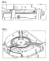
- FIG. 1 shows the rear region of the evaporator module housing 10, in which the fan 20 is arranged.
- the fan 20, consisting of impeller and motor, is arranged in a fan housing 30.
- the entire fan housing 30 with all the air flow influencing elements, such as recesses, air guide elements, etc. is added as an independent module in the recess 14 in the wall 12 of the evaporator module housing 10.
- the fan housing 30 with fan can be easily removed from the evaporator module housing 10 or from its recess 14 of the wall 12.
- FIG. 2 shows the arrangement according to FIG. 1 in a view from diagonally above.
- the recess 14 is bounded by two plate-shaped projections 16 which in FIG. 4 are shown enlarged. Between these plate-shaped projections 16 and the fan housing 30 vibration damper 40 are arranged, which are designed as thermoplastic elastomer elements.
- the vibration damper 40 are configured substantially plate-shaped and latched on the one hand with the fan housing 30 and on the other hand with the plate-shaped projections 16 of the evaporator module housing 10.
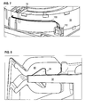
- FIG. 5 shows the arrangement according to FIG. 4 with inserted vibration damper 40th
- FIG. 3 shows in a detailed view the inverted U-shaped edge region 32 of the fan housing, on which a seal 60 is attached.
- the seal 60 is a cross-sectional view in FIG FIG. 8 represented, it serves with its seat on the housing edge to that with a very small contact force a seal to the inner container of the device is made possible.
- the seal 60 has a specially designed profile, which consists of two approximately at right angles to each other extending lips, which are pressed against the inner container.
- the seal 60 further has a groove-shaped recess which is attached to the edge region 32 of the fan housing 30 and fixed there via a latching connection 34.
- a latching nose 34 At the edge region 32 is a latching nose 34, which rests in a recess of the seal 60 and thus holds the seal 60 at the edge region 32.
- the seal is a mirror image, so that an assembly is possible without paying attention to the geometry.
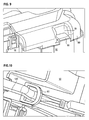
- FIG. 6 shows the fan housing 30 from the side facing away from the interior of the evaporator module housing 10 side.
- the fan assembly in the fan housing 30 via a three-armed holding part 70, of the two arms 72, 74 are accommodated by means of a fork-shaped holding geometry in a correspondingly shaped receptacle on the fan housing 30.
- the third arm 76 is held by means of a special snap geometry. This additionally serves as a cable receptacle for the fan cable 100 and further has a strain relief for the cable 100.
- FIG. 7 shows the coupling 110 of the fan or the fan 100. As is apparent from FIG. 7 shows, this is fixedly mounted in a wall of the fan housing 30, so that a particularly compact assembly is formed and free-hanging cable ends are avoided.
- the production of the connector and the installation of the fan assemblies can be performed easily in confined spaces. The compactness facilitates handling with the module.
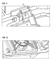
- FIG. 9 shows a arranged on the back of the evaporator module housing 10 left and right above holding geometry, the one from the evaporator module housing 10 arranged tab 18 which engages in a recess 81 of the evaporator module housing cover 80.
- the holder 18 serves to control the overall height of the evaporator module. This is particularly important because polystyrene parts are often prone to dimensional deviations. With the height control, which is realized by the fact that the tab 11 can engage in the recess 81, it is ensured that only modules that have sufficient insulation and at the same time comply with the maximum installation height, reach for installation in the device.
- FIG. 10 shows an eyelet 90 for receiving the suction line 120.
- This eyelet 90 and the headband also makes mounting in a recessed, narrow guide channel possible.
- the eyelet 90 and the hook is latched to the evaporator module housing 10, wherein so-called shield plates can be provided, which close the through holes again. In this way, protection against unwanted air return is achieved.
- FIG. 11 shows the evaporator module housing 10 with a recess 19 for carrying a plurality of cables 140 in the evaporator module housing 10.
- the receiving geometry is used for positioning, the recording for an excess length on the sensor cable and the strain relief of the cable set.
- the cables 140 have a fixed length position to each other. The inclusion of only one cable automatically results in the other of the inward-guided cable lengths.
- the excess length of the sensor cable is required in case of repair.
- the soldering in of the new sensor head may only be carried out outside the device.
- FIG. 11 Another feature of in FIG. 11 The arrangement shown is the strain relief of the cable.
- evaporator module housing 10 For positioning the evaporator module housing 10 in the inner container of the device are on the back of several geometric shapes 150, as is apparent from FIG. 12 is apparent. These position the module 10 horizontally centered and vertically at the correct height, even if the device is located on the side during installation.
- the present evaporator module housing is particularly suitable as a no-frost evaporator module for built-in freezers.
- the use is not limited to this application.
Landscapes
- Engineering & Computer Science (AREA)
- Chemical & Material Sciences (AREA)
- Combustion & Propulsion (AREA)
- Physics & Mathematics (AREA)
- Mechanical Engineering (AREA)
- Thermal Sciences (AREA)
- General Engineering & Computer Science (AREA)
- Cold Air Circulating Systems And Constructional Details In Refrigerators (AREA)
Applications Claiming Priority (2)
| Application Number | Priority Date | Filing Date | Title |
|---|---|---|---|
| DE202007009036 | 2007-06-28 | ||
| DE202007015310U DE202007015310U1 (de) | 2007-06-28 | 2007-11-05 | Verdampfermodul sowie Kühl- und/oder Gefriergerät mit einem derartigen Verdampfermodul |
Publications (1)
| Publication Number | Publication Date |
|---|---|
| EP2009376A1 true EP2009376A1 (fr) | 2008-12-31 |
Family
ID=39942455
Family Applications (1)
| Application Number | Title | Priority Date | Filing Date |
|---|---|---|---|
| EP08011598A Withdrawn EP2009376A1 (fr) | 2007-06-28 | 2008-06-26 | Module d'évaporateur ainsi qu'appareil de réfrigération et/ou de congélation doté d'un tel module d'évaporateur |
Country Status (2)
| Country | Link |
|---|---|
| EP (1) | EP2009376A1 (fr) |
| DE (1) | DE202007015310U1 (fr) |
Cited By (2)
| Publication number | Priority date | Publication date | Assignee | Title |
|---|---|---|---|---|
| CN104105932A (zh) * | 2012-02-09 | 2014-10-15 | Bsh博世和西门子家用电器有限公司 | 具有通风器的制冷器具 |
| US10571183B2 (en) | 2016-03-09 | 2020-02-25 | Qingdao Haier Joint Stock Co., Ltd | Refrigerator and branching air supply device for refrigerator |
Families Citing this family (5)
| Publication number | Priority date | Publication date | Assignee | Title |
|---|---|---|---|---|
| DE102009045343A1 (de) * | 2009-10-05 | 2011-04-07 | BSH Bosch und Siemens Hausgeräte GmbH | Kältegerät mit Ventilatorbaugruppe |
| DE102009045342A1 (de) * | 2009-10-05 | 2011-04-07 | BSH Bosch und Siemens Hausgeräte GmbH | Kältegerät mit Ventilator |
| US9869505B2 (en) * | 2010-12-16 | 2018-01-16 | Heatcraft Refrigeration Products, Llc | Evaporator with replaceable fan venturi ring |
| US10041737B2 (en) | 2010-12-16 | 2018-08-07 | Heatcraft Refrigeration Products, Llc | Evaporator |
| CN105605848B (zh) * | 2016-03-09 | 2018-04-20 | 青岛海尔股份有限公司 | 冰箱及用于冰箱的分路送风装置 |
Citations (5)
| Publication number | Priority date | Publication date | Assignee | Title |
|---|---|---|---|---|
| JPH11108546A (ja) * | 1997-10-08 | 1999-04-23 | Hoshizaki Electric Co Ltd | 断熱箱体における開口形成構造 |
| JP2002340464A (ja) * | 2001-05-16 | 2002-11-27 | Hoshizaki Electric Co Ltd | 冷却貯蔵庫 |
| JP2003009470A (ja) * | 2001-06-21 | 2003-01-10 | Toshiba Corp | ファンモータ |
| KR20040091475A (ko) * | 2003-04-22 | 2004-10-28 | 엘지전자 주식회사 | 냉장고용 팬모터의 리드와이어 걸이구조 |
| DE202005014370U1 (de) | 2005-09-12 | 2006-07-20 | BSH Bosch und Siemens Hausgeräte GmbH | No-Frost-Kältegerät |
-
2007
- 2007-11-05 DE DE202007015310U patent/DE202007015310U1/de not_active Expired - Lifetime
-
2008
- 2008-06-26 EP EP08011598A patent/EP2009376A1/fr not_active Withdrawn
Patent Citations (5)
| Publication number | Priority date | Publication date | Assignee | Title |
|---|---|---|---|---|
| JPH11108546A (ja) * | 1997-10-08 | 1999-04-23 | Hoshizaki Electric Co Ltd | 断熱箱体における開口形成構造 |
| JP2002340464A (ja) * | 2001-05-16 | 2002-11-27 | Hoshizaki Electric Co Ltd | 冷却貯蔵庫 |
| JP2003009470A (ja) * | 2001-06-21 | 2003-01-10 | Toshiba Corp | ファンモータ |
| KR20040091475A (ko) * | 2003-04-22 | 2004-10-28 | 엘지전자 주식회사 | 냉장고용 팬모터의 리드와이어 걸이구조 |
| DE202005014370U1 (de) | 2005-09-12 | 2006-07-20 | BSH Bosch und Siemens Hausgeräte GmbH | No-Frost-Kältegerät |
Cited By (5)
| Publication number | Priority date | Publication date | Assignee | Title |
|---|---|---|---|---|
| CN104105932A (zh) * | 2012-02-09 | 2014-10-15 | Bsh博世和西门子家用电器有限公司 | 具有通风器的制冷器具 |
| US20150047386A1 (en) * | 2012-02-09 | 2015-02-19 | BSH Bosch und Siemens Hausgeräte GmbH | Refrigerating device comprising a fan |
| CN104105932B (zh) * | 2012-02-09 | 2016-08-31 | Bsh家用电器有限公司 | 具有通风器的制冷器具 |
| US9528742B2 (en) | 2012-02-09 | 2016-12-27 | BSH Hausgeräte GmbH | Refrigerating device comprising a fan |
| US10571183B2 (en) | 2016-03-09 | 2020-02-25 | Qingdao Haier Joint Stock Co., Ltd | Refrigerator and branching air supply device for refrigerator |
Also Published As
| Publication number | Publication date |
|---|---|
| DE202007015310U1 (de) | 2008-11-06 |
Similar Documents
| Publication | Publication Date | Title |
|---|---|---|
| EP2009376A1 (fr) | Module d'évaporateur ainsi qu'appareil de réfrigération et/ou de congélation doté d'un tel module d'évaporateur | |
| EP2354709B1 (fr) | Pompe à chaleur air/eau pour un montage extérieur | |
| EP1844637B1 (fr) | Dispositif pour refroidir des unites modulaires electroniques dans des armoires d'equipements et de reseau | |
| EP2529070B1 (fr) | Appareil de réfrigération, notamment pour un armoire de distribution | |
| DE102008051085A1 (de) | Batterieanordnung | |
| EP2904273B1 (fr) | Ventilateur et élément de support associé | |
| DE102009057129A1 (de) | Belüftungsvorrichtung für Komponenten eines Elektronik- oder Computerschranks | |
| EP3623715A2 (fr) | Système de boites murales pour un système d'aération | |
| DE202019002009U1 (de) | Adapter für Klimageräte | |
| DE102008050376A1 (de) | Wärmetauscher für ein Klimatisierungsgerät | |
| EP3101350A1 (fr) | Boitier de ventilateur pour hotte aspirante, unite de ventilateur pour hotte aspirante et hotte aspirante | |
| WO2022157046A1 (fr) | Procédé d'installation de caméra sur une paroi de compartiment intérieur d'appareil ménager, et appareil ménager associé | |
| EP3059505B1 (fr) | Caisson de ventilateur pour hotte aspirante et hotte aspirante | |
| EP2114200A2 (fr) | Pupitre de commande | |
| EP2667126A2 (fr) | Appareil de réfrigération et/ou de congélation | |
| DE102013101507A1 (de) | Kombinierter Kabel- und Luftkanal für die Schaltschrankklimatisierung sowie ein entsprechender Schaltschrank | |
| EP2486348B1 (fr) | Appareil de réfrigération doté d'un bloc ventilateur | |
| EP3447413B1 (fr) | Appareil de réfrigération et/ou de congélation | |
| DE102004030236B3 (de) | Geräteträger für ein Kraftfahrzeug | |
| DE102008010182A1 (de) | Gehäuse für eine Gasfördereinrichtung | |
| DE202015104200U1 (de) | Adaptergehäuse für Zusatzgeräte eines Stromzählers und Stromzähleranordnung mit einem solchen Adaptergehäuse | |
| EP2525176A2 (fr) | Appareil de réfrigération et/ou de congélation | |
| EP2325586A2 (fr) | Agencement de retenue pour un ventilateur, bloc et appareil de refroidissement et/ou de congélation | |
| DE8305869U1 (de) | Lüftereinschub | |
| EP4576967A1 (fr) | Agencement de refroidissement d'un convertisseur de pompe à chaleur |
Legal Events
| Date | Code | Title | Description |
|---|---|---|---|
| PUAI | Public reference made under article 153(3) epc to a published international application that has entered the european phase |
Free format text: ORIGINAL CODE: 0009012 |
|
| AK | Designated contracting states |
Kind code of ref document: A1 Designated state(s): AT BE BG CH CY CZ DE DK EE ES FI FR GB GR HR HU IE IS IT LI LT LU LV MC MT NL NO PL PT RO SE SI SK TR |
|
| AX | Request for extension of the european patent |
Extension state: AL BA MK RS |
|
| 17P | Request for examination filed |
Effective date: 20090609 |
|
| AKX | Designation fees paid |
Designated state(s): DE ES FR IT |
|
| 17Q | First examination report despatched |
Effective date: 20090715 |
|
| STAA | Information on the status of an ep patent application or granted ep patent |
Free format text: STATUS: THE APPLICATION IS DEEMED TO BE WITHDRAWN |
|
| 18D | Application deemed to be withdrawn |
Effective date: 20170103 |