EP2009385B1 - Feuerwerksständer - Google Patents
Feuerwerksständer Download PDFInfo
- Publication number
- EP2009385B1 EP2009385B1 EP07012620A EP07012620A EP2009385B1 EP 2009385 B1 EP2009385 B1 EP 2009385B1 EP 07012620 A EP07012620 A EP 07012620A EP 07012620 A EP07012620 A EP 07012620A EP 2009385 B1 EP2009385 B1 EP 2009385B1
- Authority
- EP
- European Patent Office
- Prior art keywords
- firework
- fireworks
- holders
- main body
- opening
- Prior art date
- Legal status (The legal status is an assumption and is not a legal conclusion. Google has not performed a legal analysis and makes no representation as to the accuracy of the status listed.)
- Not-in-force
Links
- 238000010304 firing Methods 0.000 description 7
- 238000003780 insertion Methods 0.000 description 3
- 230000037431 insertion Effects 0.000 description 3
- 239000005022 packaging material Substances 0.000 description 2
- 239000003973 paint Substances 0.000 description 2
- 239000000463 material Substances 0.000 description 1
- 238000012856 packing Methods 0.000 description 1
Images


Classifications
-
- F—MECHANICAL ENGINEERING; LIGHTING; HEATING; WEAPONS; BLASTING
- F42—AMMUNITION; BLASTING
- F42B—EXPLOSIVE CHARGES, e.g. FOR BLASTING, FIREWORKS, AMMUNITION
- F42B4/00—Fireworks, i.e. pyrotechnic devices for amusement, display, illumination or signal purposes
- F42B4/20—Fireworks, i.e. pyrotechnic devices for amusement, display, illumination or signal purposes characterised by having holder or support other than casing, e.g. whirler or spike support
Definitions
- the invention relates to a firework stand, through which the fireworks paint different fire images in the sky.
- the conventional fireworks display usually consists of launcher, a rack and a Zündfaden, such as launch tube for fireworks TW 347074 , Fireworks stand out TW 419056 and firing pipe for fireworks TW 496515 is known.
- FIG. 1 shows a conventional firework display stand, whose frame 11 carries a plurality of fireworks 12, which are vertical and are connected to each other via the Zündfaden 13.
- the firing thread 13 extends from the frame 11 and forms a firing end 14.
- the fireworks are fired sequentially, thereby firing the effect bodies 15 into the sky, so that a fire image is produced. Since the fireworks 12 are vertical, the fire image is limited thereby.
- the invention has for its object to provide a firework stand, through which the fireworks paint different fire images in the sky.
- a firework stand which has an upper disc with insertion openings and a lower disc with insertion openings, wherein the orientation of the mutual insertion openings can be selected such that inserted fireworks have an angle of inclination.
- the fireworks display according to the invention which consists of a main body having a bottom and a bearing surface for fireworks, wherein the bottom and the contact surface include a non-rectangular angle.
- the fireworks are attached to the contact surface and thus have a tilt angle.
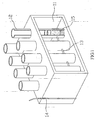
- the firework display stand 2 consists of a main body 21, which has an underside 22, which may lie on the surface of an object, and a firework support surface 3, wherein the bottom 22 and the abutment surface 23 include a non-rectangular angle.
- the main body 21 is tubular and has at the top 24 and the bottom 22 a first opening 241 and a second opening 221, wherein the first opening 241 is larger than the second opening 221.
- the first and second openings 241 and 221 may be round. They can also be polygonal, as in FIG. 4 is shown to be oval or curved.
- the undersides of the fireworks 3 can as in FIG. 3 (A) be formed or lie with the bottom 22 on the same plane as in FIG. 3 (B) is shown.
- the fireworks 3 can be fixed to the inside or outside of the main body 21.
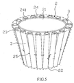
- the fireworks are distributed on the inside and outside of the main body 21 (in FIG. 5 the fireworks are attached only to the outside of the main body 21) and each forming one layer.
- the fireworks form two layers.
- the fireworks 3 extend in the longitudinal direction of the contact surface 23 and are connected to each other via a Zündfaden 25.
- the Fertechnikspian 3 are enclosed by a packaging material 26, as in FIG. 6 is shown.
- the ignition thread 25 extends from the packaging material 26 and forms a firing end 27.
- the first opening 241 is smaller than the second opening 221, whereby the fireworks 21, the fire image in FIG. 9 can generate.
- the fireworks 21 deviate from the longitudinal direction of the contact surface 23, whereby the fireworks 21, the fire image in FIG. 11 can generate.
Landscapes
- Engineering & Computer Science (AREA)
- General Engineering & Computer Science (AREA)
- Toys (AREA)
- Buffer Packaging (AREA)
- Gyroscopes (AREA)
- Optical Modulation, Optical Deflection, Nonlinear Optics, Optical Demodulation, Optical Logic Elements (AREA)
Description
- Die Erfindung betrifft ein Feuerwerksständer, durch den die Feuerwerkskörper unterschiedliche Feuerbilder in den Himmel malen können.
- Der herkömmliche Feuerwerksständer besteht üblicherweise aus Abschußrohren, einem Gestell und einem Zündfaden, wie Abschußrohr für Feuerwerk aus
TW 347074 TW 419056 TW 496515 -
Figur 1 zeigt einen herkömmlichen Feuerwerksständer, dessen Gestell 11 eine Vielzahl von Feuerwerkskörpern 12 trägt, die vertikal stehen und über den Zündfaden 13 miteinander verbunden sind. Der Zündfaden 13 erstreckt sich aus dem Gestell 11 und bildet ein Zündende 14. Wenn das Zündende 14 gezündet wird, werden die Feuerwerkskörper nacheinander angezündet, wodurch die Effektkörper 15 in den Himmel geschossen werden, so dass ein Feuerbild erzeugt wird. Da die Feuerwerkskörper 12 vertikal stehen, ist das Feuerbild dadurch begrenzt. - Der Erfindung liegt die Aufgabe zugrunde, einen Feuerwerksständer zu schaffen, durch den die Feuerwerkskörper unterschiedliche Feuerbilder in den Himmel malen können.
- Aus
JP 02 122 997 U - Die vorgenannte Aufgabe wird durch den erfindungsgemäßen Feuerwerksständer gelöst, der aus einem Hauptkörper besteht, der eine Unterseite und eine Anlagefläche für Feuerwerkskörper aufweist, wobei die Unterseite und die Anlagefläche einen nichtrechtwinkligen Winkel einschließen. Die Feuerwerkskörper sind an der Anlagefläche befestigt und haben somit einen Neigungswinkel.
-
- Figur 1
- eine perspektivische Darstellung der Erfindung,
- Figur 2
- eine perspektivische Darstellung des ersten Ausführungsbeispiels der Erfindung,
- Figur
- 3(A) und 3 (B) Schnittdarstellungen des ersten Ausführungsbeispiels der Erfindung,
- Figur 4
- eine perspektivische Darstellung des zweiten Ausführungsbeispiels der Erfindung,
- Figur 5
- eine perspektivische Darstellung des dritten Ausführungsbeispiels der Erfindung,
- Figur 6
- eine perspektivische Darstellung des vierten Ausführungsbeispiels der Erfindung,
- Figur 7
- eine Darstellung des Feuerbildes,
- Figur 8
- eine perspektivische Darstellung des fünften Ausführungsbeispiels der Erfindung,
- Figur 9
- eine Darstellung eines weiteren Feuerbildes,
- Figur 10
- eine perspektivische Darstellung des sechsten Ausführungsbeispiels der Erfindung,
- Figur 11
- eine Darstellung eines nochmals weiteren Feuerbildes.
- Wie aus den
Figuren 2 und3(A) ersichtlich ist, besteht der erfindungsgemäße Feuerwerksständer 2 aus einem Hauptkörper 21, der eine Unterseite 22, die auf der Oberfläche eines Gegenstandes liegen kann, und eine Anlagefläche 23 für Feuerwerkskörper 3 aufweist, wobei die Unterseite 22 und die Anlagefläche 23 einen nichtrechtwinkligen Winkel einschließen. Im vorliegenden Ausführungsbeispiel ist der Hauptkörper 21 rohrförmig ausgebildet und weist an der Oberseite 24 und der Unterseite 22 eine erste Öffnung 241 und eine zweite Öffnung 221 auf, wobei die erste Öffnung 241 größer ist als die zweite Öffnung 221. Die erste und zweite Öffnung 241 und 221 können rund ausgebildet sein. Sie können auch vielkantig, wie inFigur 4 dargestellt ist, ovalförmig oder kurvenförmig ausgebildet sein. Die Unterseiten der Feuerwerkskörper 3 können wie inFigur 3(A) ausgebildet sein oder mit der Unterseite 22 auf der gleichen Ebene liegen, wie es inFigur 3(B) dargestellt ist. - Die Feuerwerkskörper 3 können an der Innenseite oder Außenseite des Hauptkörpers 21 befestigt werden. In
Figur 2 sind die Feuerwerkskörper an der Innenseite und Außenseite des Hauptkörpers 21 verteilt (inFigur 5 sind die Feuerwerkskörper nur an derAußenseite des Hauptkörpers 21 befestigt) und jeweils eine Lage bilden. (InFigur 6 bilden die Feuerwerkskörper zwei Lagen.) Die Feuerwerkskörper 3 erstrecken sich in der Längsrichtung der Anlagefläche 23 und sind über einen Zündfaden 25 miteinander verbunden. Die Ferwerkskörper 3 werden von einem Verpackungsmaterial 26 umschlossen, wie es inFigur 6 dargestellt ist. Der Zündfaden 25 erstreckt sich aus dem Verpackungsmaterial 26 und bildet ein Zündende 27. - Wenn das Zündende 27 gezündet wird, werden die Feuerwerkskörper nacheinander angezündet und in den Himmel geschossen, wodurch ein Feuerbild erzeugt wird, wie es in
Figur 7 dargestellt ist. - Durch Änderung der Größe der Öffnungen kann ein unterschiedliches Feuerbild erzeugt werden. In
Figur 8 ist die erste Öffnung 241 kleiner als die zweite Öffnung 221, wodurch die Feuerwerkskörper 21 das Feuerbild inFigur 9 erzeugen können. Durch Änderung der Anordnung der Feuerwerkskörper 21 kann auch ein unterschiedliches Feuerbild erzeugt werden. InFigur 10 weichen die Feuerwerkskörper 21 von der Längsrichtung der Anlagefläche 23 ab, wodurch die Feuerwerkskörper 21 das Feuerbild inFigur 11 erzeugen können. -
- 11
- Gestell
- 12
- Feuerwerkskörper
- 13
- Zündfaden
- 14
- Zündende
- 15
- Effektkörper
- 2
- Feuerwerksständer
- 21
- Hauptkörper
- 22
- Unterseite
- 221
- zweite Öffnung
- 23
- Anlagefläche
- 24
- Oberseite
- 241
- erste Öffnung
- 25
- Zündfaden
- 26
- Verpackungsmaterial
- 27
- Zündende
- 3
- Feuerwerkskörper
Claims (5)
- Feuerwerksständer
mit einem Hauptkörper (21) und mit Feuerwerkskörpern die einen Neigungswinkel haben, dadurch gekennzeichnet dass der Haupthörper rohrförmig ist und eine Oberseite (24) mit einer ersten Öffnung (241), eine Unterseite (22) mit einer zweiten Öffnung (221) und eine Anlagefläche (23) für Feuerwerkskörper (3) aufweist,
wobei die erste Öffnung (241) kleiner oder größer als die zweite Öffnung (221) ist und daher Unterseite (22) und Anlagefläche (23) einen nicht-rechtwinkligen Winkel einschließen, und
wobei die Feuerwerkskörper (3) an der Anlagefläche (23) des rohrförmigen Hauptkörpers (21) befestigt sind. - Feuerwerksständer nach Anspruch 1, dadurch gekennzeichnet, dass die erste und zweite Öffnung (221, 241) rund, vielkantig, ovalförmig oder kurvenförmig ausgebildet sind.
- Feuerwerksständer nach Anspruch 1 oder 2, dadurch gekennzeichnet, dass die Feuerwerkskörper (3) an der Innenseite und/oder an der Außenseite des Hauptkörpers (21) befestigt sind und eine oder mehr als eine Lage bilden.
- Feuerwerksständer nach einem der Ansprüche 1 bis 3, dadurch gekennzeichnet, dass die Unterseiten der Feuerwerkskörper (3) mit der Unterseite (22) des Hauptkörpers (21) auf der gleichen Ebene liegen.
- Feuerwerksständer nach einem der vorhergehenden Ansprüche, dadurch gekennzeichnet, dass die Feuerwerkskörper (3) sich in Längsrichtung der Anlagefläche (23) erstrecken oder von dieser abweichen.
Priority Applications (4)
| Application Number | Priority Date | Filing Date | Title |
|---|---|---|---|
| EP07012620A EP2009385B1 (de) | 2007-06-27 | 2007-06-27 | Feuerwerksständer |
| DE502007003602T DE502007003602D1 (de) | 2007-06-27 | 2007-06-27 | Feuerwerksständer |
| ES07012620T ES2345117T3 (es) | 2007-06-27 | 2007-06-27 | Soporte pirotecnico. |
| AT07012620T ATE466249T1 (de) | 2007-06-27 | 2007-06-27 | Feuerwerksständer |
Applications Claiming Priority (1)
| Application Number | Priority Date | Filing Date | Title |
|---|---|---|---|
| EP07012620A EP2009385B1 (de) | 2007-06-27 | 2007-06-27 | Feuerwerksständer |
Publications (2)
| Publication Number | Publication Date |
|---|---|
| EP2009385A1 EP2009385A1 (de) | 2008-12-31 |
| EP2009385B1 true EP2009385B1 (de) | 2010-04-28 |
Family
ID=38690554
Family Applications (1)
| Application Number | Title | Priority Date | Filing Date |
|---|---|---|---|
| EP07012620A Not-in-force EP2009385B1 (de) | 2007-06-27 | 2007-06-27 | Feuerwerksständer |
Country Status (4)
| Country | Link |
|---|---|
| EP (1) | EP2009385B1 (de) |
| AT (1) | ATE466249T1 (de) |
| DE (1) | DE502007003602D1 (de) |
| ES (1) | ES2345117T3 (de) |
Families Citing this family (1)
| Publication number | Priority date | Publication date | Assignee | Title |
|---|---|---|---|---|
| NL2002546C2 (nl) | 2009-02-20 | 2010-08-24 | Gerard Willem Johannes Broekhoff | Houder voor consumenten vuurwerk. |
Family Cites Families (5)
| Publication number | Priority date | Publication date | Assignee | Title |
|---|---|---|---|---|
| US2053454A (en) * | 1936-03-28 | 1936-09-08 | Whiteside Robert Banning | Fireworks tube container |
| JPH087278Y2 (ja) * | 1989-03-13 | 1996-03-04 | 五洋貿易株式会社 | 飛走花火発射台 |
| DE9216456U1 (de) * | 1992-12-03 | 1993-02-04 | Pyro-Chemie Hermann Weber & Co GmbH, 5208 Eitorf | Feuerwerksraketenanordnung |
| JP2000283697A (ja) * | 1999-03-30 | 2000-10-13 | Isamu Kato | 筒形花火 |
| US20030070572A1 (en) * | 2001-10-12 | 2003-04-17 | Hua Ken Tang | Fireworks holder with remote control firing |
-
2007
- 2007-06-27 AT AT07012620T patent/ATE466249T1/de active
- 2007-06-27 DE DE502007003602T patent/DE502007003602D1/de not_active Expired - Fee Related
- 2007-06-27 ES ES07012620T patent/ES2345117T3/es active Active
- 2007-06-27 EP EP07012620A patent/EP2009385B1/de not_active Not-in-force
Also Published As
| Publication number | Publication date |
|---|---|
| ATE466249T1 (de) | 2010-05-15 |
| ES2345117T3 (es) | 2010-09-15 |
| EP2009385A1 (de) | 2008-12-31 |
| DE502007003602D1 (de) | 2010-06-10 |
Similar Documents
| Publication | Publication Date | Title |
|---|---|---|
| DE202007008984U1 (de) | Feuerwerksständer | |
| DE2437535C3 (de) | Ausstoßbarer Nebeltopf für hochbeanspruchte Geschosse | |
| DE2902145A1 (de) | Patronenhuelse | |
| WO2016005136A1 (de) | Magazin zur aufbewahrung stabförmiger werkstücke für eine werkzeugmaschine | |
| EP2009385B1 (de) | Feuerwerksständer | |
| DE29619626U1 (de) | Dartscheibe | |
| EP2113740B1 (de) | Feuerwerk | |
| DE2537373A1 (de) | Verfahren zum befestigen eines rohres in einer bohrung durch explosiv- schweissen | |
| DE202008005963U1 (de) | Feuerwerk | |
| DE3730158C2 (de) | ||
| DE3835711A1 (de) | Steuerstab zur beeinflussung der reaktivitaet eines kernreaktors und anordnung mehrerer dieser steuerstaebe zu einem steuerelement | |
| DE3542051A1 (de) | Geschoss mit wirkkoerpern | |
| EP0504771A2 (de) | Vorrichtung zur Aufbewahrung von CD-Kassetten | |
| DE102006050130A1 (de) | Geschossfestes Plattenmaterial | |
| DE102008015014B4 (de) | Kältemittelkompressoranordnung und Verfahren zum Herstellen einer Kältemittelkompressoranordnung | |
| DE3917662C2 (de) | Mine | |
| DE29909162U1 (de) | Feuerwerksrakete | |
| DE2403589A1 (de) | Treibpulverblock insbesondere fuer artilleriegeschosse | |
| DE1284171B (de) | Feder aus uebereinandergeschichteten gewoelbten Scheiben | |
| DE4336335A1 (de) | Schutzeinrichtung für Sensoren | |
| DE202009004447U1 (de) | Halterung | |
| DE1578168C (de) | Schrotpatroneneinsatz | |
| DE102022125641A1 (de) | Kerzenanordnung | |
| DE102021106486A1 (de) | Bodenteil zur Aufnahme eines hohlen Feuerwerksgrundkörpers sowie Feuerwerksbatterie | |
| DE102018120699A1 (de) | Abschussrampe für Feuerwerksraketen |
Legal Events
| Date | Code | Title | Description |
|---|---|---|---|
| PUAI | Public reference made under article 153(3) epc to a published international application that has entered the european phase |
Free format text: ORIGINAL CODE: 0009012 |
|
| 17P | Request for examination filed |
Effective date: 20080418 |
|
| AK | Designated contracting states |
Kind code of ref document: A1 Designated state(s): AT BE BG CH CY CZ DE DK EE ES FI FR GB GR HU IE IS IT LI LT LU LV MC MT NL PL PT RO SE SI SK TR |
|
| AX | Request for extension of the european patent |
Extension state: AL BA HR MK RS |
|
| AKX | Designation fees paid |
Designated state(s): AT BE BG CH CY CZ DE DK EE ES FI FR GB GR HU IE IS IT LI LT LU LV MC MT NL PL PT RO SE SI SK TR |
|
| GRAP | Despatch of communication of intention to grant a patent |
Free format text: ORIGINAL CODE: EPIDOSNIGR1 |
|
| GRAS | Grant fee paid |
Free format text: ORIGINAL CODE: EPIDOSNIGR3 |
|
| GRAA | (expected) grant |
Free format text: ORIGINAL CODE: 0009210 |
|
| AK | Designated contracting states |
Kind code of ref document: B1 Designated state(s): AT BE BG CH CY CZ DE DK EE ES FI FR GB GR HU IE IS IT LI LT LU LV MC MT NL PL PT RO SE SI SK TR |
|
| REG | Reference to a national code |
Ref country code: GB Ref legal event code: FG4D Free format text: NOT ENGLISH |
|
| REG | Reference to a national code |
Ref country code: CH Ref legal event code: EP |
|
| REG | Reference to a national code |
Ref country code: IE Ref legal event code: FG4D Free format text: LANGUAGE OF EP DOCUMENT: GERMAN |
|
| REF | Corresponds to: |
Ref document number: 502007003602 Country of ref document: DE Date of ref document: 20100610 Kind code of ref document: P |
|
| REG | Reference to a national code |
Ref country code: NL Ref legal event code: VDEP Effective date: 20100428 |
|
| REG | Reference to a national code |
Ref country code: ES Ref legal event code: FG2A Ref document number: 2345117 Country of ref document: ES Kind code of ref document: T3 |
|
| LTIE | Lt: invalidation of european patent or patent extension |
Effective date: 20100428 |
|
| PG25 | Lapsed in a contracting state [announced via postgrant information from national office to epo] |
Ref country code: SE Free format text: LAPSE BECAUSE OF FAILURE TO SUBMIT A TRANSLATION OF THE DESCRIPTION OR TO PAY THE FEE WITHIN THE PRESCRIBED TIME-LIMIT Effective date: 20100428 Ref country code: NL Free format text: LAPSE BECAUSE OF FAILURE TO SUBMIT A TRANSLATION OF THE DESCRIPTION OR TO PAY THE FEE WITHIN THE PRESCRIBED TIME-LIMIT Effective date: 20100428 Ref country code: LT Free format text: LAPSE BECAUSE OF FAILURE TO SUBMIT A TRANSLATION OF THE DESCRIPTION OR TO PAY THE FEE WITHIN THE PRESCRIBED TIME-LIMIT Effective date: 20100428 |
|
| REG | Reference to a national code |
Ref country code: IE Ref legal event code: FD4D |
|
| PG25 | Lapsed in a contracting state [announced via postgrant information from national office to epo] |
Ref country code: FI Free format text: LAPSE BECAUSE OF FAILURE TO SUBMIT A TRANSLATION OF THE DESCRIPTION OR TO PAY THE FEE WITHIN THE PRESCRIBED TIME-LIMIT Effective date: 20100428 Ref country code: SI Free format text: LAPSE BECAUSE OF FAILURE TO SUBMIT A TRANSLATION OF THE DESCRIPTION OR TO PAY THE FEE WITHIN THE PRESCRIBED TIME-LIMIT Effective date: 20100428 Ref country code: LV Free format text: LAPSE BECAUSE OF FAILURE TO SUBMIT A TRANSLATION OF THE DESCRIPTION OR TO PAY THE FEE WITHIN THE PRESCRIBED TIME-LIMIT Effective date: 20100428 Ref country code: IS Free format text: LAPSE BECAUSE OF FAILURE TO SUBMIT A TRANSLATION OF THE DESCRIPTION OR TO PAY THE FEE WITHIN THE PRESCRIBED TIME-LIMIT Effective date: 20100828 |
|
| BERE | Be: lapsed |
Owner name: HUANG, WEI-CHIH Effective date: 20100630 |
|
| PG25 | Lapsed in a contracting state [announced via postgrant information from national office to epo] |
Ref country code: CY Free format text: LAPSE BECAUSE OF FAILURE TO SUBMIT A TRANSLATION OF THE DESCRIPTION OR TO PAY THE FEE WITHIN THE PRESCRIBED TIME-LIMIT Effective date: 20100609 Ref country code: PL Free format text: LAPSE BECAUSE OF FAILURE TO SUBMIT A TRANSLATION OF THE DESCRIPTION OR TO PAY THE FEE WITHIN THE PRESCRIBED TIME-LIMIT Effective date: 20100428 |
|
| PG25 | Lapsed in a contracting state [announced via postgrant information from national office to epo] |
Ref country code: DK Free format text: LAPSE BECAUSE OF FAILURE TO SUBMIT A TRANSLATION OF THE DESCRIPTION OR TO PAY THE FEE WITHIN THE PRESCRIBED TIME-LIMIT Effective date: 20100428 Ref country code: EE Free format text: LAPSE BECAUSE OF FAILURE TO SUBMIT A TRANSLATION OF THE DESCRIPTION OR TO PAY THE FEE WITHIN THE PRESCRIBED TIME-LIMIT Effective date: 20100428 Ref country code: GR Free format text: LAPSE BECAUSE OF FAILURE TO SUBMIT A TRANSLATION OF THE DESCRIPTION OR TO PAY THE FEE WITHIN THE PRESCRIBED TIME-LIMIT Effective date: 20100729 Ref country code: IE Free format text: LAPSE BECAUSE OF FAILURE TO SUBMIT A TRANSLATION OF THE DESCRIPTION OR TO PAY THE FEE WITHIN THE PRESCRIBED TIME-LIMIT Effective date: 20100428 Ref country code: MC Free format text: LAPSE BECAUSE OF NON-PAYMENT OF DUE FEES Effective date: 20100630 Ref country code: PT Free format text: LAPSE BECAUSE OF FAILURE TO SUBMIT A TRANSLATION OF THE DESCRIPTION OR TO PAY THE FEE WITHIN THE PRESCRIBED TIME-LIMIT Effective date: 20100830 |
|
| PG25 | Lapsed in a contracting state [announced via postgrant information from national office to epo] |
Ref country code: CZ Free format text: LAPSE BECAUSE OF FAILURE TO SUBMIT A TRANSLATION OF THE DESCRIPTION OR TO PAY THE FEE WITHIN THE PRESCRIBED TIME-LIMIT Effective date: 20100428 Ref country code: SK Free format text: LAPSE BECAUSE OF FAILURE TO SUBMIT A TRANSLATION OF THE DESCRIPTION OR TO PAY THE FEE WITHIN THE PRESCRIBED TIME-LIMIT Effective date: 20100428 Ref country code: RO Free format text: LAPSE BECAUSE OF FAILURE TO SUBMIT A TRANSLATION OF THE DESCRIPTION OR TO PAY THE FEE WITHIN THE PRESCRIBED TIME-LIMIT Effective date: 20100428 |
|
| PLBE | No opposition filed within time limit |
Free format text: ORIGINAL CODE: 0009261 |
|
| STAA | Information on the status of an ep patent application or granted ep patent |
Free format text: STATUS: NO OPPOSITION FILED WITHIN TIME LIMIT |
|
| REG | Reference to a national code |
Ref country code: FR Ref legal event code: ST Effective date: 20110228 |
|
| PG25 | Lapsed in a contracting state [announced via postgrant information from national office to epo] |
Ref country code: IT Free format text: LAPSE BECAUSE OF FAILURE TO SUBMIT A TRANSLATION OF THE DESCRIPTION OR TO PAY THE FEE WITHIN THE PRESCRIBED TIME-LIMIT Effective date: 20100428 |
|
| 26N | No opposition filed |
Effective date: 20110131 |
|
| PG25 | Lapsed in a contracting state [announced via postgrant information from national office to epo] |
Ref country code: DE Free format text: LAPSE BECAUSE OF NON-PAYMENT OF DUE FEES Effective date: 20110101 Ref country code: MT Free format text: LAPSE BECAUSE OF FAILURE TO SUBMIT A TRANSLATION OF THE DESCRIPTION OR TO PAY THE FEE WITHIN THE PRESCRIBED TIME-LIMIT Effective date: 20100428 |
|
| PG25 | Lapsed in a contracting state [announced via postgrant information from national office to epo] |
Ref country code: FR Free format text: LAPSE BECAUSE OF NON-PAYMENT OF DUE FEES Effective date: 20100630 |
|
| PG25 | Lapsed in a contracting state [announced via postgrant information from national office to epo] |
Ref country code: BE Free format text: LAPSE BECAUSE OF NON-PAYMENT OF DUE FEES Effective date: 20100630 |
|
| PGFP | Annual fee paid to national office [announced via postgrant information from national office to epo] |
Ref country code: ES Payment date: 20110628 Year of fee payment: 5 |
|
| PGFP | Annual fee paid to national office [announced via postgrant information from national office to epo] |
Ref country code: GB Payment date: 20110628 Year of fee payment: 5 |
|
| REG | Reference to a national code |
Ref country code: CH Ref legal event code: PL |
|
| PG25 | Lapsed in a contracting state [announced via postgrant information from national office to epo] |
Ref country code: LI Free format text: LAPSE BECAUSE OF NON-PAYMENT OF DUE FEES Effective date: 20110630 Ref country code: CH Free format text: LAPSE BECAUSE OF NON-PAYMENT OF DUE FEES Effective date: 20110630 |
|
| PG25 | Lapsed in a contracting state [announced via postgrant information from national office to epo] |
Ref country code: BG Free format text: LAPSE BECAUSE OF FAILURE TO SUBMIT A TRANSLATION OF THE DESCRIPTION OR TO PAY THE FEE WITHIN THE PRESCRIBED TIME-LIMIT Effective date: 20100428 Ref country code: HU Free format text: LAPSE BECAUSE OF FAILURE TO SUBMIT A TRANSLATION OF THE DESCRIPTION OR TO PAY THE FEE WITHIN THE PRESCRIBED TIME-LIMIT Effective date: 20101029 Ref country code: LU Free format text: LAPSE BECAUSE OF NON-PAYMENT OF DUE FEES Effective date: 20100627 |
|
| PG25 | Lapsed in a contracting state [announced via postgrant information from national office to epo] |
Ref country code: TR Free format text: LAPSE BECAUSE OF FAILURE TO SUBMIT A TRANSLATION OF THE DESCRIPTION OR TO PAY THE FEE WITHIN THE PRESCRIBED TIME-LIMIT Effective date: 20100428 |
|
| GBPC | Gb: european patent ceased through non-payment of renewal fee |
Effective date: 20120627 |
|
| PG25 | Lapsed in a contracting state [announced via postgrant information from national office to epo] |
Ref country code: GB Free format text: LAPSE BECAUSE OF NON-PAYMENT OF DUE FEES Effective date: 20120627 |
|
| REG | Reference to a national code |
Ref country code: AT Ref legal event code: MM01 Ref document number: 466249 Country of ref document: AT Kind code of ref document: T Effective date: 20120627 |
|
| PG25 | Lapsed in a contracting state [announced via postgrant information from national office to epo] |
Ref country code: BG Free format text: LAPSE BECAUSE OF FAILURE TO SUBMIT A TRANSLATION OF THE DESCRIPTION OR TO PAY THE FEE WITHIN THE PRESCRIBED TIME-LIMIT Effective date: 20100728 |
|
| REG | Reference to a national code |
Ref country code: ES Ref legal event code: FD2A Effective date: 20131021 |
|
| PG25 | Lapsed in a contracting state [announced via postgrant information from national office to epo] |
Ref country code: ES Free format text: LAPSE BECAUSE OF NON-PAYMENT OF DUE FEES Effective date: 20120628 Ref country code: AT Free format text: LAPSE BECAUSE OF NON-PAYMENT OF DUE FEES Effective date: 20120627 |