EP2009463A2 - Dispositif de sécurité pour un système d'autoprotection automatique - Google Patents
Dispositif de sécurité pour un système d'autoprotection automatique Download PDFInfo
- Publication number
- EP2009463A2 EP2009463A2 EP08010566A EP08010566A EP2009463A2 EP 2009463 A2 EP2009463 A2 EP 2009463A2 EP 08010566 A EP08010566 A EP 08010566A EP 08010566 A EP08010566 A EP 08010566A EP 2009463 A2 EP2009463 A2 EP 2009463A2
- Authority
- EP
- European Patent Office
- Prior art keywords
- radar
- safety device
- safety
- circuit
- ignition
- Prior art date
- Legal status (The legal status is an assumption and is not a legal conclusion. Google has not performed a legal analysis and makes no representation as to the accuracy of the status listed.)
- Granted
Links
Images

Classifications
-
- G—PHYSICS
- G01—MEASURING; TESTING
- G01S—RADIO DIRECTION-FINDING; RADIO NAVIGATION; DETERMINING DISTANCE OR VELOCITY BY USE OF RADIO WAVES; LOCATING OR PRESENCE-DETECTING BY USE OF THE REFLECTION OR RERADIATION OF RADIO WAVES; ANALOGOUS ARRANGEMENTS USING OTHER WAVES
- G01S13/00—Systems using the reflection or reradiation of radio waves, e.g. radar systems; Analogous systems using reflection or reradiation of waves whose nature or wavelength is irrelevant or unspecified
- G01S13/02—Systems using reflection of radio waves, e.g. primary radar systems; Analogous systems
- G01S13/50—Systems of measurement based on relative movement of target
- G01S13/58—Velocity or trajectory determination systems; Sense-of-movement determination systems
-
- F—MECHANICAL ENGINEERING; LIGHTING; HEATING; WEAPONS; BLASTING
- F41—WEAPONS
- F41G—WEAPON SIGHTS; AIMING
- F41G3/00—Aiming or laying means
- F41G3/14—Indirect aiming means
-
- F—MECHANICAL ENGINEERING; LIGHTING; HEATING; WEAPONS; BLASTING
- F42—AMMUNITION; BLASTING
- F42C—AMMUNITION FUZES; ARMING OR SAFETY MEANS THEREFOR
- F42C15/00—Arming-means in fuzes; Safety means for preventing premature detonation of fuzes or charges
- F42C15/40—Arming-means in fuzes; Safety means for preventing premature detonation of fuzes or charges wherein the safety or arming action is effected electrically
- F42C15/42—Arming-means in fuzes; Safety means for preventing premature detonation of fuzes or charges wherein the safety or arming action is effected electrically from a remote location, e.g. for controlled mines or mine fields
-
- G—PHYSICS
- G01—MEASURING; TESTING
- G01S—RADIO DIRECTION-FINDING; RADIO NAVIGATION; DETERMINING DISTANCE OR VELOCITY BY USE OF RADIO WAVES; LOCATING OR PRESENCE-DETECTING BY USE OF THE REFLECTION OR RERADIATION OF RADIO WAVES; ANALOGOUS ARRANGEMENTS USING OTHER WAVES
- G01S7/00—Details of systems according to groups G01S13/00, G01S15/00, G01S17/00
- G01S7/02—Details of systems according to groups G01S13/00, G01S15/00, G01S17/00 of systems according to group G01S13/00
- G01S7/40—Means for monitoring or calibrating
- G01S7/4004—Means for monitoring or calibrating of parts of a radar system
Definitions
- the invention relates to a safety device according to the preamble of claim 1 for an automatic self-protection system.
- the invention has for its object to provide a safety device of the type mentioned, wherein the proof of the system security of the safety device can be realized with relatively simple means to obtain an approval for the AWiSS.
- the security device has the advantage that the realization of the system security is separate from the tasks of the fire control, which consists in achieving a high probability of being hit.
- the radar raw data that is, the radar data in parallel with the computer system of the fire control system, ie. H. the radar Doppler signals, evaluated to detect whether an object is at the speed of a real target in the field of view of the radar.
- the firing circuits of the AWiSS are released, so that, for example, a defensive grenade can be launched.
- the system security is therefore realized by a safety circuit that is possibly made of hardware only.
- the invention advantageously a strict separation between the system safety function, ie the firing clearance, and the task of fire control, ie the firing direction and the firing time given. Only if a firing is released by the security circuit, a countermeasure can be initiated according to the invention by the system computer of the fire control. According to the invention, arming is thus effected only when a threat is detected by the security circuit and firing takes place.
- Fig. 1 schematically illustrates an embodiment of the safety device 10 for an automatic self-protection system.
- the safety device 10 has a radar receiving device 12, which is connected via a radar signal processing device 14 with a distance-effective protection system AWiSS, ie a system controller and fire line 16.
- the AWiSS 16 is connected to an ignition and safety device 18.
- a safety circuit 20 is connected in parallel to the radar signal processing device 14 and the AWiSS 16, which is provided for the evaluation of radar Doppler signals of the radar receiving device 12.
- the security circuit 20 has an output 22, which is provided for the output of threat release signals.
- the AWiSS 16 has an output 24, which is provided for the output of ignition signals, which are generated by the fire control.
- the outputs 22 and 24 are connected together with inputs of an AND gate 30, whose output 32 is connected to the ignition and safety device 18.
- the AND link 30 forms a component of the ignition and safety device 18.
- Fig. 1 an embodiment of the safety device 10 is schematically illustrated in a block diagram, wherein the radar receiving device 12 has a single radar receiving module 34.
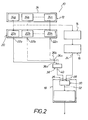
- FIG. 2 an embodiment of the safety device 10, in which the radar receiving device 12, a number of radar receiving modules 34a, 34b, .... 34n has.
- the / each radar receiver module has two radar frequencies, one of which is fixed and the second is switchable for distance measurement.
- Each radar receive module 34a, 34b, .... 34n is interconnected to an associated security circuit 20a, 20b, .... 20n.
- the safety circuits 20a, 20b, .... 20n have outputs 22a, 22b, .... 22n, which are connected together with the inputs 36a, 36b, .... 36n of an OR operation 38.
- the OR link 38 has an output 40 which is connected to the input 26 of the AND link 30 of the ignition and safety device 18.
- the reference numeral 14 is also in Fig. 2 the radar signal processing device and the reference numeral 16 denotes the AWiSS of the safety device 10.
- the operation of the security device 10 is as follows:
- the radar raw data, d. H. the radar Doppler signals are evaluated parallel to the fire line by the safety circuit 20. If a Doppler signal is detected which corresponds to a predetermined target spectrum, the safety circuit 20 generates an enable signal at the output 22. By the ignition and safety device 18, an AND link 30 between the firing clearance - safety circuit 20 - and the pending at the output 24 ignition signal of the fire control is made. Thus, a shot can only be delivered via the fire line if a firing release takes place beforehand by the security circuit 20.
- the AND operation 30 of the ignition and safety device 18 deactivates all ignition circuits by these are switched energy-free, as long as no release signal is present at the output 22.
- the radar provided for the AWiSS 16 uses two radar frequencies per radar reception module 34a, 34b,... 34n, one of the two frequencies being fixed and the second frequency being switchable for distance measurement - as already mentioned.
- the safety device 10 advantageous is the use of two frequencies, because by an independent evaluation of the two frequencies, the reliability of the safety device 10 is further improved.
- Each radar receive module 34a, 34b, .... 34n thus provides sixteen analog raw signals which can be evaluated by the security circuit 20. How many of the raw signals are evaluated by the safety circuit 20 can be determined as desired. The number of raw radar signals evaluated enhances the reliability of the safety device 10.
- the security circuit 20 analyzes at least two of the analog radar channels for existing Doppler frequencies.
- FFT Fast Fourier Transformation
- FPGA an EPROM, that is, hardwired software.
- the special type of signal processing is not relevant according to the invention, but care should be taken that as few processors as possible are used, because a more complex qualification is required when using processors and associated software.
- the ignition lines will be released via the ignition and safety device 18, so that the fire control system can, for example, fire a defensive grenade. Care must be taken to ensure that there are two independent enable signals for a release, ie a release via two separate channels.
- the ignition and safety device 18 locks all safety-relevant signals, so that in the safety device 10 according to the invention, the system security is guaranteed independent of the fire control system.
- the system security can thus be ensured without consideration of the fire control system, so that can advantageously account for a complicated qualification of the software.
- the evaluation circuit may also have a microcontroller, i. H. an evaluation of the radar raw data by a microcontroller is also possible.
- a software-based solution means that the qualification is more expensive;
- the required software is advantageously of a much lower complexity, so that the qualification effort is still much lower than if a qualification of the complete fire control software would have to be performed.
- the Fig. 2 illustrates an embodiment of the safety device 10, consisting of a number of radar receiving modules 34a, 34b, .... 34n, each radar receiving module is associated with a safety circuit 20a, 20b, .... 20n. After each radar receive module at least two channels must be evaluated. A release of the ignition and safety device 18 should take place when there is a threat in one of the radar receiving modules.
- the enable signals of the various radar receiving modules 34a, 34, .... 34n are therefore realized as an OR operation 38.
- a central aspect of the present invention is thus the separation of the Feuerleitrote from the system security.
- the FLR in this case the AWiSS, is generally active all the time: constantly moving objects in the detection area and data are constantly measured calculated for interception, but without actually taking any countermeasures.
- This system security can in the simplest case be a button that the human operator of the system presses on. From this point on the system is "sharp", ie. H. the ignition capacitors of the system are charged and the system is generally put into the condition to initiate a countermeasure.
- the system will also fight targets that it should not combat (eg, civilian objects such as cars, thrown objects, etc.).
- targets eg, civilian objects such as cars, thrown objects, etc.
- the target discriminates against the person who tells the system what a real goal is and what it is not (in fact, if the user presses the trigger button in the case of a positive decision and the system initiates the countermeasure).
- the system is in an unsafe state after the "focus", because the constantly countermeasures calculating system is held only on a reins held by a man.
- An object of the invention is now to "secure the unsecured system", i. H. somehow prevent the system from firing at a non-real target.
- the target distinction which is fed directly by the raw signals of the radar and Doppler sensors, is used for the backup.
- the safety circuit only uses the raw data to decide: it is a real target (eg because it flies fast enough), ie it is completely nonspecific without calculating the trajectory of the projectile.
- the safety circuit generally gives fire clearance. But that does not automatically mean that the system really fires, because the FLR can be used for example.
- B. calculate that the approaching object passes by and a countermeasure is not necessary. Only if the constantly active FLR considers a countermeasure to be necessary due to constant track calculation does it in turn issue a fire command (AND operation) and the countermeasure is actually initiated.
- Both system components ie the FLR and the safety circuit, are fed by the raw data of the radar and Doppler sensors, but while the FLR calculates the tracking data of the approaching bullet and calculates (hypothetical) countermeasures, the safety circuit only uses the same data to determine if it is is generally a real target at all (eg, because it is fast enough, a hand-thrown object usually does not fly fast enough and is sorted out as a non-real target, so to speak).
- the function of the safety circuit is thus taken out of the pure FLR and separated from it. This allows the FLR to be modified without recalibration because the safety circuit remains unchanged.
Landscapes
- Engineering & Computer Science (AREA)
- Radar, Positioning & Navigation (AREA)
- Remote Sensing (AREA)
- General Engineering & Computer Science (AREA)
- Computer Networks & Wireless Communication (AREA)
- Physics & Mathematics (AREA)
- General Physics & Mathematics (AREA)
- Radar Systems Or Details Thereof (AREA)
Applications Claiming Priority (1)
| Application Number | Priority Date | Filing Date | Title |
|---|---|---|---|
| DE102007028677A DE102007028677A1 (de) | 2007-06-21 | 2007-06-21 | Sicherheitsvorrichtung für ein automatisches Selbstschutzsystem |
Publications (3)
| Publication Number | Publication Date |
|---|---|
| EP2009463A2 true EP2009463A2 (fr) | 2008-12-31 |
| EP2009463A3 EP2009463A3 (fr) | 2009-07-22 |
| EP2009463B1 EP2009463B1 (fr) | 2013-04-24 |
Family
ID=39758458
Family Applications (1)
| Application Number | Title | Priority Date | Filing Date |
|---|---|---|---|
| EP08010566.1A Active EP2009463B1 (fr) | 2007-06-21 | 2008-06-11 | Dispositif de sécurité pour un système d'autoprotection automatique |
Country Status (3)
| Country | Link |
|---|---|
| EP (1) | EP2009463B1 (fr) |
| DE (1) | DE102007028677A1 (fr) |
| IL (1) | IL192069A (fr) |
Cited By (1)
| Publication number | Priority date | Publication date | Assignee | Title |
|---|---|---|---|---|
| EP2600172A1 (fr) * | 2011-12-02 | 2013-06-05 | Diehl BGT Defence GmbH & Co.KG | Dispositif de radar |
Families Citing this family (1)
| Publication number | Priority date | Publication date | Assignee | Title |
|---|---|---|---|---|
| RU2560259C1 (ru) * | 2014-02-04 | 2015-08-20 | Виктор Леонидович Семенов | Способ наведения оружия и ракеты на цель и устройство для его реализации |
Citations (3)
| Publication number | Priority date | Publication date | Assignee | Title |
|---|---|---|---|---|
| EP0707220A2 (fr) | 1994-10-13 | 1996-04-17 | Honda Giken Kogyo Kabushiki Kaisha | Module radar et système radar |
| EP1043601A2 (fr) | 1999-04-07 | 2000-10-11 | Volkswagen Aktiengesellschaft | Procédé radar pour mesurer des distances et des vitesses relatives entre un véhicule et des obstacles |
| US6782793B1 (en) | 1990-10-05 | 2004-08-31 | Honeywell Aerospatiale Inc. | Active armor protection system for armored vehicles |
Family Cites Families (2)
| Publication number | Priority date | Publication date | Assignee | Title |
|---|---|---|---|---|
| DE4426014B4 (de) * | 1994-07-22 | 2004-09-30 | Diehl Stiftung & Co.Kg | System zum Schutz eines Zieles gegen Flugkörper |
| US5917442A (en) * | 1998-01-22 | 1999-06-29 | Raytheon Company | Missile guidance system |
-
2007
- 2007-06-21 DE DE102007028677A patent/DE102007028677A1/de not_active Ceased
-
2008
- 2008-06-11 EP EP08010566.1A patent/EP2009463B1/fr active Active
- 2008-06-11 IL IL192069A patent/IL192069A/en active IP Right Grant
Patent Citations (3)
| Publication number | Priority date | Publication date | Assignee | Title |
|---|---|---|---|---|
| US6782793B1 (en) | 1990-10-05 | 2004-08-31 | Honeywell Aerospatiale Inc. | Active armor protection system for armored vehicles |
| EP0707220A2 (fr) | 1994-10-13 | 1996-04-17 | Honda Giken Kogyo Kabushiki Kaisha | Module radar et système radar |
| EP1043601A2 (fr) | 1999-04-07 | 2000-10-11 | Volkswagen Aktiengesellschaft | Procédé radar pour mesurer des distances et des vitesses relatives entre un véhicule et des obstacles |
Cited By (1)
| Publication number | Priority date | Publication date | Assignee | Title |
|---|---|---|---|---|
| EP2600172A1 (fr) * | 2011-12-02 | 2013-06-05 | Diehl BGT Defence GmbH & Co.KG | Dispositif de radar |
Also Published As
| Publication number | Publication date |
|---|---|
| DE102007028677A1 (de) | 2008-12-24 |
| EP2009463A3 (fr) | 2009-07-22 |
| IL192069A (en) | 2014-06-30 |
| EP2009463B1 (fr) | 2013-04-24 |
| IL192069A0 (en) | 2009-02-11 |
Similar Documents
| Publication | Publication Date | Title |
|---|---|---|
| DE69319612T2 (de) | Verfahren und Vorrichtung für die Fusion von komplementären Bedrohungssensordaten | |
| DE69127414T2 (de) | Werfersteuersystem | |
| DE2514477A1 (de) | Zielerfassungsgeraet | |
| CH666974A5 (de) | Ueberwachung von elektrischen parametern und deren einstellung bei einem einbruchmelder. | |
| DE1548483B2 (de) | Vorrichtung zum selbsttaetigen verfolgen eines radar zieles mittels einer rechenanlage | |
| EP2009463B1 (fr) | Dispositif de sécurité pour un système d'autoprotection automatique | |
| DE2830502A1 (de) | Steuervorrichtung fuer flugkoerper | |
| DE2528402C2 (de) | Passiver IR-Abstandszünder | |
| DE69911608T2 (de) | Passive selbstschutzvorrichtung für bewegliche objekte wie zum beispiel einen helikopter | |
| DE4229509C2 (de) | Verfahren und Einrichtung zum Schützen von Radarstationen gegen Anti-Radar-Flugkörper | |
| EP0309734A1 (fr) | Méthode pour l'allumage d'un projectile dans la proximité d'une cible | |
| DE2622419C3 (de) | Einrichtung zur Verhinderung absichtlicher Störungen von drahtlosen Ortungsund Kommandoübertragungssystemen durch Aussendung systemunabhängiger Signale | |
| EP3839567B1 (fr) | Avertisseur de missiles et procédé d'avertissement de missiles | |
| DE69203777T2 (de) | Verfahren zum Detektieren der Teilung eines Radarziels. | |
| EP2840414B1 (fr) | Procédé destiné à protéger un objet | |
| DE2746392A1 (de) | Anordnung zum schutz vor unerwuenschten echos | |
| EP3282216B1 (fr) | Dispositif de dégradation au moyen de rayonnement orienté | |
| DE3404402C1 (de) | Einrichtung zur optischen winkelmäßigen Erkennung eines beweglichen Zieles | |
| EP2600172B1 (fr) | Dispositif de radar | |
| DE69212975T2 (de) | Waffen | |
| EP1122508B1 (fr) | Dispositif pour identifier un tireur | |
| EP3348953A1 (fr) | Dispositif de détermination de la précision de tir d'un tireur | |
| DE69408079T2 (de) | System zur Lokalisierung von mobilen Objekten | |
| DE10145641A1 (de) | Verfahren zur Erfassung einer Luftlage in einem Kampffahrzeug sowie Vorrichtung zur Durchführung des Verfahrens | |
| DE3920302C1 (de) | Radargerät |
Legal Events
| Date | Code | Title | Description |
|---|---|---|---|
| PUAI | Public reference made under article 153(3) epc to a published international application that has entered the european phase |
Free format text: ORIGINAL CODE: 0009012 |
|
| AK | Designated contracting states |
Kind code of ref document: A2 Designated state(s): AT BE BG CH CY CZ DE DK EE ES FI FR GB GR HR HU IE IS IT LI LT LU LV MC MT NL NO PL PT RO SE SI SK TR |
|
| AX | Request for extension of the european patent |
Extension state: AL BA MK RS |
|
| PUAL | Search report despatched |
Free format text: ORIGINAL CODE: 0009013 |
|
| AK | Designated contracting states |
Kind code of ref document: A3 Designated state(s): AT BE BG CH CY CZ DE DK EE ES FI FR GB GR HR HU IE IS IT LI LT LU LV MC MT NL NO PL PT RO SE SI SK TR |
|
| AX | Request for extension of the european patent |
Extension state: AL BA MK RS |
|
| RIC1 | Information provided on ipc code assigned before grant |
Ipc: F41G 7/22 20060101ALI20090615BHEP Ipc: G01S 13/58 20060101AFI20080925BHEP |
|
| 17P | Request for examination filed |
Effective date: 20091217 |
|
| 17Q | First examination report despatched |
Effective date: 20100113 |
|
| AKX | Designation fees paid |
Designated state(s): DE FR GB SE |
|
| GRAP | Despatch of communication of intention to grant a patent |
Free format text: ORIGINAL CODE: EPIDOSNIGR1 |
|
| RIC1 | Information provided on ipc code assigned before grant |
Ipc: F42C 15/42 20060101ALI20121217BHEP Ipc: F41A 17/08 20060101ALI20121217BHEP Ipc: F41G 7/22 20060101ALI20121217BHEP Ipc: F41H 11/02 20060101ALI20121217BHEP Ipc: F41G 3/14 20060101ALI20121217BHEP Ipc: G01S 13/58 20060101AFI20121217BHEP |
|
| GRAS | Grant fee paid |
Free format text: ORIGINAL CODE: EPIDOSNIGR3 |
|
| GRAA | (expected) grant |
Free format text: ORIGINAL CODE: 0009210 |
|
| AK | Designated contracting states |
Kind code of ref document: B1 Designated state(s): DE FR GB SE |
|
| REG | Reference to a national code |
Ref country code: GB Ref legal event code: FG4D Free format text: NOT ENGLISH |
|
| REG | Reference to a national code |
Ref country code: DE Ref legal event code: R096 Ref document number: 502008009754 Country of ref document: DE Effective date: 20130613 |
|
| REG | Reference to a national code |
Ref country code: SE Ref legal event code: TRGR |
|
| PLBE | No opposition filed within time limit |
Free format text: ORIGINAL CODE: 0009261 |
|
| STAA | Information on the status of an ep patent application or granted ep patent |
Free format text: STATUS: NO OPPOSITION FILED WITHIN TIME LIMIT |
|
| 26N | No opposition filed |
Effective date: 20140127 |
|
| REG | Reference to a national code |
Ref country code: DE Ref legal event code: R097 Ref document number: 502008009754 Country of ref document: DE Effective date: 20140127 |
|
| REG | Reference to a national code |
Ref country code: FR Ref legal event code: PLFP Year of fee payment: 9 |
|
| REG | Reference to a national code |
Ref country code: DE Ref legal event code: R081 Ref document number: 502008009754 Country of ref document: DE Owner name: DIEHL DEFENCE GMBH & CO. KG, DE Free format text: FORMER OWNER: DIEHL BGT DEFENCE GMBH & CO. KG, 88662 UEBERLINGEN, DE |
|
| REG | Reference to a national code |
Ref country code: FR Ref legal event code: PLFP Year of fee payment: 10 |
|
| REG | Reference to a national code |
Ref country code: FR Ref legal event code: PLFP Year of fee payment: 11 |
|
| PGFP | Annual fee paid to national office [announced via postgrant information from national office to epo] |
Ref country code: GB Payment date: 20250618 Year of fee payment: 18 |
|
| PGFP | Annual fee paid to national office [announced via postgrant information from national office to epo] |
Ref country code: FR Payment date: 20250620 Year of fee payment: 18 |
|
| PGFP | Annual fee paid to national office [announced via postgrant information from national office to epo] |
Ref country code: SE Payment date: 20250618 Year of fee payment: 18 |
|
| PGFP | Annual fee paid to national office [announced via postgrant information from national office to epo] |
Ref country code: DE Payment date: 20250814 Year of fee payment: 18 |