EP2009478B1 - Zoom optique de type rétrofocus avec quatre groupes de lentilles - Google Patents
Zoom optique de type rétrofocus avec quatre groupes de lentilles Download PDFInfo
- Publication number
- EP2009478B1 EP2009478B1 EP08252182.4A EP08252182A EP2009478B1 EP 2009478 B1 EP2009478 B1 EP 2009478B1 EP 08252182 A EP08252182 A EP 08252182A EP 2009478 B1 EP2009478 B1 EP 2009478B1
- Authority
- EP
- European Patent Office
- Prior art keywords
- lens
- lens group
- group
- zoom lens
- lens system
- Prior art date
- Legal status (The legal status is an assumption and is not a legal conclusion. Google has not performed a legal analysis and makes no representation as to the accuracy of the status listed.)
- Not-in-force
Links
- 230000003287 optical effect Effects 0.000 claims description 60
- 230000014509 gene expression Effects 0.000 claims description 34
- 238000000034 method Methods 0.000 claims description 17
- 230000007423 decrease Effects 0.000 claims description 7
- 230000004075 alteration Effects 0.000 description 61
- 230000009467 reduction Effects 0.000 description 31
- 230000005499 meniscus Effects 0.000 description 24
- 206010010071 Coma Diseases 0.000 description 21
- 238000003384 imaging method Methods 0.000 description 21
- 201000009310 astigmatism Diseases 0.000 description 6
- 239000011521 glass Substances 0.000 description 6
- 230000000694 effects Effects 0.000 description 5
- 230000006870 function Effects 0.000 description 4
- 239000000463 material Substances 0.000 description 4
- 239000011347 resin Substances 0.000 description 4
- 229920005989 resin Polymers 0.000 description 4
- 102220049405 rs147669920 Human genes 0.000 description 4
- 238000012937 correction Methods 0.000 description 3
- 230000008569 process Effects 0.000 description 3
- 239000011248 coating agent Substances 0.000 description 1
- 238000000576 coating method Methods 0.000 description 1
- 150000001875 compounds Chemical class 0.000 description 1
- 238000010586 diagram Methods 0.000 description 1
- 238000012986 modification Methods 0.000 description 1
- 230000004048 modification Effects 0.000 description 1
- 238000000465 moulding Methods 0.000 description 1
- 230000011514 reflex Effects 0.000 description 1
- 238000002834 transmittance Methods 0.000 description 1
Images







Classifications
-
- G—PHYSICS
- G02—OPTICS
- G02B—OPTICAL ELEMENTS, SYSTEMS OR APPARATUS
- G02B15/00—Optical objectives with means for varying the magnification
- G02B15/14—Optical objectives with means for varying the magnification by axial movement of one or more lenses or groups of lenses relative to the image plane for continuously varying the equivalent focal length of the objective
- G02B15/16—Optical objectives with means for varying the magnification by axial movement of one or more lenses or groups of lenses relative to the image plane for continuously varying the equivalent focal length of the objective with interdependent non-linearly related movements between one lens or lens group, and another lens or lens group
- G02B15/177—Optical objectives with means for varying the magnification by axial movement of one or more lenses or groups of lenses relative to the image plane for continuously varying the equivalent focal length of the objective with interdependent non-linearly related movements between one lens or lens group, and another lens or lens group having a negative front lens or group of lenses
-
- G—PHYSICS
- G02—OPTICS
- G02B—OPTICAL ELEMENTS, SYSTEMS OR APPARATUS
- G02B15/00—Optical objectives with means for varying the magnification
- G02B15/14—Optical objectives with means for varying the magnification by axial movement of one or more lenses or groups of lenses relative to the image plane for continuously varying the equivalent focal length of the objective
- G02B15/143—Optical objectives with means for varying the magnification by axial movement of one or more lenses or groups of lenses relative to the image plane for continuously varying the equivalent focal length of the objective having three groups only
- G02B15/1435—Optical objectives with means for varying the magnification by axial movement of one or more lenses or groups of lenses relative to the image plane for continuously varying the equivalent focal length of the objective having three groups only the first group being negative
- G02B15/143503—Optical objectives with means for varying the magnification by axial movement of one or more lenses or groups of lenses relative to the image plane for continuously varying the equivalent focal length of the objective having three groups only the first group being negative arranged -+-
-
- G—PHYSICS
- G02—OPTICS
- G02B—OPTICAL ELEMENTS, SYSTEMS OR APPARATUS
- G02B15/00—Optical objectives with means for varying the magnification
- G02B15/14—Optical objectives with means for varying the magnification by axial movement of one or more lenses or groups of lenses relative to the image plane for continuously varying the equivalent focal length of the objective
- G02B15/144—Optical objectives with means for varying the magnification by axial movement of one or more lenses or groups of lenses relative to the image plane for continuously varying the equivalent focal length of the objective having four groups only
- G02B15/1445—Optical objectives with means for varying the magnification by axial movement of one or more lenses or groups of lenses relative to the image plane for continuously varying the equivalent focal length of the objective having four groups only the first group being negative
- G02B15/144511—Optical objectives with means for varying the magnification by axial movement of one or more lenses or groups of lenses relative to the image plane for continuously varying the equivalent focal length of the objective having four groups only the first group being negative arranged -+-+
-
- G—PHYSICS
- G02—OPTICS
- G02B—OPTICAL ELEMENTS, SYSTEMS OR APPARATUS
- G02B27/00—Optical systems or apparatus not provided for by any of the groups G02B1/00 - G02B26/00, G02B30/00
- G02B27/64—Imaging systems using optical elements for stabilisation of the lateral and angular position of the image
- G02B27/646—Imaging systems using optical elements for stabilisation of the lateral and angular position of the image compensating for small deviations, e.g. due to vibration or shake
Definitions
- the present invention relates to a zoom lens system, an optical apparatus, and a method for zooming the zoom lens system.
- Patent Application JP 2006-98961 relates to a zoom lens in which the whole lens system is compact and has a high image quality.
- the zoom lens has a first lens group containing a lens component of negative refracting power, a second lens group of positive refracting power and a third lens group of negative refracting power in order from the object side to the image side, the zoom lens performing zooming by transferring the second lens group and the third lens group so that both of an interval between the first lens group and the second lens group and an interval between the second lens group and the third lens group at a zoom position of a telescopic end compared to a wide-angle end become small.
- Publication JP 2004 212541 A discloses another zoom lens of particular interest.
- a zoom lens system as specified in claim 1.
- the system further includes a fourth lens group having positive refractive power, and upon zooming from the wide-angle end state to the telephoto end state, a distance between the second lens group and the third lens group increases, and a distance between the third lens group and the fourth lens group decreases.
- the fourth lens group includes a cemented lens.
- the fourth lens group consists of, in order from an image, a cemented lens constructed by a negative lens cemented with a positive lens, and a single lens having positive refractive power.
- the third lens group can be shifted in a direction substantially perpendicular to the optical axis.
- the third lens group can be shifted in a direction substantially perpendicular to the optical axis.
- At least a portion of the second lens group can be shifted in a direction substantially perpendicular to the optical axis.
- the system further includes an aperture,stop, and the aperture stop is moved together with the third lens group upon zooming from the wide-angle end state to the telephoto end state.
- the third lens group includes a cemented lens.
- the second lens group includes at least one cemented lens.
- the front group of the second lens group consists of only a cemented lens.
- the first lens group upon zooming from the wide-angle end state to the telephoto end state, is moved at first to an image side and then to the object side.
- conditional expression (3) ⁇ 0.60 ⁇ d 1 w ⁇ d 1 t / Ymax ⁇ 0.17
- d1w denotes a distance between the most object side lens surface of the zoom lens system and an image plane in the wide-angle end state
- d1t denotes a distance between the most object side lens surface of the zoom lens system and the image plane in the telephoto end state
- Ymax denoted the maximum image height.
- the most image side lens surface of the zoom lens system is a convex surface facing the image.
- an optical apparatus equipped with the zoom lens system according to the first aspect.
- a method for zooming a zoom lens system comprising steps of: providing the zoom lens system comprising, in order from an object, a first lens group having negative refractive power, a second lens group having positive refractive power, and a third lens group having negative refractive power, the second lens group including, in order from the object, a front group having positive refractive power, and a rear group, whereby the front group of the second lens group is movable along an optical axis for focusing on the object and a distance between the front group and the rear group is variable, the following conditional expressions (1) and (2) being satisfied: 1.20 ⁇ f 2 / fw ⁇ 1.90 ⁇ 2.10 ⁇ f 3 / fw ⁇ ⁇ 0.80 where f2 denotes a focal length of the second lens group, f3 denotes a focal length of the third lens group, and fw denotes a focal length of the zoom lens system in the wide-angle end state
- the method further includes a step of: shifting at least a portion of the third lens group in a direction substantially perpendicular to the optical axis.
- the method further includes a step of: providing the third lens group that includes a cemented lens.
- the method further includes a step of: providing the second lens group that includes at least one cemented lens.
- the present invention makes it possible to provide a zoom lens system having excellent optical performance, an optical apparatus, and a method for zooming the zoom lens system.
- a zoom lens system, an optical apparatus, and a method for zooming the zoom lens system according to the present embodiment are explained below.
- the zoom lens system comprises, in order from an object, a first lens group having negative refractive power, a second lens group having positive refractive power, and a third lens group having negative refractive power.
- the second lens group includes, in order from the object, a front group having positive refractive power, and a rear group.
- the front group is moved along an optical axis of the zoom lens system.
- conditional expressions (1) and (2) are satisfied: 1.20 ⁇ f 2 / fw ⁇ 1.90 ⁇ 2.10 ⁇ f 3 / fw ⁇ ⁇ 0.80
- f2 denotes a focal length of the second lens group
- f3 denotes a focal length of the third lens group
- fw denotes a focal length of the zoom lens system in the wide-angle end state.
- Conditional expression (1) defines refractive power of the second lens group.
- conditional expression (1) it becomes possible to accomplish excellent optical performance with effectively securing a designated zoom ratio. Moreover, it becomes possible to accomplish excellent optical performance upon carrying out vibration reduction with this lens configuration.
- Conditional expression (2) defines refractive power of the third lens group.
- conditional expression (2) it becomes possible to accomplish excellent optical performance with effectively securing a designated zoom ratio. Moreover, it becomes possible to accomplish excellent optical performance upon carrying out vibration reduction with this lens configuration.
- conditional expression (2) it is preferable to set the upper limit of conditional expression (2) to -1.50.
- focusing on an object is carried out by moving the front group along the optical axis.
- a fourth lens group having positive refractive power is included, and upon zooming from the wide-angle end state to the telephoto end state, a distance between the second lens group and the third lens group increases, and a distance between the third lens group and the fourth lens group decreases.
- the third lens group can be shifted in a direction substantially perpendicular to the optical axis.
- the third lens group As a vibration reduction lens group, it becomes possible to excellently correct coma or astigmatism generated upon vibration reduction.
- an aperture stop is included and moved in a body with the third lens group upon zooming from the wide-angle end state to the telephoto end state.
- the third lens group includes a cemented lens.
- each of the second lens group and the fourth lens group has at least one cemented lens.
- the fourth lens group is composed of, in order from an image side, a cemented lens constructed by a negative lens cemented with a positive lens, and a single lens having positive refractive power.
- the first lens group is moved at first to the image side and then to the object side upon zooming from the wide-angle end state to the telephoto end state.
- conditional expression (3) is preferably satisfied: ⁇ 0.60 ⁇ d 1 w ⁇ d 1 t / Ymax ⁇ 0.17
- d1w denotes a distance along the optical axis between the most object side lens surface of the zoom lens system and an image plane in the wide-angle end state
- d1t denotes a distance along the optical axis between the most object side lens surface of the zoom lens system and the image plane in the telephoto end state
- Ymax denotes the maximum image height.
- Conditional expression (3) defines a moving condition of the first lens group upon zooming from the wide-angle end state to the telephoto end state.
- conditional expression (3) it becomes possible to accomplish excellent optical performance and compactness with effectively securing a designated zoom ratio.
- conditional expression (3) it is preferable to set the lower limit of conditional expression (3) to -0.50.
- conditional expression (3) it is preferable to set the upper limit of conditional expression (3) to 0.05.
- the most image side lens surface of the zoom lens system has a convex shape facing the image plane.
- An optical apparatus according to the present embodiment is equipped with the zoom lens system having the above-described configuration.
- a method for zooming a zoom lens system comprising steps of: providing a zoom lens system comprising, in order from an object, a first lens group having negative refractive power, a second lens group having positive refractive power, and a third lens group having negative refractive power, the second lens group including, in order from the object, a front group having positive refractive power, and a rear group, the front group being moved along an optical axis of the zoom lens system upon focusing on the object, the following conditional expressions (1) and (2) being satisfied: 1.20 ⁇ f 2 / fw ⁇ 1.90 ⁇ 2.10 ⁇ f 3 / fw ⁇ ⁇ 0.80 where f2 denotes a focal length of the second lens group, f3 denotes a focal length of the third lens group, and fw denotes a focal length of the zoom lens system in the wide-angle end state; and varying each distance between adjacent lens groups upon zooming from a wide-angle end state to a telephoto
- a method for focusing a zoom lens system comprising steps of: providing the zoom lens system comprising, in order from an object, a first lens group having negative refractive power, a second lens group having positive refractive power, and a third lens group having negative refractive power, each distance between adjacent lens groups being varied upon zooming from a wide-angle end state to a telephoto end state, the second lens group including, in order from the object, a front group having positive refractive power, and a rear group, the following conditional expressions (1) and (2) being satisfied: 1.20 ⁇ f 2 / fw ⁇ 1.90 ⁇ 2.10 ⁇ f 3 / fw ⁇ ⁇ 0.80 where f2 denotes a focal length of the second lens group, f3 denotes a focal length of the third lens group, and fw denotes a focal length of the zoom lens system in the wide-angle end state; and moving the front group along an optical axis of the zoom lens system upon focusing on the object
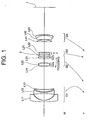
- Fig. 1 is a sectional view showing a lens configuration of a zoom lens system according to Example 1 of the present embodiment in a wide-angle end state.
- the zoom lens system according to Example 1 is composed of, in order from an object, a first lens group G1 having negative refractive power, a second lens group G2 having positive refractive power, a third lens group G3 having negative refractive power, and a fourth lens group G4 having positive refractive power.
- the first lens group G1 is composed of, in order from the object, a negative meniscus lens L11 having a convex surface facing the object, a double concave negative lens L12, and a positive meniscus lens L13 having a convex surface facing the object.
- the negative meniscus lens L11 is an aspherical lens in which an aspherical surface is formed on a resin layer disposed on the image side glass lens surface.
- the second lens group G2 is composed of, in order from the object, a cemented lens constructed by a negative meniscus lens L21 having a convex surface facing the object cemented with a double convex positive lens L22, and a positive meniscus lens L23 having a convex surface facing the object.
- the third lens group G3 is composed of a cemented lens constructed by, in order from the object, a positive meniscus lens L31 having a concave surface facing the object cemented with a double concave negative lens L32.
- the object side lens surface of the positive meniscus lens L31 is an aspherical surface.
- the fourth lens group G4 is composed of, in order from the object, a positive meniscus lens L41 having a concave surface facing the object, and a cemented lens constructed by a double convex positive lens L42 cemented with a negative meniscus lens L43 having a convex surface facing the image.
- the zoom lens system according to Example 1 upon zooming from a wide-angle end state to a telephoto end state, the first lens group G1 is moved at first to the image side and then to the object side, the second lens group G2, the third lens group G3, and the fourth lens group G4 are moved to the object such that a distance between the second lens group G2 and the third lens group G3 increases, and a distance between the third lens group G3 and the fourth lens group G4 decreases.
- An aperture stop S is disposed between the second lens group G2 and the third lens group G3, and moved together with the third lens group G3 upon zooming from the wide-angle end state to the telephoto end state.
- an image blur caused by a camera shake is corrected by shifting the third lens group G3 in a direction substantially perpendicular to the optical axis.
- the second lens group G2 is composed of, in order from the object, a front group G2a having positive refractive power, and a rear group G2b having positive refractive power. Focusing from infinity to a close object is carried out by moving the front group G2a along the optical axis.
- the left most column “i” shows the lens surface number counted in order from the object side
- the second column “r” shows a radius of curvature of the lens surface
- the third column “d” shows a distance to the next surface
- Bf denotes a back focal length.
- W denotes a wide-angle end state
- M denotes an intermediate focal length state
- T denotes a telephoto end state
- f denotes a focal length of the zoom lens system
- FNO denotes an f-number
- ⁇ denotes a half angle of view in degrees
- y denotes an image height
- TL denotes a total lens length
- Bf denotes a back focal length.
- di denotes a variable distance at the surface number i
- ⁇ denotes imaging magnification upon focusing on a close object
- d0 denotes a distance between the object and the most object side lens surface.
- mm is generally used for the unit of length such as the focal length, the radius of curvature and the distance to the next lens surface.
- the unit is not necessarily to be limited to "mm", and any other suitable unit can be used.
- the explanation of reference symbols is the same in the other Examples, so that duplicated explanations are omitted.
- a vibration reduction coefficient which is a ratio of a moving amount of an image on the image plane to that of the moving lens group perpendicularly to the optical axis upon correcting a camera shake, of K, in order to correct rotational camera shake of an angle ⁇
- the moving lens group for correcting the camera shake may be moved by the amount of (f ⁇ tan ⁇ )/K perpendicularly to the optical axis.
- the vibration reduction coefficient K is 1.097, and the focal length is 18.5(mm), so that the moving amount of the third lens group G3 for correcting a rotational camera shake of 0.7 degrees is 0.206(mm).
- the vibration reduction coefficient K is 1.897, and the focal length is 53.4(mm), so that the moving amount of the third lens group G3 for correcting a rotational camera shake of 0.4 degrees is 0.198(mm).
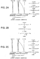
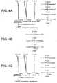
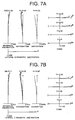
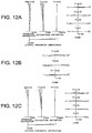
- FNO denotes an f-number
- Y denotes an image height
- NA denotes a numerical aperture.
- f-number with respect to the maximum aperture or the maximum numerical aperture is shown.
- astigmatism and distortion the maximum value of the image height is shown.
- coma coma with respect to each image height is shown.
- astigmatism a solid line indicates a sagittal image plane, and a broken line indicates a meridional image plane.
- the zoom lens system according to Example 1 shows superb optical performance as a result of good corrections to various aberrations in the wide-angle end state, in the intermediate focal length state, and in the telephoto end state.
- Fig. 5 is a sectional view showing a lens configuration of a zoom lens system according to Example 2 of the present embodiment in a wide-angle end state.
- the zoom lens system according to Example 2 is composed of, in order from an object, a first lens group G1 having negative refractive power, a second lens group G2 having positive refractive power, a third lens group G3 having negative refractive power, and a fourth lens group G4 having positive refractive power.
- the first lens group G1 is composed of, in order from the object, a negative meniscus lens L11 having a convex surface facing the object, a double concave negative lens L12, and a positive meniscus lens L13 having a convex surface facing the object.
- the negative meniscus lens L11 is an aspherical lens in which an aspherical surface is formed on a resin layer disposed on an image plane I side glass lens surface.
- the second lens group G2 is composed of, in order from the object, a cemented lens constructed by a negative meniscus lens L21 having a convex surface facing the object cemented with a double convex positive lens L22, and a double convex positive lens L23.
- the third lens group G3 is composed of a cemented lens constructed by, in order from the object, a positive meniscus lens L31 having a concave surface facing the object cemented with a double concave negative lens L32.
- the fourth lens group G4 is composed of, in order from the object, a positive meniscus lens L41 having a concave surface facing the object, and a cemented lens constructed by a double convex positive lens L42 cemented with a negative meniscus lens L43 having a convex surface facing the image.
- the zoom lens system according to Example 2 upon zooming from a wide-angle end state to a telephoto end state, the first lens group G1 is moved at first to the image side and then to the object side, the second lens group G2, the third lens group G3, and the fourth lens group G4 are moved to the object such that a distance between the second lens group G2 and the third lens group G3 increases, and a distance between the third lens group G3 and the fourth lens group G4 decreases.
- An aperture stop S is disposed between the second lens group G2 and the third lens group G3, and moved together with the third lens group G3 upon zooming from the wide-angle end state to the telephoto end state.
- an image blur caused by a camera shake is corrected by shifting the third lens group G3 in a direction substantially perpendicular to an optical axis.
- the second lens group G2 is composed of, in order from the object, a front group G2a having positive refractive power, and a rear group G2b having positive refractive power. Focusing from infinity to a close object is carried out by moving the front group G2a along the optical axis.
- the vibration reduction coefficient K is 1.080, and the focal length is 18.5(mm), so that the moving amount of the third lens group G3 for correcting a rotational camera shake of 0.7 degrees is 0.209(mm).
- the vibration reduction coefficient K is 1.914, and the focal length is 53.4(mm), so that the moving amount of the third lens group G3 for correcting a rotational camera shake of 0.4 degrees is 0.203(mm).
- the zoom lens system according to Example 2 shows superb optical performance as a result of good corrections to various aberrations in the wide-angle end state, in the intermediate focal length state, and in the telephoto end state.
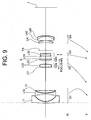
- Fig. 9 is a sectional view showing a lens configuration of a zoom lens system according to Example 3 of the present embodiment in a wide-angle end state.
- the zoom lens system according to Example 3 is composed of, in order from an object, a first lens group G1 having negative refractive power, a second lens group G2 having positive refractive power, a third lens group G3 having negative refractive power, and a fourth lens group G4 having positive refractive power.
- the first lens group G1 is composed of, in order from the object, a negative meniscus lens L11 having a convex surface facing the object, a double concave negative lens L12, and a positive meniscus lens L13 having a convex surface facing the object.
- the negative meniscus lens L11 is an aspherical lens in which an aspherical surface is formed on a resin layer disposed on an image plane I side glass lens surface.
- the second lens group G2 is composed of, in order from the object, a cemented lens constructed by a negative meniscus lens L21 having a convex surface facing the object cemented with a double convex positive lens L22, and a positive meniscus lens L23 having a convex surface facing the object.
- the third lens group G3 is composed of a cemented lens constructed by, in order from the object, a positive meniscus lens L31 having a concave surface facing the object cemented with a double concave negative lens L32.
- the fourth lens group G4 is composed of, in order from the object, a positive meniscus lens L41 having a concave surface facing the object, and a cemented lens constructed by a double convex positive lens L42 cemented with a negative meniscus lens L43 having a convex surface facing the image.
- the zoom lens system according to Example 3 upon zooming from a wide-angle end state to a telephoto end state, the first lens group G1 is moved at first to the image side and then to the object side, the second lens group G2, the third lens group G3, and the fourth lens group G4 are moved to the object such that a distance between the second lens group G2 and the third lens group G3 increases, and a distance between the third lens group G3 and the fourth lens group G4 decreases.
- An aperture stop S is disposed between the second lens group G2 and the third lens group G3, and moved together with the third lens group G3 upon zooming from the wide-angle end state to the telephoto end state.
- an image blur caused by a camera shake is corrected by shifting the third lens group G3 in a direction substantially perpendicular to an optical axis.
- a flare stopper FS is disposed in the vicinity of the third lens group and moved in a body with the third lens group.
- the second lens group G2 is composed of, in order from the object, a front group G2a having positive refractive power, and a rear group G2b having positive refractive power. Focusing from infinity to a close object is carried out by moving the front group G2a along the optical axis.
- the vibration reduction coefficient K is 1.143, and the focal length is 18.5(mm), so that the moving amount of the third lens group G3 for correcting a rotational camera shake of 0.7 degrees is 0.198(mm).
- the vibration reduction coefficient K is 1.929, and the focal length is 53.4(mm), so that the moving amount of the third lens group G3 for correcting a rotational camera shake of 0.4 degrees is 0.193(mm).
- the zoom lens system according to Example 3 shows superb optical performance as a result of good corrections to various aberrations in the wide-angle end state, in the intermediate focal length state, and in the telephoto end state.
- each Example makes it possible to provide a zoom lens system having a high zoom ratio and high optical performance with a vibration reduction function, suitable for a film camera, an electronic still camera, a video camera, and the like.
- Fig. 13 is a schematic diagram showing a camera equipped with the zoom lens system according to Example 1 of the present embodiment.
- the camera 1 is a single-lens reflex digital camera equipped with the zoom lens system according to Example 1 as an image-taking lens 2.
- the zoom lens system according to Example 1 is used as an image-taking lens 2.
- the camera 1 In the camera 1, light emitted from an object (not shown) is converged by an image-taking lens 2, and focused on a focusing screen 4 through a quick return mirror 3. The object image focused on the focusing screen 4 is reflected a plurality of times by a pentagonal roof prism 5, and led to an eyepiece 6. Therefore, a photographer can observe the object image as an erected image through the eyepiece 6.
- the quick return mirror 3 is removed from an optical path, and the light from the object (not shown) reaches an imaging device 7. Accordingly, light from the object is captured by the imaging device 7 and stored in a memory (not shown) as an object image. In this manner, the photographer can take a picture of the object by the camera 1.
- the zoom lens system according to Example 1 of the present embodiment attached to the camera 1 as an image-taking lens 2 makes it possible to realize a vibration reduction function, a high zoom ratio, and high optical performance by means of the specific lens configuration. Accordingly, the camera 1 makes it possible to realize a vibration reduction function, a high zoom ratio, and high optical performance.
- zoom lens system with a four-lens-group configuration is shown as each Example of the present embodiment, the present embodiment can be applied to other lens-group configurations such as a five-lens-group configuration, and a six-lens-group configuration.
- a portion of a lens group, a single lens group, or a plurality of lens groups may be moved along the optical axis.
- the focusing lens group(s) may be used for auto focus, and suitable for being driven by a motor such as an ultrasonic motor. In a zoom lens system according to the present embodiment, it is preferable that a portion of the second lens group is used for the focusing lens group.
- a lens group or a portion of a lens group may be sifted in a direction perpendicular to the optical axis as a vibration reduction lens group for correcting an image blur caused by a camera shake. It is particularly preferable that the second lens group or the third lens group is used as a vibration reduction lens group.
- any lens surface may be an aspherical surface.
- the aspherical surface may be fabricated by a fine grinding process, a glass molding process that a glass material is formed into an aspherical shape by a mold, or a compound type process that a resin material is formed into an aspherical shape on a glass surface.
- an aperture stop is preferably disposed in the vicinity of the third lens group, the function may be substituted by a lens frame without disposing a member as an aperture stop.
- An antireflection coating having high transmittance over a broad wavelength range may be applied to each lens surface to reduce flare or ghost images, so that high optical performance with a high contrast can be attained.
Landscapes
- Physics & Mathematics (AREA)
- General Physics & Mathematics (AREA)
- Optics & Photonics (AREA)
- Nonlinear Science (AREA)
- Lenses (AREA)
- Adjustment Of Camera Lenses (AREA)
Claims (18)
- Système à lentilles de zoom comprenant, dans l'ordre à partir d'un côté objet :un premier groupe de lentilles (G1) qui présente un pouvoir de réfraction négatif ;un deuxième groupe de lentilles (G2) qui présente un pouvoir de réfraction positif ; etun troisième groupe de lentilles (G3) qui présente un pouvoir de réfraction négatif ;chaque distance entre des groupes de lentilles adjacents étant variable de façon à zoomer à partir d'un état final de grand-angle (W) jusqu'à un état final de téléobjectif (T) ;le deuxième groupe de lentilles (G2) comprenant, dans l'ordre à partir du côté objet, un groupe avant (G2a) qui présente un pouvoir de réfraction positif, et un groupe arrière (G2b),le groupe avant (G2a) du deuxième groupe de lentilles étant mobile le long de l'axe optique du système à lentilles de zoom et une distance entre le groupe avant et le groupe arrière étant variable pour la focalisation sur l'objet, etl'expression conditionnelle suivante étant satisfaite :
 caractérisé en ce que :en outre, l'expression conditionnelle suivante est satisfaite :
- Système à lentilles de zoom selon la revendication 1, comprenant en outre un quatrième groupe de lentilles (G4) qui présente un pouvoir de réfraction positif, dans lequel lors d'un zoom à partir de l'état final de grand-angle jusqu'à l'état final de téléobjectif, une distance entre le deuxième groupe de lentilles (G2) et le troisième groupe de lentilles (G3) augmente, et une distance entre le troisième groupe de lentilles (G3) et le quatrième groupe de lentilles (G4) diminue.
- Système à lentilles de zoom selon la revendication 2, dans lequel le quatrième groupe de lentilles (G4) comprend une lentille collée.
- Système à lentilles de zoom selon la revendication 2, dans lequel le quatrième groupe de lentilles (G4) est constitué, dans l'ordre à partir d'un côté image, d'une lentille collée obtenue à l'aide d'une lentille négative (L43) collée avec une lentille positive (L42), et d'une simple lentille (L41) qui présente un pouvoir de réfraction positif.
- Système à lentilles de zoom selon l'une des revendications précédentes, dans lequel le troisième groupe de lentilles (G3) peut être décalé dans une direction sensiblement perpendiculaire à l'axe optique.
- Système à lentilles de zoom selon l'une des revendications précédentes, dans lequel au moins une partie du troisième groupe de lentilles (G3) peut être décalée dans une direction sensiblement perpendiculaire à l'axe optique.
- Système à lentilles de zoom selon l'une des revendications précédentes, dans lequel au moins une partie du deuxième groupe de lentilles (G2) peut être décalée dans une direction sensiblement perpendiculaire à l'axe optique.
- Système à lentilles de zoom selon l'une des revendications précédentes, comprenant en outre une butée d'ouverture (S), la butée d'ouverture étant mobile avec le troisième groupe de lentilles (G3) pour zoomer à partir de l'état final de grand-angle jusqu'à l'état final de téléobjectif (T).
- Système à lentilles de zoom selon l'une des revendications précédentes, dans lequel le troisième groupe de lentilles (G3) comprend au moins une lentille collée.
- Système à lentilles de zoom selon l'une des revendications précédentes, dans lequel le deuxième groupe de lentilles (G2) comprend au moins une lentille collée.
- Système à lentilles de zoom selon l'une des revendications précédentes, dans lequel le groupe avant (G2a) du deuxième groupe de lentilles (G2) est constitué uniquement d'une lentille collée.
- Système à lentilles de zoom selon l'une des revendications précédentes, dans lequel le premier groupe de lentilles (G1) est mobile d'abord d'un côté d'image puis vers le côté objet pour zoomer à partir de l'état final de grand-angle (W) vers l'état final de téléobjectif (T).
- Système à lentilles de zoom selon l'une des revendications précédentes, dans lequel l'expression conditionnelle suivante est satisfaite :

- Système à lentilles de zoom selon l'une des revendications précédentes, dans lequel la surface de lentille du système à lentilles de zoom la plus proche du côté image est une surface convexe qui fait face à l'image.
- Appareil optique équipé du système à lentilles de zoom selon la revendication 1.
- Procédé destiné à faire varier la focale d'un système à lentilles de zoom comprenant les étapes suivantes :fournir le système à lentilles de zoom comprenant, dans l'ordre à partir d'un côté objet, un premier groupe de lentilles (G1) qui présente un pouvoir de réfraction négatif, un deuxième groupe de lentilles (G2) qui présente un pouvoir de réfraction positif, et un troisième groupe de lentilles (G3) qui présente un pouvoir de réfraction négatif, le deuxième groupe de lentilles (G2) comprenant, dans l'ordre à partir du côté objet, un groupe avant (G2a) qui présente un pouvoir de réfraction positif et un groupe arrière (G2b), le groupe avant étant déplacé le long d'un axe optique du système à lentilles de zoom et une distance entre le groupe avant et le groupe arrière étant variable pour la focalisation sur l'objet et l'expression conditionnelle suivante étant satisfaite :
 faire varier chaque distance entre des groupes de lentilles adjacents lors d'un zoom à partir d'un état final de grand-angle (W) jusqu'à un état final de téléobjectif ;caractérisé en ce que :en outre, l'expression conditionnelle suivante est satisfaite :
- Procédé selon la revendication 16, comprenant en outre l'étape suivante :décalage d'au moins une portion du troisième groupe de lentilles (G3) dans une direction sensiblement perpendiculaire à l'axe optique.
- Procédé selon la revendication 16, dans lequel le système à lentilles de zoom est réalisé selon l'une des revendications 9, 10, 11, 13 ou 14.
Priority Applications (1)
| Application Number | Priority Date | Filing Date | Title |
|---|---|---|---|
| EP11180960.4A EP2397881B1 (fr) | 2007-06-29 | 2008-06-25 | Zoom optique de type rétrofocus avec quatre groupes de lentilles |
Applications Claiming Priority (1)
| Application Number | Priority Date | Filing Date | Title |
|---|---|---|---|
| JP2007173146A JP5407119B2 (ja) | 2007-06-29 | 2007-06-29 | 変倍光学系、光学装置、変倍光学系の変倍方法 |
Related Child Applications (2)
| Application Number | Title | Priority Date | Filing Date |
|---|---|---|---|
| EP11180960.4A Division EP2397881B1 (fr) | 2007-06-29 | 2008-06-25 | Zoom optique de type rétrofocus avec quatre groupes de lentilles |
| EP11180960.4A Division-Into EP2397881B1 (fr) | 2007-06-29 | 2008-06-25 | Zoom optique de type rétrofocus avec quatre groupes de lentilles |
Publications (3)
| Publication Number | Publication Date |
|---|---|
| EP2009478A2 EP2009478A2 (fr) | 2008-12-31 |
| EP2009478A3 EP2009478A3 (fr) | 2009-02-18 |
| EP2009478B1 true EP2009478B1 (fr) | 2016-08-10 |
Family
ID=39718951
Family Applications (2)
| Application Number | Title | Priority Date | Filing Date |
|---|---|---|---|
| EP08252182.4A Not-in-force EP2009478B1 (fr) | 2007-06-29 | 2008-06-25 | Zoom optique de type rétrofocus avec quatre groupes de lentilles |
| EP11180960.4A Not-in-force EP2397881B1 (fr) | 2007-06-29 | 2008-06-25 | Zoom optique de type rétrofocus avec quatre groupes de lentilles |
Family Applications After (1)
| Application Number | Title | Priority Date | Filing Date |
|---|---|---|---|
| EP11180960.4A Not-in-force EP2397881B1 (fr) | 2007-06-29 | 2008-06-25 | Zoom optique de type rétrofocus avec quatre groupes de lentilles |
Country Status (4)
| Country | Link |
|---|---|
| US (1) | US7961409B2 (fr) |
| EP (2) | EP2009478B1 (fr) |
| JP (1) | JP5407119B2 (fr) |
| CN (1) | CN101334519B (fr) |
Families Citing this family (25)
| Publication number | Priority date | Publication date | Assignee | Title |
|---|---|---|---|---|
| WO2008010563A1 (fr) | 2006-07-21 | 2008-01-24 | Nikon Corporation | Système optique à puissance variable, dispositif d'imagerie, procédé d'agrandissement variable d'un système optique à puissance variable |
| JP5078498B2 (ja) * | 2007-08-09 | 2012-11-21 | キヤノン株式会社 | ズームレンズ及びそれを有する撮像装置 |
| JP2009251117A (ja) * | 2008-04-02 | 2009-10-29 | Panasonic Corp | ズームレンズ系、交換レンズ装置、及びカメラシステム |
| US8169718B2 (en) * | 2009-04-13 | 2012-05-01 | Tamron Co., Ltd. | Wide-angle zoom lens |
| US8934176B2 (en) * | 2009-11-13 | 2015-01-13 | Nikon Corporation | Optical system, optical apparatus and method for manufacturing optical system |
| JP5609072B2 (ja) * | 2009-11-13 | 2014-10-22 | 株式会社ニコン | レンズ系、光学機器、レンズ系の製造方法 |
| JP5651942B2 (ja) * | 2009-11-24 | 2015-01-14 | 株式会社ニコン | 撮影レンズ、光学装置、撮影レンズの調整方法 |
| JP5807166B2 (ja) | 2010-07-12 | 2015-11-10 | パナソニックIpマネジメント株式会社 | ズームレンズ系、交換レンズ装置及びカメラシステム |
| US9097881B2 (en) * | 2010-07-26 | 2015-08-04 | Nikon Corporation | Zoom lens system, optical apparatus and method for manufacturing zoom lens system |
| JP5500382B2 (ja) * | 2010-09-22 | 2014-05-21 | 株式会社ニコン | 撮影レンズ、この撮影レンズを有する光学機器、及び、撮影レンズの製造方法 |
| WO2012086153A1 (fr) * | 2010-12-22 | 2012-06-28 | パナソニック株式会社 | Système d'objectif à focale variable, dispositif à objectif interchangeable, et système d'appareil photographique |
| WO2012086154A1 (fr) * | 2010-12-22 | 2012-06-28 | パナソニック株式会社 | Système d'objectif à focale variable, dispositif à objectif interchangeable, et système d'appareil photographique |
| KR101950999B1 (ko) | 2012-03-09 | 2019-02-21 | 삼성전자주식회사 | 줌 렌즈 및 이를 포함한 촬영 장치 |
| JP6251947B2 (ja) * | 2012-08-30 | 2017-12-27 | 株式会社ニコン | 変倍光学系、この変倍光学系を有する光学装置、及び、変倍光学系の製造方法 |
| US9250425B2 (en) * | 2012-12-04 | 2016-02-02 | Samsung Electronics Co., Ltd. | Zoom lens and electronic device including the same |
| JP6152641B2 (ja) | 2012-12-26 | 2017-06-28 | リコーイメージング株式会社 | ズームレンズ系及びこれを備えた電子撮像装置 |
| CN109188663B (zh) * | 2013-06-28 | 2021-10-15 | 株式会社尼康 | 变倍光学系统、光学设备和该变倍光学系统的制造方法 |
| WO2016121903A1 (fr) * | 2015-01-30 | 2016-08-04 | 株式会社ニコン | Système optique à grossissement variable, instrument optique, et procédé de fabrication d'un système optique à grossissement variable |
| JP6524703B2 (ja) * | 2015-02-26 | 2019-06-05 | 株式会社ニコン | ズームレンズ、光学機器及びズームレンズの製造方法 |
| JP2018010219A (ja) | 2016-07-15 | 2018-01-18 | 株式会社ニコン | 変倍光学系、光学機器及び変倍光学系の製造方法 |
| CN107065406A (zh) * | 2017-03-21 | 2017-08-18 | 北京和光科技有限公司 | 一种通用型短焦投影光学系统 |
| WO2018185868A1 (fr) * | 2017-04-05 | 2018-10-11 | 株式会社ニコン | Système optique à grossissement variable, dispositif optique, et procédé de production d'un système optique à grossissement variable |
| CN112213846B (zh) * | 2019-07-09 | 2022-08-02 | Oppo广东移动通信有限公司 | 变焦镜头和电子装置 |
| CN116794797A (zh) * | 2022-03-14 | 2023-09-22 | 信泰光学(深圳)有限公司 | 光学系统 |
| CN119758571A (zh) * | 2025-01-21 | 2025-04-04 | 维沃移动通信有限公司 | 光学系统、摄像头模组和电子设备 |
Family Cites Families (17)
| Publication number | Priority date | Publication date | Assignee | Title |
|---|---|---|---|---|
| JP2629904B2 (ja) | 1988-11-18 | 1997-07-16 | キヤノン株式会社 | リヤーフォーカス式のズームレンズ |
| JPH05173071A (ja) * | 1991-12-25 | 1993-07-13 | Nikon Corp | 広角ズームレンズ |
| JPH07152002A (ja) * | 1993-11-29 | 1995-06-16 | Nikon Corp | 防振機能を備えたズームレンズ |
| JPH1039210A (ja) * | 1996-07-24 | 1998-02-13 | Nikon Corp | ズームレンズ |
| JPH11174329A (ja) * | 1997-12-15 | 1999-07-02 | Canon Inc | 防振機能を有した変倍光学系 |
| JP4285951B2 (ja) * | 2002-08-02 | 2009-06-24 | オリンパス株式会社 | ズームレンズ及びそれを用いた電子撮像装置 |
| JP4360086B2 (ja) * | 2002-12-27 | 2009-11-11 | 株式会社ニコン | ズームレンズ |
| JP2004348082A (ja) * | 2003-05-26 | 2004-12-09 | Olympus Corp | 光路折り曲げ光学系 |
| JP4720117B2 (ja) * | 2003-07-17 | 2011-07-13 | 株式会社ニコン | ズームレンズ |
| JP4289958B2 (ja) * | 2003-09-19 | 2009-07-01 | キヤノン株式会社 | ズームレンズ及びそれを有する撮像装置 |
| JP4507543B2 (ja) * | 2003-09-29 | 2010-07-21 | 株式会社ニコン | ズームレンズ |
| JP4681842B2 (ja) | 2004-09-30 | 2011-05-11 | キヤノン株式会社 | ズームレンズ及びそれを有する撮像装置 |
| JP4834360B2 (ja) * | 2005-09-12 | 2011-12-14 | キヤノン株式会社 | ズームレンズ及びそれを有する撮像装置 |
| JP4876510B2 (ja) * | 2005-09-28 | 2012-02-15 | 株式会社ニコン | ズームレンズ |
| JP4821237B2 (ja) * | 2005-09-29 | 2011-11-24 | 株式会社ニコン | ズームレンズ |
| JP4422098B2 (ja) | 2005-12-26 | 2010-02-24 | 義夫 小西 | 光を放出する柱 |
| WO2008010563A1 (fr) | 2006-07-21 | 2008-01-24 | Nikon Corporation | Système optique à puissance variable, dispositif d'imagerie, procédé d'agrandissement variable d'un système optique à puissance variable |
-
2007
- 2007-06-29 JP JP2007173146A patent/JP5407119B2/ja not_active Expired - Fee Related
-
2008
- 2008-06-14 US US12/139,464 patent/US7961409B2/en active Active
- 2008-06-25 EP EP08252182.4A patent/EP2009478B1/fr not_active Not-in-force
- 2008-06-25 EP EP11180960.4A patent/EP2397881B1/fr not_active Not-in-force
- 2008-06-30 CN CN2008101295512A patent/CN101334519B/zh active Active
Also Published As
| Publication number | Publication date |
|---|---|
| US20090002841A1 (en) | 2009-01-01 |
| CN101334519A (zh) | 2008-12-31 |
| EP2397881A1 (fr) | 2011-12-21 |
| EP2009478A2 (fr) | 2008-12-31 |
| EP2009478A3 (fr) | 2009-02-18 |
| JP5407119B2 (ja) | 2014-02-05 |
| CN101334519B (zh) | 2012-03-21 |
| EP2397881B1 (fr) | 2014-05-14 |
| JP2009014761A (ja) | 2009-01-22 |
| US7961409B2 (en) | 2011-06-14 |
Similar Documents
| Publication | Publication Date | Title |
|---|---|---|
| EP2397881B1 (fr) | Zoom optique de type rétrofocus avec quatre groupes de lentilles | |
| EP2620796B1 (fr) | Système optique et appareil d'imagerie | |
| EP2360504B1 (fr) | Système de lentilles de zoom, appareil optique et procédé de fabrication de lentilles de zoom | |
| EP2362259B1 (fr) | Objectif macro du type téléobjectif ayant trois groupes de lentilles et focalisation avant, et son procédé de fabrication | |
| EP1881357B1 (fr) | Zoom téléphoto anti-vibrations avec quatre groupes de lentilles | |
| US8144403B2 (en) | Zoom lens system, optical apparatus, and method for zooming | |
| US7551367B2 (en) | Wide-angle lens, optical apparatus and method for focusing | |
| US10437026B2 (en) | Zoom lens system, imaging apparatus, and method for zooming the zoom lens system | |
| EP1998204B1 (fr) | Zoom téléphoto anti-vibrations avec quatre groupes de lentilles et à focalisation avec le groupe de lentilles arrière | |
| EP1868022B1 (fr) | Zoom optique avec trois groupes de lentilles, le premier étant négatif | |
| EP1870760A1 (fr) | Zoom de type rétrofocus à quatre groupes de lentilles | |
| EP3252519B1 (fr) | Objectif à focale variable, appareil optique, et procédé de fabrication d'un objectif à focale variable | |
| JP7821409B2 (ja) | 変倍光学系及び光学機器 | |
| EP2020613A2 (fr) | Système optique | |
| JP5622103B2 (ja) | ズームレンズ、このズームレンズを搭載した光学機器、及び、ズームレンズの製造方法 | |
| US9140882B2 (en) | Zoom lens, optical apparatus, and method for manufacturing the zoom lens | |
| JP2007108544A (ja) | ズームレンズ及びそれを有する撮像装置 | |
| JP5505770B2 (ja) | ズームレンズ、光学機器 | |
| JP6205857B2 (ja) | 変倍光学系、撮像装置、および変倍光学系の製造方法 |
Legal Events
| Date | Code | Title | Description |
|---|---|---|---|
| PUAI | Public reference made under article 153(3) epc to a published international application that has entered the european phase |
Free format text: ORIGINAL CODE: 0009012 |
|
| AK | Designated contracting states |
Kind code of ref document: A2 Designated state(s): AT BE BG CH CY CZ DE DK EE ES FI FR GB GR HR HU IE IS IT LI LT LU LV MC MT NL NO PL PT RO SE SI SK TR |
|
| AX | Request for extension of the european patent |
Extension state: AL BA MK RS |
|
| PUAL | Search report despatched |
Free format text: ORIGINAL CODE: 0009013 |
|
| AK | Designated contracting states |
Kind code of ref document: A3 Designated state(s): AT BE BG CH CY CZ DE DK EE ES FI FR GB GR HR HU IE IS IT LI LT LU LV MC MT NL NO PL PT RO SE SI SK TR |
|
| AX | Request for extension of the european patent |
Extension state: AL BA MK RS |
|
| 17P | Request for examination filed |
Effective date: 20090807 |
|
| 17Q | First examination report despatched |
Effective date: 20090903 |
|
| AKX | Designation fees paid |
Designated state(s): AT BE BG CH CY CZ DE DK EE ES FI FR GB GR HR HU IE IS IT LI LT LU LV MC MT NL NO PL PT RO SE SI SK TR |
|
| RAP1 | Party data changed (applicant data changed or rights of an application transferred) |
Owner name: NIKON CORPORATION |
|
| RAP1 | Party data changed (applicant data changed or rights of an application transferred) |
Owner name: NIKON CORPORATION |
|
| GRAP | Despatch of communication of intention to grant a patent |
Free format text: ORIGINAL CODE: EPIDOSNIGR1 |
|
| INTG | Intention to grant announced |
Effective date: 20160223 |
|
| GRAS | Grant fee paid |
Free format text: ORIGINAL CODE: EPIDOSNIGR3 |
|
| GRAA | (expected) grant |
Free format text: ORIGINAL CODE: 0009210 |
|
| AK | Designated contracting states |
Kind code of ref document: B1 Designated state(s): AT BE BG CH CY CZ DE DK EE ES FI FR GB GR HR HU IE IS IT LI LT LU LV MC MT NL NO PL PT RO SE SI SK TR |
|
| REG | Reference to a national code |
Ref country code: GB Ref legal event code: FG4D |
|
| REG | Reference to a national code |
Ref country code: CH Ref legal event code: EP Ref country code: AT Ref legal event code: REF Ref document number: 819567 Country of ref document: AT Kind code of ref document: T Effective date: 20160815 |
|
| REG | Reference to a national code |
Ref country code: IE Ref legal event code: FG4D |
|
| REG | Reference to a national code |
Ref country code: DE Ref legal event code: R096 Ref document number: 602008045515 Country of ref document: DE |
|
| REG | Reference to a national code |
Ref country code: LT Ref legal event code: MG4D |
|
| REG | Reference to a national code |
Ref country code: NL Ref legal event code: MP Effective date: 20160810 |
|
| REG | Reference to a national code |
Ref country code: AT Ref legal event code: MK05 Ref document number: 819567 Country of ref document: AT Kind code of ref document: T Effective date: 20160810 |
|
| PG25 | Lapsed in a contracting state [announced via postgrant information from national office to epo] |
Ref country code: NL Free format text: LAPSE BECAUSE OF FAILURE TO SUBMIT A TRANSLATION OF THE DESCRIPTION OR TO PAY THE FEE WITHIN THE PRESCRIBED TIME-LIMIT Effective date: 20160810 Ref country code: HR Free format text: LAPSE BECAUSE OF FAILURE TO SUBMIT A TRANSLATION OF THE DESCRIPTION OR TO PAY THE FEE WITHIN THE PRESCRIBED TIME-LIMIT Effective date: 20160810 Ref country code: IT Free format text: LAPSE BECAUSE OF FAILURE TO SUBMIT A TRANSLATION OF THE DESCRIPTION OR TO PAY THE FEE WITHIN THE PRESCRIBED TIME-LIMIT Effective date: 20160810 Ref country code: LT Free format text: LAPSE BECAUSE OF FAILURE TO SUBMIT A TRANSLATION OF THE DESCRIPTION OR TO PAY THE FEE WITHIN THE PRESCRIBED TIME-LIMIT Effective date: 20160810 Ref country code: FI Free format text: LAPSE BECAUSE OF FAILURE TO SUBMIT A TRANSLATION OF THE DESCRIPTION OR TO PAY THE FEE WITHIN THE PRESCRIBED TIME-LIMIT Effective date: 20160810 Ref country code: NO Free format text: LAPSE BECAUSE OF FAILURE TO SUBMIT A TRANSLATION OF THE DESCRIPTION OR TO PAY THE FEE WITHIN THE PRESCRIBED TIME-LIMIT Effective date: 20161110 Ref country code: IS Free format text: LAPSE BECAUSE OF FAILURE TO SUBMIT A TRANSLATION OF THE DESCRIPTION OR TO PAY THE FEE WITHIN THE PRESCRIBED TIME-LIMIT Effective date: 20161210 |
|
| PG25 | Lapsed in a contracting state [announced via postgrant information from national office to epo] |
Ref country code: LV Free format text: LAPSE BECAUSE OF FAILURE TO SUBMIT A TRANSLATION OF THE DESCRIPTION OR TO PAY THE FEE WITHIN THE PRESCRIBED TIME-LIMIT Effective date: 20160810 Ref country code: GR Free format text: LAPSE BECAUSE OF FAILURE TO SUBMIT A TRANSLATION OF THE DESCRIPTION OR TO PAY THE FEE WITHIN THE PRESCRIBED TIME-LIMIT Effective date: 20161111 Ref country code: SE Free format text: LAPSE BECAUSE OF FAILURE TO SUBMIT A TRANSLATION OF THE DESCRIPTION OR TO PAY THE FEE WITHIN THE PRESCRIBED TIME-LIMIT Effective date: 20160810 Ref country code: PT Free format text: LAPSE BECAUSE OF FAILURE TO SUBMIT A TRANSLATION OF THE DESCRIPTION OR TO PAY THE FEE WITHIN THE PRESCRIBED TIME-LIMIT Effective date: 20161212 Ref country code: ES Free format text: LAPSE BECAUSE OF FAILURE TO SUBMIT A TRANSLATION OF THE DESCRIPTION OR TO PAY THE FEE WITHIN THE PRESCRIBED TIME-LIMIT Effective date: 20160810 Ref country code: AT Free format text: LAPSE BECAUSE OF FAILURE TO SUBMIT A TRANSLATION OF THE DESCRIPTION OR TO PAY THE FEE WITHIN THE PRESCRIBED TIME-LIMIT Effective date: 20160810 Ref country code: PL Free format text: LAPSE BECAUSE OF FAILURE TO SUBMIT A TRANSLATION OF THE DESCRIPTION OR TO PAY THE FEE WITHIN THE PRESCRIBED TIME-LIMIT Effective date: 20160810 |
|
| PG25 | Lapsed in a contracting state [announced via postgrant information from national office to epo] |
Ref country code: RO Free format text: LAPSE BECAUSE OF FAILURE TO SUBMIT A TRANSLATION OF THE DESCRIPTION OR TO PAY THE FEE WITHIN THE PRESCRIBED TIME-LIMIT Effective date: 20160810 Ref country code: EE Free format text: LAPSE BECAUSE OF FAILURE TO SUBMIT A TRANSLATION OF THE DESCRIPTION OR TO PAY THE FEE WITHIN THE PRESCRIBED TIME-LIMIT Effective date: 20160810 |
|
| REG | Reference to a national code |
Ref country code: FR Ref legal event code: PLFP Year of fee payment: 10 Ref country code: DE Ref legal event code: R097 Ref document number: 602008045515 Country of ref document: DE |
|
| PG25 | Lapsed in a contracting state [announced via postgrant information from national office to epo] |
Ref country code: DK Free format text: LAPSE BECAUSE OF FAILURE TO SUBMIT A TRANSLATION OF THE DESCRIPTION OR TO PAY THE FEE WITHIN THE PRESCRIBED TIME-LIMIT Effective date: 20160810 Ref country code: SK Free format text: LAPSE BECAUSE OF FAILURE TO SUBMIT A TRANSLATION OF THE DESCRIPTION OR TO PAY THE FEE WITHIN THE PRESCRIBED TIME-LIMIT Effective date: 20160810 Ref country code: BE Free format text: LAPSE BECAUSE OF FAILURE TO SUBMIT A TRANSLATION OF THE DESCRIPTION OR TO PAY THE FEE WITHIN THE PRESCRIBED TIME-LIMIT Effective date: 20160810 Ref country code: BG Free format text: LAPSE BECAUSE OF FAILURE TO SUBMIT A TRANSLATION OF THE DESCRIPTION OR TO PAY THE FEE WITHIN THE PRESCRIBED TIME-LIMIT Effective date: 20161110 Ref country code: CZ Free format text: LAPSE BECAUSE OF FAILURE TO SUBMIT A TRANSLATION OF THE DESCRIPTION OR TO PAY THE FEE WITHIN THE PRESCRIBED TIME-LIMIT Effective date: 20160810 |
|
| PLBE | No opposition filed within time limit |
Free format text: ORIGINAL CODE: 0009261 |
|
| STAA | Information on the status of an ep patent application or granted ep patent |
Free format text: STATUS: NO OPPOSITION FILED WITHIN TIME LIMIT |
|
| 26N | No opposition filed |
Effective date: 20170511 |
|
| PG25 | Lapsed in a contracting state [announced via postgrant information from national office to epo] |
Ref country code: SI Free format text: LAPSE BECAUSE OF FAILURE TO SUBMIT A TRANSLATION OF THE DESCRIPTION OR TO PAY THE FEE WITHIN THE PRESCRIBED TIME-LIMIT Effective date: 20160810 |
|
| PG25 | Lapsed in a contracting state [announced via postgrant information from national office to epo] |
Ref country code: MC Free format text: LAPSE BECAUSE OF FAILURE TO SUBMIT A TRANSLATION OF THE DESCRIPTION OR TO PAY THE FEE WITHIN THE PRESCRIBED TIME-LIMIT Effective date: 20160810 |
|
| REG | Reference to a national code |
Ref country code: CH Ref legal event code: PL |
|
| REG | Reference to a national code |
Ref country code: IE Ref legal event code: MM4A |
|
| PG25 | Lapsed in a contracting state [announced via postgrant information from national office to epo] |
Ref country code: IE Free format text: LAPSE BECAUSE OF NON-PAYMENT OF DUE FEES Effective date: 20170625 Ref country code: LU Free format text: LAPSE BECAUSE OF NON-PAYMENT OF DUE FEES Effective date: 20170625 Ref country code: LI Free format text: LAPSE BECAUSE OF NON-PAYMENT OF DUE FEES Effective date: 20170630 Ref country code: CH Free format text: LAPSE BECAUSE OF NON-PAYMENT OF DUE FEES Effective date: 20170630 |
|
| REG | Reference to a national code |
Ref country code: FR Ref legal event code: PLFP Year of fee payment: 11 |
|
| PG25 | Lapsed in a contracting state [announced via postgrant information from national office to epo] |
Ref country code: MT Free format text: LAPSE BECAUSE OF NON-PAYMENT OF DUE FEES Effective date: 20170625 |
|
| PG25 | Lapsed in a contracting state [announced via postgrant information from national office to epo] |
Ref country code: HU Free format text: LAPSE BECAUSE OF FAILURE TO SUBMIT A TRANSLATION OF THE DESCRIPTION OR TO PAY THE FEE WITHIN THE PRESCRIBED TIME-LIMIT; INVALID AB INITIO Effective date: 20080625 |
|
| PG25 | Lapsed in a contracting state [announced via postgrant information from national office to epo] |
Ref country code: CY Free format text: LAPSE BECAUSE OF NON-PAYMENT OF DUE FEES Effective date: 20160810 |
|
| PG25 | Lapsed in a contracting state [announced via postgrant information from national office to epo] |
Ref country code: TR Free format text: LAPSE BECAUSE OF FAILURE TO SUBMIT A TRANSLATION OF THE DESCRIPTION OR TO PAY THE FEE WITHIN THE PRESCRIBED TIME-LIMIT Effective date: 20160810 |
|
| PGFP | Annual fee paid to national office [announced via postgrant information from national office to epo] |
Ref country code: FR Payment date: 20200512 Year of fee payment: 13 Ref country code: DE Payment date: 20200609 Year of fee payment: 13 |
|
| PGFP | Annual fee paid to national office [announced via postgrant information from national office to epo] |
Ref country code: GB Payment date: 20200618 Year of fee payment: 13 |
|
| REG | Reference to a national code |
Ref country code: DE Ref legal event code: R119 Ref document number: 602008045515 Country of ref document: DE |
|
| GBPC | Gb: european patent ceased through non-payment of renewal fee |
Effective date: 20210625 |
|
| PG25 | Lapsed in a contracting state [announced via postgrant information from national office to epo] |
Ref country code: GB Free format text: LAPSE BECAUSE OF NON-PAYMENT OF DUE FEES Effective date: 20210625 Ref country code: DE Free format text: LAPSE BECAUSE OF NON-PAYMENT OF DUE FEES Effective date: 20220101 |
|
| PG25 | Lapsed in a contracting state [announced via postgrant information from national office to epo] |
Ref country code: FR Free format text: LAPSE BECAUSE OF NON-PAYMENT OF DUE FEES Effective date: 20210630 |