EP2009521A1 - Verfahren zur Steuerung von Vorrichtungen zur motorisierten Schattierung und Steuerungssystem - Google Patents
Verfahren zur Steuerung von Vorrichtungen zur motorisierten Schattierung und Steuerungssystem Download PDFInfo
- Publication number
- EP2009521A1 EP2009521A1 EP07012807A EP07012807A EP2009521A1 EP 2009521 A1 EP2009521 A1 EP 2009521A1 EP 07012807 A EP07012807 A EP 07012807A EP 07012807 A EP07012807 A EP 07012807A EP 2009521 A1 EP2009521 A1 EP 2009521A1
- Authority
- EP
- European Patent Office
- Prior art keywords
- façade
- radiation
- control system
- thres
- anticip
- Prior art date
- Legal status (The legal status is an assumption and is not a legal conclusion. Google has not performed a legal analysis and makes no representation as to the accuracy of the status listed.)
- Withdrawn
Links
- 238000000034 method Methods 0.000 title claims abstract description 33
- 230000005855 radiation Effects 0.000 claims abstract description 192
- 238000001816 cooling Methods 0.000 claims abstract description 13
- 230000008034 disappearance Effects 0.000 claims description 18
- 125000000205 L-threonino group Chemical group [H]OC(=O)[C@@]([H])(N([H])[*])[C@](C([H])([H])[H])([H])O[H] 0.000 claims description 9
- 230000004913 activation Effects 0.000 claims description 8
- 230000003111 delayed effect Effects 0.000 claims description 6
- 238000004891 communication Methods 0.000 claims description 5
- 238000004146 energy storage Methods 0.000 claims description 2
- 238000003306 harvesting Methods 0.000 claims description 2
- 238000005265 energy consumption Methods 0.000 abstract description 3
- 230000006399 behavior Effects 0.000 description 5
- 238000004422 calculation algorithm Methods 0.000 description 5
- 230000004048 modification Effects 0.000 description 4
- 238000012986 modification Methods 0.000 description 4
- 238000004088 simulation Methods 0.000 description 4
- 230000000454 anti-cipatory effect Effects 0.000 description 3
- 238000004364 calculation method Methods 0.000 description 3
- 238000006243 chemical reaction Methods 0.000 description 3
- 238000001514 detection method Methods 0.000 description 3
- 230000009467 reduction Effects 0.000 description 3
- 230000007423 decrease Effects 0.000 description 2
- 238000010586 diagram Methods 0.000 description 2
- 238000010438 heat treatment Methods 0.000 description 2
- 238000005286 illumination Methods 0.000 description 2
- 238000005457 optimization Methods 0.000 description 2
- 230000004224 protection Effects 0.000 description 2
- 230000008054 signal transmission Effects 0.000 description 2
- 230000002123 temporal effect Effects 0.000 description 2
- 230000003466 anti-cipated effect Effects 0.000 description 1
- 230000009286 beneficial effect Effects 0.000 description 1
- 230000002457 bidirectional effect Effects 0.000 description 1
- 238000009435 building construction Methods 0.000 description 1
- 230000009849 deactivation Effects 0.000 description 1
- 230000003292 diminished effect Effects 0.000 description 1
- 230000003467 diminishing effect Effects 0.000 description 1
- 238000002474 experimental method Methods 0.000 description 1
- 238000013021 overheating Methods 0.000 description 1
- 238000001556 precipitation Methods 0.000 description 1
- 230000008569 process Effects 0.000 description 1
- 230000035945 sensitivity Effects 0.000 description 1
Images



Classifications
-
- E—FIXED CONSTRUCTIONS
- E06—DOORS, WINDOWS, SHUTTERS, OR ROLLER BLINDS IN GENERAL; LADDERS
- E06B—FIXED OR MOVABLE CLOSURES FOR OPENINGS IN BUILDINGS, VEHICLES, FENCES OR LIKE ENCLOSURES IN GENERAL, e.g. DOORS, WINDOWS, BLINDS, GATES
- E06B9/00—Screening or protective devices for wall or similar openings, with or without operating or securing mechanisms; Closures of similar construction
- E06B9/56—Operating, guiding or securing devices or arrangements for roll-type closures; Spring drums; Tape drums; Counterweighting arrangements therefor
-
- G—PHYSICS
- G05—CONTROLLING; REGULATING
- G05B—CONTROL OR REGULATING SYSTEMS IN GENERAL; FUNCTIONAL ELEMENTS OF SUCH SYSTEMS; MONITORING OR TESTING ARRANGEMENTS FOR SUCH SYSTEMS OR ELEMENTS
- G05B15/00—Systems controlled by a computer
- G05B15/02—Systems controlled by a computer electric
Definitions
- the invention relates to a method for controlling motorized shading devices and to a control system for such motorized shading devices.
- control systems contain a central control unit, which controls the motorized shading devices based on input signals of associated sensor devices and predefined control algorithms.
- control system may take into account parameters such as information about the geographic location, information about date and time and/or information about window/façade orientation.
- Patent document EP 1 054 134 B1 discloses the use of meteorological data from external weather stations, which the control system can access via Internet or other communication means.
- Patent application DE 10 2005 003102 A1 teaches the use of weather forecast data or data related to the near future temporal evolution of the meteorological conditions.
- both methods suffer from the general inaccuracy of weather forecasts. This inaccuracy may be related to local variations of the conditions within the coverage of a certain forecast as well as the temporal inaccuracy. As a result the anticipated condition may appear much later or not at all leading to discomfort for the occupants of the building. Furthermore, they are not adapted for taking into account the building surroundings (presence of mountains or other buildings for example).
- A. Guillemin and S. Molteni describe in Building and Environment 37 (2002) 1091-1097 ("An energy-efficient controller for shading devices using self-adapting to the user-wishes") the possibility that a control system for shading devices can consider additional parameters.
- the described consideration is limited to the behavior of the occupants and the control system tries to anticipate their wishes.
- the control system considers neither future parameters nor external parameters, such as meteorological conditions.
- a control system for shading devices considers variations in the amount of sun radiation, e.g. the passage of clouds, in order that such interference does not affect the motorized shading devices.
- the control system reacts with a certain delay time.
- Patent document FR 2 771 521 B1 discloses such a control system, which tries to adapt such a delayed reaction to the user wishes, based on eventual user reaction in the meantime.
- the control system divides the movement between two positions of the shading devices into at least two intervals with fractional movements in order to improve user satisfaction.
- the control system can be trained by the user in order to anticipate the user's preferences. However, also this control system does not reveal an anticipation of external parameters, such as meteorological conditions.
- Patent application US 2006/0207730 A1 teaches the use of proactive algorithms by a control system for motorized shading devices. Such algorithms may take into account the patterns of use of the shading devices by the building's occupants. Furthermore, the operation of the shading devices may be based on a scenario for a typical day, e.g. a worst case bright day. However, this control method suffers that the identification of the typical day scenario is quite difficult and that the control method does not adapt during the day to possible changes. This could lead to potential discomfort for the occupants.
- shading devices related to a certain window or façade will be lowered once a value for the radiation on a given window or façade exceeds a predefined threshold value.
- control system for motorized shading devices actively initiates actions already before a certain condition is reached. This can be of considerable importance in order to reduce solar gains in summer in order to prevent overheating respectively in order to limit the necessary cooling energy demand. Consequently, a smart control system for shading devices should already anticipate a certain condition in order to operate the shading devices before such a condition is reached. This would allow energy savings without diminishing comfort level of the occupants.
- the method for controlling motorized shading devices mounted on a façade of a building based on a radiation intensity according to the invention is characterized in that a future radiation intensity is determined for a virtual façade, which is oriented a misalignment angle more to the east than the real façade.
- the inventive method allows the beforehand detection of illumination levels on the associated façade. Consequently, the anticipatory radiation intensity, respectively the future radiation intensity can be taken into account in order to operate the shading devices of the façade with regard to optimized energy consumption by unchanging occupant comfort.
- the future radiation intensity is determined by the signal of at least one radiation sensor mounted with the misalignment angle compared to the associated façade.
- the future radiation intensity is calculated, based on the global radiation, on data characterizing the orientation of the façade and the position of the sun.
- the position of the sun is preferably calculated from the time and preferably the date and preferably the geographical location of the building.
- misalignment angle is adjustable. That misalignment angle preferably can be adjusted to different values for different façades.
- the misalignment angle depends on the date and/or time. Preferably different misalignment angles are used for an appearance and for a disappearance of the sun during the day.
- the controlling of the shading device depends on a threshold level.
- the control of the shading devices is preferably delayed for a delay time after surpassing the threshold level.
- the threshold level will be changed to a lower threshold level at disappearance of the radiation, whereby the control of the shading devices is preferably delayed for a new delay time after surpassing the lowered threshold level.
- the threshold level or the lower threshold level and/or the delay time or the new delay time preferably depends on the date and/or time and/or the geographical location.
- the misalignment angle is changed to an optimized misalignment angle depending on the cooling energy demand and the lighting energy demand of the building in order to get an overall minimized energy consumption.
- the inventive control system comprises means to implement the inventive method.
- the inventive control system comprises at least one radiation sensor being associated to the façade, which is orientated towards east compared to the orientation of the associated real façade.
- the inventive control system comprises one radiation sensor for the global radiation, whereby the control system controls the at least one shading device again depending on the global radiation, on data characterizing the orientation of the façade and on the current position of the sun.
- the radiation sensor comprises means for energy harvesting and/or means for energy storage. These features facilitate the connection of the radiation sensor. If the radiation sensor comprises additionally means for wireless signal communication, then the radiation sensor needs no wired connection.
- the radiation sensor is mounted on a support, which is inclined for the misalignment angle.
- the sensing device of the radiation sensor can be rotated around an axis for the misalignment angle.
- the sensing device of the radiation sensor can be moved along a path in order to achieve the misalignment angle.
- Figure 1 shows schematically a prior art control system for shading devices related to three façades of a building 10 viewed from above.
- the shown and described components and arrangements are the basis of the invention as well.
- the control of three motorized shading devices 20, 22, 24 associated to three façades 30, 32, 34 is described, but the general concept can be applied to less as well as to more shading devices 20, 22, 24 with different orientations.
- the number of shading devices 20, 22, 24 per façade 30, 32, 34 may vary.
- the known control system for the building 10 comprises a control unit 40', which manages the operation of the shading devices 20, 22, 24.
- the control unit 40' may communicate with the not shown actuators of the shading devices 20, 22, 24 via hardwired or wireless connections.
- the communication may be unidirectional or bidirectional.
- the known control system comprises further at least one radiation sensor 50', 52', 54', which is illuminated by the solar radiation 60 emanated from the sun 62.
- each façade 30, 32, 34 is associated with at least one radiation sensor 50', 52', 54'.
- the known control unit 40' receives information of the current radiation level on the façade 30, 32, 34 from the at least one radiation sensor 50', 52', 54' associated to the respective façade 30, 32, 34.
- the radiation sensor 50', 52'. 54' may send information of the absolute or relative radiation intensity or level respectively the absolute or relative illumination intensity or level, which can be compared to a predefined, adjustable threshold level.
- the control algorithm implemented in the known control unit 40' manages the operation of the shading device 20, 22, 24. For example, the known control unit 40' initiates the closing of shading device 22 if the radiation sensor 52' detects, that the current radiation intensity at the façade 32 exceeds a given threshold level, i.e. the prior art control system 40', 50', 52', 54' reacts to the current condition at the façade 30, 32, 34.
- Information about additional external parameters may be supplied to the prior art control unit 40' as well as to the control system according to the invention by one or more of the following sensors : interior photo sensors, which detect the internal radiation inside at least one room of the building 10, sensors for detecting the angle of incidence of the radiation 60, twilight sensors, precipitation sensors, interior and/or exterior temperature sensors, pollution sensors, air quality sensors, wind sensors, occupancy sensors, noise sensors.
- the prior art control system 40', 50', 52', 54' as well as the control system according to the invention may take into account one or more parameters such as the geographic location information, date and time information, day-night cycles, building construction information, internal heat load information, occupant behavior information, window/façade orientation information.
- This listing of sensors and external parameters is exemplary and those skilled in the art may use further sensors or parameters to control the at least one shading device 20, 22, 24.
- inventive control systems and methods overcome the limitations of the reactive behavior of the described prior art control system 40', 50', 52', 54' shown in Figure 1 .
- the control system anticipates in a more sensitive way the future radiation level at the façade 30, 32, 34 and uses this information to manage the operation of the motorized shading devices 20, 22, 24 at the corresponding façade 30, 32, 34.
- the time period of the anticipation may range from several seconds to a couple of hours.
- the time period of the anticipation should be long enough for closing the shading device 22, 22, 24, e.g. the range can start with 20 or 30 seconds.
- the anticipation especially allows taking into account future solar radiation 60 gains for the control of the shading devices 20, 22, 24. This results advantageously in the reduction of cooling energy demand in summer.
- Figure 2 shows an embodiment of a control system for motorized shading devices 20, 22, 24 according to the invention, In this example, the control of three shading devices 20, 22, 24 on three façades 30, 32, 34 as described in relation with Figure 1 is presented.
- the façades 30, 32, 34 of the building 10 are hit by the solar radiation 60 emanated by the sun 62.
- the inventive control unit 40 receives information about the radiation intensity from at least one inventive radiation sensor 50, 52, 54 associated to the respective façades 30, 32, 34, where the sensor sensing surfaces are parallel to the respective façade.
- the orientation of the at least one radiation sensor 50, 52, 54 is slightly rotated to the east of the orientation of the façade 30, 32, 34 to a modified façade orientation ⁇ anticip , i.e. is willfully misaligned by a misalignment angle ⁇ compared to the real façade orientation ⁇ façade . That means it measures the façade radiation intensity at the virtual façade, representing the future façade radiation intensity I anticiP at the façade 30, 32, 34.
- the at least one radiation sensor 50, 52, 54 determines the future façade radiation intensity I anticip at the façades 30, 32, 34.
- the misalignment angle ⁇ corresponds to a time period ⁇ T depending on the season respectively date, geographical position of the building 10 and/or the orientation of the façades 30, 32, 34.
- the misaligned radiation sensor 50, 52, 54 sends information about the absolute or relative future façade radiation intensity I anticip , which can be compared with a predefined, adjustable threshold level I thres in the control unit 40. The comparison alternatively can take place in the radiation sensor 50, 52, 54.
- the control unit 40 manages the operation of the shading device 20, 22, 24. For example, the control unit 40 initiates the closing of shading device 22 if the misaligned radiation sensor 52 detects that the future façade radiation intensity I anticip at the façade 32 exceeds the threshold level I thres , i.e. the control system 40, 50, 52, 54 anticipates a high or low future façade radiation intensity I anticip for the façades 30, 32, 34 in the near future, respectively in the time period ⁇ T, and limits or increases solar gains in advance. This allows the reduction of cooling energy demand or heating energy demand of the building 10 in the future. At the same time, the comfort for the occupants of the building 10 will not be diminished.
- the invention makes use of real measured values.
- the inaccuracy within the anticipation of the conditions at the real façades 30, 32, 34 is mainly given by the possibility of radiation changes within the time period ⁇ T, respectively within the range of the misalignment angle ⁇ .
- the radiation sensors 50, 52, 54 may be mounted directly on the respective façades 30, 32, 34 or at a different location with the desired orientation, e.g. in a sensor station on top of the building 10. It may be advantageous to assign one radiation sensor 50, 52, 54 to each different façades 30, 32, 34 or to assign several radiation sensors 50, 52, 54 to different parts of a façades 30, 32, 34 with a single orientation.
- the radiation sensor 50, 52, 54 will contain means for autonomous energy supply and/or a means for wireless communication.
- Figure 3a shows a schematic drawing of a sensor station with radiation sensors 50', 52', 54' associated to different façades 30, 32, 34 based on prior art
- Figure 3b shows a schematic drawing of a sensor station of radiation sensors 50, 52, 54 according to the invention.
- the known radiation sensors 50', 52', 54' are mounted on a sensor mast 70' of the sensor station.
- the different radiation sensors 50', 52', 54' are oriented in accordance with the façade orientations.
- the radiation sensors 50, 52, 54 preferably are mounted on such a sensor mast 70 and their orientation is tilted by the misalignment angle ⁇ compared to the façades orientations.
- the schematic drawing in Figure 3b shows an embodiment with the same misalignment angle ⁇ for all radiation sensors 50, 52, 54.
- those skilled in the art may identify solutions, where the misalignment angle ⁇ is optimized for different orientations and consequently differs for the various radiation sensors 50, 52, 54.
- misalignment angle ⁇ can be freely modified.
- the misalignment angle ⁇ will be found for example by experiments.
- the misalignment angle ⁇ can also be found by calculations or simulations or an optimization process.
- the calculations or simulations can be based on at least one parameter of the building 10 and for example time.
- the optimization can be based for example on the energy saving.
- Figures 4a, 4b and 4c show three embodiments of a radiation sensor 50 according to the inventive control system 40, 50, 42, 54 viewed form above.
- the radiation sensor 50 can be mounted on the façades 30, 32, 34 and the misalignment angle ⁇ can be achieved by different means shown in Figures 4a, 4b, 4c .
- the radiation sensor 50 consists of at least a housing 72 and a sensing device 74.
- the sensing device 74 is preferably a photo-diode or a photo-resistance or a solar cell or a phototransistor.
- the radiation sensor 50 may also contain electronics for evaluating the input of the sensing device 74 and means for transmission of signals to the control unit 40 and/or means for comparisons of signals.
- the transmission of signals may be wireless.
- Figure 4a shows an embodiment, where the radiation sensor 50 is mounted on an inclined support 76.
- the support 76 is built in such a way, that the orientation of the sensing device 74 will be misaligned to the façades orientation by the misalignment angle ⁇ . It is possible, that the support 76 is integrated in the housing 72 of the radiation sensor 50.
- the misalignment angle ⁇ is preferably adjustable and the support 76 contains visible information, such as graduations, for the installer to install the radiation sensor 50, 52, 54 with the given misalignment angle ⁇ , which can be in a range of 0° - 30° for example.
- Figure 4b shows a second embodiment of a radiation sensor 50 consisting of at least the housing 72 and the sensing device 74.
- the sensing device 74 can be rotated around an axis in order to achieve the misalignment angle ⁇ between the sensing device 74 and the orientation of the façades 30, 32, 34.
- the radiation sensor 50 may contain visible information for the installer to install the radiation sensor 50 with the given misalignment angle ⁇ .
- Figure 4c shows a further embodiment of a radiation sensor 50 consisting of at least the housing 72 and the sensing device 74.
- the sensing device 74 can be moved along a path in order to achieve the misalignment angle ⁇ between the sensing device 74 and the orientation of the façades 30, 32, 34.
- the control system 40, 50, 52, 54 may also allow in addition to the automated control of the shading devices 20, 22, 24 the possibility of local control of these devices 20, 22, 24 by the building occupants.
- control system 40, 50, 52, 54 may take into account the misaligned position of the radiation sensor 50, 52, 54 for the disappearance of the radiation 60, It may be useful to adjust a delay time after the disappearance of the radiation 60 in order to prevent the opening of the shading devices 20, 22, 24, if the future façade radiation intensity I anticip determined by the "misoriented" radiation sensors 50, 52, 54 is below a certain threshold level I thres , but the real façade radiation intensity I façado is still higher than the assigned threshold level I thres .
- This delay time may take into account the time and/or date, respectively the season, and/or time period ⁇ T due to the misalignment.
- the control system 40, 50, 52, 54 for controlling the motorized shading devices 20, 22, 24 contains instead of the "misaligned" at least one radiation sensor 50, 52, 54 means for measuring the global radiation intensity.
- This global radiation sensor (not shown) provides information about the radiation level due to solar radiation 60 to the control unit 40 of the control system.
- the control unit 40 calculates the position of the sun 62 based on the geographical position of the building 10 and preferably the time and preferably the date. Coordinates of façades are also configured in the control system. Using this information, the control unit 40 can determine the time, when the solar radiation 60 hits a façade 30, 32, 34.
- the control unit 40 determines the misalignment angle ⁇ , which is equivalent to the time period ⁇ T, for an associated virtual façade, which is slightly misaligned for the misalignment angle ⁇ to the east compared to the real façade orientation.
- the control system manages the operation of the shading devices 20, 22, 24 at this façades 30, 32, 34.
- the threshold level I thres may also depend on the time and/or date, respectively season.
- the misalignment angle ⁇ of the virtual façade used in the calculation may depend on the time and/or date as well.
- Figure 5 shows a sun path diagram for one day, visualizing the above described idea of the invention.
- Figure 5 illustrates the difference between a radiation sensor 50, 52, 54 oriented in the real façade orientation ⁇ façade and a "misaligned" radiation sensor 50, 52, 54 oriented in the modified façade orientation ⁇ anticip .
- the solar radiation 60 reaches the real façade orientation ⁇ façade later than it reaches the radiation sensor 50, 52, 54 misaligned by the angle ⁇ to the east.
- the latter radiation sensor 50, 52, 54 determines the future façade radiation intensity I anticip .
- the control unit 40 calculates the future façade radiation intensity I anticip in the already described way.
- FIG. 6 shows the course of the future radiation intensity level I anticip and the real façade radiation intensity I façade in one day,
- the threshold level I thres for the future façade radiation intensity I anticip is reached at T anticip
- the same threshold level I thres is reached (as determined by sensors parallel to the real façade 30, 32, 34) at T façcade .
- threshold level I' thres related to the dotted line curve, corresponding to the real façade radiation intensity is lower than threshold level I thres for the virtual façade.
- the invention also tends to use higher thresholds, thus improving the prior art systems and increasing the detection sensitivity.
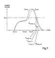
- Figure 7 shows again the course of the future radiation intensity level I anticip and the real façade radiation intensity I façade in one day.
- the radiation intensity falls below the threshold level I thres .
- modified delay time ⁇ anticip, dis can be adjusted as function of the geographical position of the building 10 and/or the façade orientation and/or the date and/or the time and/or the misalignment angle ⁇ and/or similar parameters.
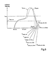
- the threshold level I thres in order to ensure satisfactory functioning of the control system 40, 50, 52, 54, that means to define a lower threshold level I thres, dis for the disappearance of the radiation 60 compared to the threshold level I thres of the appearance of the radiation 60. This is shown schematically in Figure 8 .
- dis it may be necessary to combine the lower threshold level I thres, dis with a further modified delay time ⁇ anticip. dis, thres or not.
- the further modified delay time ⁇ anticip, dis, thres may be longer or preferably shorter compared with the typical modified delay time ⁇ anticip, dis .
- the lower threshold level I thres, dis and/or the further modified delay time ⁇ anticip, dis, thres of the inventive control system 40, 50, 52, 54 may be adjusted as function of the geographical position of the building 10 and/or the façade orientation and/or the date and/or the time and/or and similar parameters.
- This threshold adjustment has for goal, as previously explained, not to control movement of the shading devices when the real façade might still be illuminated by the sun radiations.
- a parameter such as time may enable to distinguish between such situations of disappearance of sun at sunset and a situation of disappearance of sun because of clouds.
- a parameter such as time may enable to distinguish between such situations of disappearance of sun at sunset and a situation of disappearance of sun because of clouds.
- both real and virtual façades receive the same small amount of radiation intensity at the same time.
- the solar protection may then be controlled without delay.
- the adjustment of the modified delay time ⁇ anticip , dis or further modified delay time ⁇ anticip, dis, thres can be accomplished in a different way as well. It can be advantageous, to use the calculated future façade radiation intensity I anticip as described above only for the appearance of the radiation 60, but to calculate future façade radiation intensity I anticip for the disappearance of the radiation 60 with modified delay time ⁇ anticip, dis , respectively further modified delay time ⁇ anticip, dis, thres . In this way the real conditions at the façade 30, 32, 34 are taken into account for the de-activation of the shading devices 20, 22, 24, which allows optimizing user comfort.
- the lower threshold level I thres, die for the disappearance of the radiation 60 may be chosen different to the threshold level I thres for appearance of the radiation 60.
- the lower threshold level I thres, dis can alternatively applied to the real façade radiation intensity I façade at the disappearance of the radiation 60 (not shown in Figure 8 ).
- the further modified delay time ⁇ anticip, dis, thres can be rather short or can be reduced to zero.
- the threshold level I thres can be immediately lowered to the lower threshold level I thres, dis after the first surpass of the threshold level I thres at the appearance of the radiation 60 and the lower threshold level I thres, dis can be applied to the real façade radiation intensity I façade instead of the future façade radiation intensity I anticip at the disappearance of the radiation 60.
- the shading devices 20, 22, 24 are activated after the future façade radiation intensity I anticip has surpassed the threshold level I thres .
- the real façade radiation intensity I façade can be still below the now applicable lower threshold level I thres, dis. which will lead to the deactivation of the shading devices 20, 22, 24.
- a minimum activation time T act can be introduced.
- the control of the shading devices 20, 22, 24 will be only active, when the minimum activation time T act has passed.
- This minimum activation time T act has to be chosen to ensure that the radiation 60 has already surpassed the lower threshold level I thres, dis at the real surface, after surpassing the threshold level I thres at the virtual façade.
- the minimum activation time T act is equivalent to a delay time and may depend on the time and/or date and/or the geographical location of the building 10.
- Figure 10 shows the simulation results for the total energy demand for lighting and cooling of an office during summer as a function of the misalignment angle ⁇ of the radiation sensors 50, 52, 54 compared to the facade orientation. As the lighting energy demand increases with the misalignment angle ⁇ and the cooling energy demand decreases, an optimum misalignment angle ⁇ opt can be determined for a given building 10.
- inventive control system 40, 50, 52, 54 of motorized shading devices 20, 22, 24 described above allows the beforehand detection of future façade radiation intensity I anticip on the associated façade 30, 32, 34. This allows the improved management of the operation of shading devices 20, 22, 24 with respect to energy savings and user comfort.
Landscapes
- Engineering & Computer Science (AREA)
- Structural Engineering (AREA)
- General Engineering & Computer Science (AREA)
- Physics & Mathematics (AREA)
- General Physics & Mathematics (AREA)
- Automation & Control Theory (AREA)
- Architecture (AREA)
- Civil Engineering (AREA)
- Air Conditioning Control Device (AREA)
Priority Applications (1)
| Application Number | Priority Date | Filing Date | Title |
|---|---|---|---|
| EP07012807A EP2009521A1 (de) | 2007-06-29 | 2007-06-29 | Verfahren zur Steuerung von Vorrichtungen zur motorisierten Schattierung und Steuerungssystem |
Applications Claiming Priority (1)
| Application Number | Priority Date | Filing Date | Title |
|---|---|---|---|
| EP07012807A EP2009521A1 (de) | 2007-06-29 | 2007-06-29 | Verfahren zur Steuerung von Vorrichtungen zur motorisierten Schattierung und Steuerungssystem |
Publications (1)
| Publication Number | Publication Date |
|---|---|
| EP2009521A1 true EP2009521A1 (de) | 2008-12-31 |
Family
ID=38621869
Family Applications (1)
| Application Number | Title | Priority Date | Filing Date |
|---|---|---|---|
| EP07012807A Withdrawn EP2009521A1 (de) | 2007-06-29 | 2007-06-29 | Verfahren zur Steuerung von Vorrichtungen zur motorisierten Schattierung und Steuerungssystem |
Country Status (1)
| Country | Link |
|---|---|
| EP (1) | EP2009521A1 (de) |
Cited By (1)
| Publication number | Priority date | Publication date | Assignee | Title |
|---|---|---|---|---|
| AT14856U1 (de) * | 2015-03-31 | 2016-07-15 | Ifn-Holding Ag | Fenster oder Tür |
-
2007
- 2007-06-29 EP EP07012807A patent/EP2009521A1/de not_active Withdrawn
Non-Patent Citations (1)
| Title |
|---|
| A. GUILLEMIN, S. MOLTENI: "An energy-efficient controller for shading devices self-adapting to the user wishes", BUILDING AND ENVIRONMENT, vol. 37, 15 August 2001 (2001-08-15), pages 1091 - 1097, XP002461649 * |
Cited By (1)
| Publication number | Priority date | Publication date | Assignee | Title |
|---|---|---|---|---|
| AT14856U1 (de) * | 2015-03-31 | 2016-07-15 | Ifn-Holding Ag | Fenster oder Tür |
Similar Documents
| Publication | Publication Date | Title |
|---|---|---|
| US12163377B2 (en) | Window treatment control using bright override | |
| EP2357544B1 (de) | Steuerungsmethode für Sonnenschutzelemente mit Steuerugseinheit | |
| US8456729B2 (en) | Weather-responsive shade control system | |
| US20250052113A1 (en) | Photosensitive element assembly | |
| JP4327665B2 (ja) | 電動ブラインドの制御装置 | |
| US10167667B2 (en) | Method for preventing false positive occupancy sensor detections caused by motion | |
| EP2748398B1 (de) | Verfahren zur freigabe eines bewegungsanpassungplans zur verhinderung fehlerhafter positiver anzeigen in bewegungserfassungssystemen | |
| JP5968907B2 (ja) | 周囲光制御 | |
| CN111419067A (zh) | 智能窗帘系统及动态调整窗帘开度的方法 | |
| JP2007120090A (ja) | 日射遮蔽制御装置 | |
| US11248818B2 (en) | Server, air conditioning control system, recording medium, and control method | |
| US20170293270A1 (en) | Learning system for efficient sun-blinds control | |
| EP2944160B1 (de) | Beleuchtungssteuerungsanalysator | |
| JP4893534B2 (ja) | 日射遮蔽制御装置 | |
| JP2003161490A (ja) | 空気調和装置の設定温度制御方法およびその装置 | |
| JP4676298B2 (ja) | 電動ブラインドの制御装置 | |
| JP5178003B2 (ja) | 電動ブラインドの制御装置 | |
| GB2640752A (en) | Adaptive building control system | |
| WO2024236512A1 (en) | Method and cloud server for regulating ambient comfort in a building comprising one or more rooms provided with an electric solar shading device | |
| CN120523064A (zh) | 窗帘自调节方法、装置、窗帘设备及计算机可读介质 | |
| EP3825510A2 (de) | Lichtempfindliche elementanordnung |
Legal Events
| Date | Code | Title | Description |
|---|---|---|---|
| PUAI | Public reference made under article 153(3) epc to a published international application that has entered the european phase |
Free format text: ORIGINAL CODE: 0009012 |
|
| AK | Designated contracting states |
Kind code of ref document: A1 Designated state(s): AT BE BG CH CY CZ DE DK EE ES FI FR GB GR HU IE IS IT LI LT LU LV MC MT NL PL PT RO SE SI SK TR |
|
| AX | Request for extension of the european patent |
Extension state: AL BA HR MK RS |
|
| 17P | Request for examination filed |
Effective date: 20090204 |
|
| 17Q | First examination report despatched |
Effective date: 20090311 |
|
| AKX | Designation fees paid |
Designated state(s): AT BE BG CH CY CZ DE DK EE ES FI FR GB GR HU IE IS IT LI LT LU LV MC MT NL PL PT RO SE SI SK TR |
|
| STAA | Information on the status of an ep patent application or granted ep patent |
Free format text: STATUS: THE APPLICATION IS DEEMED TO BE WITHDRAWN |
|
| 18D | Application deemed to be withdrawn |
Effective date: 20110104 |