EP2009658B1 - Baugruppe eines Schutzschalters - Google Patents
Baugruppe eines Schutzschalters Download PDFInfo
- Publication number
- EP2009658B1 EP2009658B1 EP08158560.6A EP08158560A EP2009658B1 EP 2009658 B1 EP2009658 B1 EP 2009658B1 EP 08158560 A EP08158560 A EP 08158560A EP 2009658 B1 EP2009658 B1 EP 2009658B1
- Authority
- EP
- European Patent Office
- Prior art keywords
- rotor
- disposed
- circuit breaker
- pin
- base
- Prior art date
- Legal status (The legal status is an assumption and is not a legal conclusion. Google has not performed a legal analysis and makes no representation as to the accuracy of the status listed.)
- Active
Links
Images




Classifications
-
- H—ELECTRICITY
- H01—ELECTRIC ELEMENTS
- H01H—ELECTRIC SWITCHES; RELAYS; SELECTORS; EMERGENCY PROTECTIVE DEVICES
- H01H9/00—Details of switching devices, not covered by groups H01H1/00 - H01H7/00
- H01H9/30—Means for extinguishing or preventing arc between current-carrying parts
- H01H9/40—Multiple main contacts for the purpose of dividing the current through, or potential drop along, the arc
-
- H—ELECTRICITY
- H01—ELECTRIC ELEMENTS
- H01H—ELECTRIC SWITCHES; RELAYS; SELECTORS; EMERGENCY PROTECTIVE DEVICES
- H01H1/00—Contacts
- H01H1/12—Contacts characterised by the manner in which co-operating contacts engage
- H01H1/14—Contacts characterised by the manner in which co-operating contacts engage by abutting
- H01H1/20—Bridging contacts
- H01H1/2041—Rotating bridge
- H01H1/205—Details concerning the elastic mounting of the rotating bridge in the rotor
-
- H—ELECTRICITY
- H01—ELECTRIC ELEMENTS
- H01H—ELECTRIC SWITCHES; RELAYS; SELECTORS; EMERGENCY PROTECTIVE DEVICES
- H01H71/00—Details of the protective switches or relays covered by groups H01H73/00 - H01H83/00
- H01H71/02—Housings; Casings; Bases; Mountings
- H01H71/0207—Mounting or assembling the different parts of the circuit breaker
- H01H71/0214—Housing or casing lateral walls containing guiding grooves or special mounting facilities
-
- H—ELECTRICITY
- H01—ELECTRIC ELEMENTS
- H01H—ELECTRIC SWITCHES; RELAYS; SELECTORS; EMERGENCY PROTECTIVE DEVICES
- H01H71/00—Details of the protective switches or relays covered by groups H01H73/00 - H01H83/00
- H01H71/10—Operating or release mechanisms
- H01H71/1009—Interconnected mechanisms
-
- H—ELECTRICITY
- H01—ELECTRIC ELEMENTS
- H01H—ELECTRIC SWITCHES; RELAYS; SELECTORS; EMERGENCY PROTECTIVE DEVICES
- H01H71/00—Details of the protective switches or relays covered by groups H01H73/00 - H01H83/00
- H01H71/10—Operating or release mechanisms
- H01H71/1009—Interconnected mechanisms
- H01H71/1027—Interconnected mechanisms comprising a bidirectional connecting member actuated by the opening movement of one pole to trip a neighbour pole
-
- H—ELECTRICITY
- H01—ELECTRIC ELEMENTS
- H01H—ELECTRIC SWITCHES; RELAYS; SELECTORS; EMERGENCY PROTECTIVE DEVICES
- H01H71/00—Details of the protective switches or relays covered by groups H01H73/00 - H01H83/00
- H01H71/10—Operating or release mechanisms
- H01H71/50—Manual reset mechanisms which may be also used for manual release
- H01H71/52—Manual reset mechanisms which may be also used for manual release actuated by lever
Definitions
- the present disclosure relates generally to circuit breakers and particularly to circuit breaker operation mechanism attachment arrangements.
- Multipole circuit breakers configured to protect multiphase electrical circuits are known in the electrical circuit protection industry.
- the variety of constructions of multipole circuit breakers include blow open and non-blow open contact arms, overcentering and non-overcentering contact arms, single contact pair arrangements with the contact pair at one end of a contact arm and a pivot at the other end thereof, double contact pair arrangements (referred to as rotary breakers) with a contact pair at each end of a contact arm and a contact arm pivot intermediate (typically centrally located between) the two ends, single housing constructions with the circuit breaker components housed within a single case and cover, and cassette type constructions (referred to as cassette breakers) with the current carrying components of each phase housed within a phase cassette and each phase cassette housed within a case and cover that also houses the operating mechanism.
- An amount of energy available to close the contact arms is typically related to forces exerted by springs included within an operating mechanism of the circuit breaker.
- One manner to increase this energy is to increase a size of the springs, which typically results in an accompanying undesired increase of mechanism size.
- many circuit breakers commonly employ operating mechanisms that incorporate components disposed proximate the contact arms, such as central pivots and cross pins that extend in a direction along an axis of a rotor and are disposed across multiple poles of the circuit breaker, proximate more than one set of contact arms corresponding to more than one pole.
- US-B-7 189 935 concerns a contact arm assembly for a multipole circuit breaker according to the preamble of claim 1.
- An operating mechanism is provided to rotate a rotor, which carries multiple contact arm modules of the multipole circuit breaker.
- WO-A-02/082487 concerns a rotary contact circuit breaker having a crank to couple a switching mechanism to a rotary contact pole structure.
- the present invention provides a circuit breaker subassembly as defined in accompanying claim 1.
- An embodiment of the invention includes a multi-pole rotor assembly support that provides a reduction in variation of contact closure depression, and therefore, reduction in variation of contact resistance between the poles of a multipole circuit breaker.
- an interface between the operating mechanism and the rotor assembly is physically and electrically isolated from contact arms of the multiple poles.
- mating bearing surfaces of the rotor assembly and a base of the circuit breaker provide a central support to the rotor assembly.
- Another embodiment provides the rotor assembly made from non-conductive material having a blind hole in which a pin connects the rotor to the operating mechanism, thereby isolating the operating mechanism from the contact arms.
- a further embodiment of the invention includes extension springs disposed within the mechanism in a coaxial parallel arrangement, or one inside another, to provide increased closing energy within a given space.
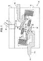
- a circuit breaker 50 (also herein referred to as a circuit breaker subassembly) is depicted in Figure 1 having a base 55 and a cover 60. Within the base 55 and cover 60 are a contact arm assembly 25, a line strap 115, and a load strap 140.
- an operating mechanism 65 with handle 66 is used via a linkage 70 to turn the circuit breaker 50 ON and OFF in a manner that will be described further below.
- Figure 1 illustrates the situation where the operating mechanism 65 has positioned the contact arm assembly 25 in the ON position, creating a CLOSED conduction path 110.
- the conduction path 110 includes a contact arm 100 with movable contacts 125, 130 at opposite ends thereof, the line strap 115, the load strap 140, a fixed contact 120 disposed on the line strap 115, and a fixed contact 135 disposed on the load strap 140.
- Contact arm 100 includes a slotted pivot hole 144 that is centrally disposed between movable contacts 125, 130.
- Operating mechanism 65 opens and closes conduction path 110 via linkage 70 by rotating a rotor 105, which is coupled to and in turn rotates contact arm 100 about its central axis (designated generally by reference numeral 145).
- the rotor 105 is made from non-conductive material. The relationship between contact arm 100 and rotor 105 will be discussed further below.
- Figure 1 illustrates only a single contact arm 100, it will be appreciated that this is for illustration purposes only, as will be evident by the discussion below.
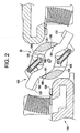
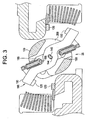
- Figure 3 illustrates an example of the contact arm assembly 25 immediately following the occurrence of an over current condition within the circuit breaker 50 that causes the contact arm 100 to blow open.
- the rotor 105 and side plate 185 have not changed position from the CLOSED position shown in Figure 1 .
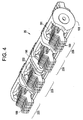
- a four-pole configuration of the contact arm assembly 25 is depicted in isometric view, which a one-piece rotor 105 and four contact arm modules 190. While the embodiment described herein depicts four contact arm modules 220, 225, 230, and 235 (herein referred to generally as contact arm module 190), which may serve to protect phases A, B, C and neutral within a four-pole circuit breaker, it will be appreciated that the disclosed invention is also applicable to other circuit breakers such as a one, two, or three pole circuit breaker, for example.
- FIG. 5 An exemplary contact arm module 190 is shown in Figure 5 , which includes four contact arms 100, eight captivated spring subassemblies 300 (two per contact arm 100), two side plates 185, 186 with notches 175, 180, two spring supports (pins) 155, 160, and one pivot pin 145.
- Each side plate 185, 186 is located on an opposing side of the set of contact arms 100.
- the pivot pin 145 extends through the entire width of the contact arm module 190 from pivot hole 146 in side plate 186 through the pivot hole 144 in each contact arm 100 to pivot hole 146 in side plate 185.
- FIG. 6 illustrates an exemplary one-piece rotor 105.
- the rotor 105 there exist four cavities 200 for the insertion of contact arm modules 190 (also herein referred to as sets of contact arm arms).
- Slot 75 and pin hole 76 are provided to allow the rotor 105 to be mechanically connected with, and electrically isolated from, the linkage 70 and operating mechanism 65, as will be described further below.
- each cavity 200 has sidewalls 201 in which there exists a recess 195.
- the geometry of the recesses 195 include rotor captivating edges 199. These edges interface with mating side plate captivating edges 188 (depicted in Figure 5 on side plate 186) to help retain the side plates 185, 186 within the rotor 105.
- Each of the recesses 195 is designed to accept and contain the geometry of the side plates 185, 186 of the contact arm module 190 shown in Figure 5 .
- the side plates 185, 186 will rotate with the rotor 105.
- the term "close fit" represents a minimum clearance condition with part tolerances considered.
- a different fit may be selected, for example an interference fit.
- Figure 6 in conjunction with Figure 5 , depict sidewalls 201 within each cavity 200 absent any openings between the cavities 200. Therefore, a length of the pivot 145 of each contact arm module 190 is no greater than the distance between the recesses 195. Such openings between cavities 200 may result in a reduced dielectric strength between the poles represented by each contact arm module 190. Accordingly, use of the one-piece, non-conductive rotor absent openings between poles as described herein provides an increased dielectric strength between poles as compared to a rotor or set of rotors that include openings between the contact arm modules 190 corresponding to different circuit breaker 50 poles.
- the operating mechanism 65 has a frame 310 including a first side 315 and a second side 320 disposed within the base 55.
- the linkage 70 (depicted schematically in Figure 1 ) that operatively connects the operating mechanism 65 to the rotor 105 includes lower links 325.
- the lower links 325 are disposed between the sides 315, 320.
- the operating mechanism 65 further includes a handle yoke 330 and two spring assemblies 335, which will be described further below.
- Figure 8 depicts an embodiment of the operating mechanism 65 in operable connection with the rotor 105 corresponding to the ON position of the mechanism 65 (with springs removed for clarity of illustration).
- the mechanism 65 includes a cradle 340 pivotally connected to the frame 310 via a pivot 345.
- An upper link 350 is pivotally connected to the cradle via pivot 355.
- the upper link 350 is further pivotally connected to a toggle pivot 360.
- the lower link 325 is pivotally connected between the toggle pivot 360 and a pivot 365 of the rotor 105.
- the handle yoke 330 is pivotally connected to the frame 310 via pivot 370.
- a lower spring anchor 375 of the spring assembly 335 is in operable connection to the toggle pivot 360 while an upper spring anchor 380 of the spring assembly 335 is operably connectable to the handle yoke 330 via an engagement feature 385, such as a pin through a retention feature 390, such as a hole, in contact with an outer surface 395 of the handle yoke 330 (best seen with reference to Figure 7 ).
- Springs 400 disposed between the lower spring anchor 375 and upper spring anchor 380 are extension springs, and therefore, in an extended state, provide an attractive bias force between the lower spring anchor 375 and upper spring anchor 380.
- a primary latch 405 retains the position of the cradle 340, preventing it from rotating about pivot 345.
- Figure 9 depicts the embodiment of the operating mechanism 65 and rotor 105 of Figure 8 , corresponding to the OFF position of the mechanism 65.
- the handle yoke 330 has been displaced from the ON position (as shown in Figure 8 ) to the OFF position.
- the attractive bias force between the upper spring anchor 380 retained within the handle yoke 330 and the lower spring anchor 375 is applied to the toggle pivot 360 (via the pivotal connection with the lower spring anchor 375) and directed toward the upper spring anchor 380.
- the attractive bias force applied to the toggle pivot 360 is transferred to the upper link 350 and lower link 325 and thereby results in application to the upper link 350 of a moment in a counterclockwise direction about the pivot 355.
- the applied moment causes rotation of the upper link 350 and revolution of the toggle pivot 360 about pivot 355 from the ON position depicted in Figure 8 to the OFF position depicted in Figure 9 .
- motion of the toggle pivot 360 causes a corresponding change in position of a first end 410 of the lower link 325 pivotally connected to the toggle pivot 360.
- a position of the second end 415, pivotally connected to the rotor 105 via pivot 365 is thereby changed, such that the second end 415, the pivot 365, and the rotor 105 rotate about pivot 420 of the rotor 105.
- the contact arm 100 is displaced to the OPEN circuit position.
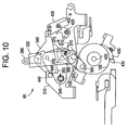
- Figure 10 depicts the embodiment of the operating mechanism 65 and rotor 105 of Figures 8 and 9 , corresponding to a TRIPPED position of the mechanism 65.
- the handle yoke 330 has been displaced from the ON position (as shown in Figure 8 ) to the TRIPPED position, which represents a small clockwise rotation of the handle yoke 330 about the pivot 370.
- the primary latch 405 is rotated clockwise about pivot 425 via a secondary latch 428 to release the cradle 340, in a manner that will be appreciated by one of skill in the art.
- the attractive bias force between the upper spring anchor 380 retained within the handle yoke 330 and the lower spring anchor 375 is applied to the toggle pivot 360.
- the attractive bias force applied to the toggle pivot 360, directed toward the upper spring anchor 380 retained within the handle yoke 330, is transferred to the upper link 350 and lower link 325, and thereby results in application to the upper link 350 of a moment in a counterclockwise direction about the pivot 355.
- the attractive bias force transferred to the upper link 350 is also transferred into the cradle 340 to which the upper link 350 is pivotally connected via pivot 355, and thereby results in application to the cradle 340 of a moment in a counterclockwise direction about the pivot 345.
- the applied moment results in a counterclockwise rotation of the cradle 340 about the pivot 345.
- the counter clockwise rotation of the cradle 340 results in a displacement of the pivot 355, thereby causing displacement of the upper link 350 attached to pivot 355.
- Displacement of the upper link 350 thereby provides an accompanying displacement of the toggle pivot 360, resulting in displacement of the lower link 325 and rotation of the rotor 105 and contact arm 100 to the OPEN position.
- mechanism 65 may be reset, and the cradle 340 returned to the position shown in Figures 8 and 9 via movement of the handle yoke 330 to the OFF position, as depicted in Figure 9 .
- the attractive bias force applied to the toggle pivot 360 will be progressively directed to the reset force direction R, corresponding to the OFF position of the handle yoke 330.
- the attractive bias force in direction R will result in a clockwise rotation of the toggle pivot 360 about the pivot 365.
- Such motion of the toggle pivot 365 will result in application to the upper link 350 of a clockwise moment about pivot 355.
- Contact of a cam surface 440 of the upper link 350 and roller bar 445 attached to the frame 310 prevents clockwise rotation of the upper link 350 about the pivot 355.
- Figure 11 depicts an embodiment of the rotor 105 of the contact arm assembly 25 including a plurality of contact arm modules 190 (also herein referred to as sets of contact arms).
- An axial direction of the rotor 105, which traverses a plurality of phases associated with the plurality of contact arm modules 190 is indicted by direction line X.
- Portions 450 of the rotor 105 are disposed between each contact arm module 190 of the plurality contact arm modules 190 and thereby define separation portions 450 between each contact arm module 190.
- the lower links 325 (best seen with reference to Figure 7 ) are in operable connection with the rotor 105 and disposed at axial positions at the separation portions 450 of the rotor 105.
- lower links 325 are pivotally connected to the rotor 105 via the pivot 365.
- the separation portion 450 includes openings 460, such as holes, and the pivot 365 is a pin 465 disposed within the openings 460 and a matching opening (depicted generally as pivot 365 in Figures 8 through 10 ) disposed at the second end 415 of the lower link 325.
- the opening 460 is a blind hole
- the pin 465 has a length 470 less than an axial length 472 of the blind hole 460. Therefore, because the length of the pin 465, which is less than the length 472 of the separation portion 450 measured along the axial direction of the rotor 105, the pin 465 does not protrude or extend beyond the opening of the blind hole 460 when the pin 465 is bottomed within the blind hole 460.
- connection arrangement including the one-piece rotor 105, reduces variation of contact depression (and therefore contact resistance variation) that results from a cantilevered deflection of cross-pins that extend axially through rotors that correspond to each of a plurality of poles.
- a set of phase isolators 490 disposed within and attached to the base 475 provide a physical insulating barrier between each contact arm module 190, corresponding to different phases of an electrical distribution system (not shown).
- the phase isolators 490 include bearing surfaces 495, also herein referred to as "upper inner bearing surfaces”. Bearing surfaces 495, similar to bearing surfaces 485, mate with the outer bearing surfaces 480 to define the rotational degree of freedom Z of the rotor 105 relative to the base 475. Following disposal of the phase isolators 490 within the base 475, inner bearing surfaces 485, 495 surround the outer bearing surface 480 to restrain the rotor 105 within the base 475, while allowing the defined rotational degree of freedom Z of the rotor 105 relative to the base 475.
- the set of phase isolators 490 are disposed such that blocking surfaces 500 are disposed adjacent to the blind holes 460, and the blocking surfaces 500 block, or close the blind holes 460. Therefore, the blocking surfaces 500 define a first limit of motion of the pin 465 in an axial direction 505 outward from the opening of the blind holes 460. Additionally, the bottom of the blind holes 460 include surfaces 510 opposite the blocking surfaces 500, and the surfaces 510 define a second limit of motion of the pin 465 in an axial direction 505 of the blind holes 460, toward the surfaces 510.
- additional support of the rotor 105 within the base 475 is provided via end supports 515 engaged with ends 520, 525 (along the axial direction) of the rotor 105.
- the pivot 420 of the rotor 105 is a recess 420 disposed within ends 520, 525 and the end support 515 includes protrusions 535 engagable within the recess 420.
- Variations of mating geometry of the protrusion 535 and recess 420 are contemplated, such as a cylinder 540, a cone 545, or a combination thereof, for example.
- the end supports 515 are secured to the base 475.
- the end supports 515 may be mechanically secured to the base 475 via fasteners, such as screws or rivets, or engagement features such as dovetails, for example.
- end supports 515 may be secured to the base via an adhesive or material transformation process, such as brazing or welding for example.
- the end supports 515 or protrusions 535 may be integrated within the base 475.
- end supports 515 and the mating bearing surfaces 480, 485, 495 either exclusive of, or in conjunction with one another provide an arrangement for supporting and allowing rotation of the one piece rotor 105 within the base 475 absent a central pivot that extends through the plurality of contact arm modules 190, and therefore provide an increased dielectric strength, as described above in regard to isolation of the lower links 325.
- Figure 13 depicts an exploded view of the components of the spring assembly 335, including the upper spring anchor 375, the lower spring anchor 380, a first extension spring 560, and a second extension spring 565.
- the first extension spring 560 includes a first end 570, such as a hook, in operable connection with the upper spring anchor via an opening 575 and a second end 580, such as another hook, in operable connection with the lower spring anchor 380 via an opening 585.
- the second extension spring 565 includes spring windings 587 that are disposed coaxial to and surrounding the first extension spring 560 and has a first end 590 in operable connection with the upper spring anchor 375 via a holder 595 disposed between two adjacent spring coil windings, for example.
- a second end 600 of the second extension spring 565 is in operable connection with the lower spring anchor 380 via a holder 605 disposed between two adjacent spring coil windings, for example.
- Use of the second extension spring 565 including the first extension spring 560 in parallel provides an increase in closing energy available to rotate the rotor 105 and the plurality of contact arm assemblies 190 to the CLOSED position, as described above.
- Disposal of the first extension spring 560 coaxially with, and within a center of the spring windings 587 of the second extension spring 565 increases the closing energy without increasing a total outer dimensional envelope corresponding to the second extension spring 565.
- Figure 14 depicts the relationship between the handle yoke 330, the spring assembly 335 and the toggle pivot 360 of the mechanism 65 in response to the mechanism being in the TRIPPED position, as shown in Figure 10 , with the springs 560, 565 in a free, or natural, unextended state.
- the upper spring anchor 375 includes a tool engagement feature 610, such as a hole or an opening. Following attachment of the lower spring anchor 380 to the toggle pin 360, with the toggle pin 360 disposed according to the TRIPPED position, a non-extended state of the springs 560, 565 yields a length of the spring assembly 335 such that the tool engagement feature 610 is disposed accessibly above, or protruding beyond the outer surface 395 of the handle yoke 330. With the tool engagement feature 610 disposed protruding beyond the outer surface 395, a tool (not specifically shown) may be engaged with the tool engagement feature 610 and utilized to apply a force F to extend the springs 560, 565.
Landscapes
- Breakers (AREA)
Claims (13)
- Schutzschalter-Unterbaugruppe (50), umfassend:einen Grundkörper (55);eine Schalteinrichtung (65), die innerhalb des Grundkörpers (55) (475) angeordnet ist;einen einteiligen nichtleitenden Rotor (105), der innerhalb des Grundkörpers (55) (475) angeordnet ist,wobei der Rotor (105) einen Rotationsfreiheitsgrad gegenüber dem Grundkörper (55) (475) hat und in betriebsfähiger Verbindung mit der Steuereinrichtung (65) angeordnet ist;mehrere Kontaktarmsätze (190), die vom Rotor (105) getragen werden, wobei Teile des Rotors (105) zwischen jedem Satz der mehreren Kontaktarmsätze (190) ange-ordnet sind, um Trennabschnitte (450) zu definieren;dadurch gekennzeichnet, dass die Steuereinrichtung (65) Folgendes umfasst:einen Rahmen (310), der innerhalb des Grundkörpers (55) (475) angeordnet ist;ein Gestell (340) in Drehverbindung mit dem Rahmen (310);ein oberes Verbindungsstück (350) in Drehverbindung mit dem Gestell (340); undein unteres Verbindungsstück (325), das ein erstes Ende (410) und ein zweites Ende (415) aufweist, wobei das erste Ende (410) in Drehverbindung mit dem oberen Verbindungsstück (350) ist und das zweite Ende (415) in Drehverbindung mit dem Rotor (105) an den Trennabschnitten (450) ist, unddadurch gekennzeichnet, dass der Grundkörper (55) (475) Folgendes umfasst:eine Endstütze (515), wobei die Endstütze (515) mit mindestens einem Ende (520, 525) des einteiligen, nichtleitenden Rotors (105) entlang einer axialen Richtung (505) desselben einrasten kann.
- Schutzschalter-Unterbaugruppe (50) nach Anspruch 1, die ferner Folgendes umfasst:einen Stift (365) in Drehverbindung mit dem zweiten Ende (415) des unteren Verbindungsstücks (325), wobei der Stift (365) innerhalb eines Lochs (460) des Trennabschnitts (450) des Rotors (105) angeordnet ist, wobei der Stift (365) eine Länge (470) aufweist, die kleiner als eine Länge (472) des Trennabschnitts (450) ist, welche entlang einer axialen Richtung (505) des Rotors (105) gemessen wird.
- Schutzschalter-Unterbaugruppe (50) nach Anspruch 1 oder 2, wobei:der einteilige, nichtleitende Rotor (105) ferner eine Aussparung (455) umfasst, die innerhalb mindestens einer der Trennabschnitte (450) des Rotors (105) angeordnet ist; unddas zweite Ende (415) des unteren Verbindungsstücks (325) innerhalb der Aussparung (75) angeordnet ist.
- Schutzschalter-Unterbaugruppe (50) nach einem der vorherigen Ansprüche, wobei:der Rotor (105) ferner eine äußere Auflagerfläche (480) umfasst;der Grundkörper (475) ferner eine innere Auflagerfläche (485) umfasst;die äußere Auflagerfläche (480) mit der inneren Auflagerfläche (485) zusammenpasst und dadurch den Rotationsfreiheitsgrad des Rotors (105) gegenüber dem Grundkörper (475) definiert.
- Schutzschalter-Unterbaugruppe nach Anspruch 4, wobei die äußere Auflagefläche (480) zwischen zwei Sätzen der mehreren Kontaktarmsätze (190) angeordnet ist.
- Schutzschalter-Unterbaugruppe (50) nach Anspruch 5, wobei die innere Auflagerfläche (485) des Grundkörpers (475) eine untere Innenfläche (475) umfasst, und wobei die Schutzschalter-Unterbaugruppe (50) ferner Folgendes umfasst:einen Phasenisolator (490), die zwischen den beiden Kontaktarmsätzen (190) angeordnet ist, wobei der Phasenisolator (490) eine obere innere Auflagerfläche (495) umfasst, die mit der äußeren Auflagerfläche (480) zusammenpasst.
- Schutzschalter-Unterbaugruppe nach Anspruch 6, wobei die Schutzschalter-Unterbaugruppe ferner Folgendes umfasst:einen Stift in Drehverbindung mit dem zweiten Ende des unteren Verbindungsstücks, wobei der Stift innerhalb eines Lochs des Trennabschnitts des Rotors angeordnet ist, und wobei der Stift eine Länge aufweist, die kleiner als eine Länge des Trennabschnitts ist, welche entlang einer axialen Richtung des Rotors gemessen wird;wobei der Phasenisolator eine Sperroberfläche aufweist, die neben der Öffnung angeordnet ist und dadurch eine Bewegungsbegrenzung des Stifts in einer axialen Richtung der Öffnung definiert.
- Schutzschalter-Unterbaugruppe (50) nach einem der vorherigen Ansprüche, wobei:der Rotor (105) ferner einen ersten Anschlag (430) umfasst;der Grundkörper (55) ferner einen zweiten Anschlag (435) umfasst; undder erste Anschlag (430) und der zweite Anschlag (435) eine Begrenzung des Rotationsfreiheitsgrades des Rotors (105) gegenüber dem Grundkörper (475) definieren.
- Schutzschalter-Unterbaugruppe (50) nach einem der vorherigen Ansprüche, wobei:das Gestell (340) über einen ersten Drehzapfen in Drehverbindung mit dem Rahmen (310) ist;das untere Verbindungsstück (325) über einen Kippbolzen (360) in Drehverbindung mit dem oberen Verbindungsstück (350) ist; undder Steuermechanismus (65) ferner Folgendes umfasst:einen Griffbügel (330), der über einen zweiten Drehzapfen (370) in Drehverbindung mit dem Rahmen (310) ist; undeine Federbaugruppe (335), die Folgendes umfasst:einen oberen Federanker (380), der mit dem Griffbügel (330) betriebsfähig verbunden werden kann;einen unteren Federanker (375) in betriebsfähiger Verbindung mit dem Kippbolzen (360);eine erste Zugfeder (560), die ein erstes Ende (570) in betriebsfähiger Verbindung mit dem oberen Federanker (380) und ein zweites Ende (580) in betriebsfähiger Verbindung mit dem unteren Federanker (375) aufweist;eine zweite Zugfeder (565), die koaxial zur ersten Zugfeder (560) angeordnet ist undFederwickelungen aufweist, welche diese umgeben, wobei die zweite Zugfeder (565) ein erstes Ende (590) in betriebsfähiger Verbindung mit dem oberen Federanker (380) undein zweites Ende (600) in betriebsfähiger Verbindung mit dem unteren Federanker (375) aufweist.
- Schutzschalter-Unterbaugruppe (50) nach Anspruch 9, wobei der obere Federanker (380) ein Werkzeugeingriffsmerkmal (610) umfasst, das über einer äußeren Oberfläche (395) des Griffbügels (330) als Reaktion darauf zugänglich angeordnet ist, dass der untere Federanker (375) in betriebsfähiger Verbindung mit dem Kippbolzen (360) ist, und die erste und zweite Zugfeder (560) sich in einem nicht zugbelasteten Zustand befinden.
- Schutzschalter-Unterbaugruppe (50) nach Anspruch 10, wobei der obere Federanker (380) ferner ein Haltemerkmal (390) derart umfasst, dass das Haltemerkmal so angeordnet ist, dass es über die äußere Oberfläche des Griffbügels (330) vorragend als Reaktion darauf angeordnet ist, dass der untere Federanker in betriebsfähiger Verbindung mit dem Kippbolzen (360) ist und die erste und zweite Zugfeder sich nicht in einem ausgedehnten Zustand befinden.
- Schutzschalter-Unterbaugruppe (50) nach Anspruch 11, die ferner Folgendes umfasst:ein Eingriffsmerkmal (385), das in Kontakt mit dem Haltemerkmal (390) des oberen Federankers (380) und der äußeren Oberfläche des Griffbügels angeordnet ist, wodurch das Haltemerkmal, das über die äußere Oberfläche des Griffbügels (330) hinausragt, festgehalten wird.
- Schutzschalter-Unterbaugruppe nach Anspruch 12, wobei das Eingriffsmerkmal ein Bolzen ist.
Applications Claiming Priority (1)
| Application Number | Priority Date | Filing Date | Title |
|---|---|---|---|
| US11/768,611 US7800007B2 (en) | 2007-06-26 | 2007-06-26 | Circuit breaker subassembly apparatus |
Publications (3)
| Publication Number | Publication Date |
|---|---|
| EP2009658A2 EP2009658A2 (de) | 2008-12-31 |
| EP2009658A3 EP2009658A3 (de) | 2011-10-05 |
| EP2009658B1 true EP2009658B1 (de) | 2014-05-21 |
Family
ID=39769602
Family Applications (1)
| Application Number | Title | Priority Date | Filing Date |
|---|---|---|---|
| EP08158560.6A Active EP2009658B1 (de) | 2007-06-26 | 2008-06-19 | Baugruppe eines Schutzschalters |
Country Status (3)
| Country | Link |
|---|---|
| US (1) | US7800007B2 (de) |
| EP (1) | EP2009658B1 (de) |
| CN (1) | CN101335158B (de) |
Families Citing this family (14)
| Publication number | Priority date | Publication date | Assignee | Title |
|---|---|---|---|---|
| US8214483B2 (en) * | 2007-02-28 | 2012-07-03 | Red Hat, Inc. | Method and system for continuous availability subscription service |
| CN101527232B (zh) * | 2007-12-27 | 2012-07-18 | 拿丁有限责任公司 | 用于开关设备的接触致动装置 |
| US8350168B2 (en) * | 2010-06-30 | 2013-01-08 | Schneider Electric USA, Inc. | Quad break modular circuit breaker interrupter |
| DE102010035625A1 (de) | 2010-08-24 | 2012-03-01 | Siemens Aktiengesellschaft | Elektrischer Schalter und Verfahren zum Montieren einer Schalteinheit eines elektrischen Schalters |
| FR2968828B1 (fr) * | 2010-12-13 | 2012-12-21 | Schneider Electric Ind Sas | Dispositif de coupure ayant plusieurs blocs de coupure unipolaire et comportant un seul mecanisme d'actionnement desdits blocs |
| DE102011003131A1 (de) * | 2011-01-25 | 2012-07-26 | Siemens Aktiengesellschaft | Elektrischer Schalter |
| DE102012201260A1 (de) * | 2012-01-30 | 2013-08-01 | Siemens Aktiengesellschaft | Schalteinheit für ein elektrisches Schaltgerät sowie elektrisches Schaltgerät |
| US9508495B2 (en) * | 2012-03-28 | 2016-11-29 | Larsen & Tourbo Limited | Double break contact system for moulded case circuit breakers |
| KR200472735Y1 (ko) * | 2012-11-01 | 2014-05-20 | 엘에스산전 주식회사 | 배선용 회로차단기의 가동접촉자 및 가동접촉자 어셈블리 |
| CN106030742B (zh) * | 2014-02-17 | 2019-05-21 | 雷比诺有限公司 | 多配置切换组件 |
| US9704684B2 (en) * | 2014-10-08 | 2017-07-11 | General Electric Company | Circuit breaker crossbar assembly |
| DE102014224623A1 (de) * | 2014-12-02 | 2016-06-16 | Siemens Aktiengesellschaft | Rotor und elektromechanische Schaltvorrichtung mit einem Rotor |
| US9576761B2 (en) * | 2015-05-20 | 2017-02-21 | General Electric Company | Circuit breaker crossbar assembly |
| CN111769016B (zh) * | 2020-06-06 | 2022-07-05 | 武汉船用电力推进装置研究所(中国船舶重工集团公司第七一二研究所) | 一种塑壳断路器多触指动触头及触头系统 |
Family Cites Families (22)
| Publication number | Priority date | Publication date | Assignee | Title |
|---|---|---|---|---|
| US3876847A (en) * | 1974-02-28 | 1975-04-08 | Square D Co | Operating mechanism for opening and closing an electrical switch |
| US4644120A (en) * | 1985-07-18 | 1987-02-17 | Westinghouse Electric Corp. | Molded case circuit breaker with a movable lower electrical contact positioned by a torsion spring |
| FR2589626B1 (fr) * | 1985-10-31 | 1989-03-03 | Merlin Gerin | Mecanisme de commande d'un disjoncteur equipe d'un systeme accumulateur d'energie |
| US5025236A (en) * | 1989-09-07 | 1991-06-18 | Fuji Electric Co., Ltd. | Circuit breaker |
| FR2682531B1 (fr) * | 1991-10-15 | 1993-11-26 | Merlin Gerin | Disjoncteur multipolaire a blocs unipolaires. |
| FR2687249B1 (fr) * | 1992-02-07 | 1994-04-01 | Merlin Gerin | Mecanisme de commande d'un disjoncteur a boitier moule. |
| US5539167A (en) * | 1994-02-14 | 1996-07-23 | Square D. Company | Blade suspension assemlby for a circuit breaker |
| US6346868B1 (en) * | 2000-03-01 | 2002-02-12 | General Electric Company | Circuit interrupter operating mechanism |
| US6262644B1 (en) * | 2000-03-08 | 2001-07-17 | General Electric Company | Latch resetting arrangement |
| US6369340B1 (en) * | 2000-03-10 | 2002-04-09 | General Electric Company | Circuit breaker mechanism for a contact system |
| US6459059B1 (en) * | 2000-03-16 | 2002-10-01 | General Electric Company | Return spring for a circuit interrupter operating mechanism |
| US6479774B1 (en) * | 2000-03-17 | 2002-11-12 | General Electric Company | High energy closing mechanism for circuit breakers |
| US6559743B2 (en) * | 2000-03-17 | 2003-05-06 | General Electric Company | Stored energy system for breaker operating mechanism |
| US6423917B2 (en) * | 2000-03-17 | 2002-07-23 | General Electric Company | Self-disengaging circuit breaker motor operator |
| US6373010B1 (en) * | 2000-03-17 | 2002-04-16 | General Electric Company | Adjustable energy storage mechanism for a circuit breaker motor operator |
| WO2002082487A1 (en) * | 2001-04-09 | 2002-10-17 | General Electric Company | Circuit breaker mechanism for a rotary contact system |
| CN1220234C (zh) | 2001-10-30 | 2005-09-21 | 浙江正泰电器股份有限公司 | 一种多极低压双断点塑壳断路器 |
| ITMI20012587A1 (it) * | 2001-12-10 | 2003-06-10 | Abb Service Srl | Albero porta contatti per un interruttore di potenza di bassa tensione |
| ITMI20042234A1 (it) * | 2004-11-19 | 2005-02-19 | Abb Service Srl | Interuttore automatico con cinematismo di sgancio azionato da contatto mobile |
| ITBG20050024A1 (it) * | 2005-05-13 | 2006-11-14 | Abb Service Srl | Interruttore installabile secondo diverse configurazioni operative |
| ITBG20050026A1 (it) * | 2005-05-13 | 2006-11-14 | Abb Service Srl | Interruttore con equipaggio mobile sospeso |
| US7189935B1 (en) * | 2005-12-08 | 2007-03-13 | General Electric Company | Contact arm apparatus and method of assembly thereof |
-
2007
- 2007-06-26 US US11/768,611 patent/US7800007B2/en active Active
-
2008
- 2008-06-19 EP EP08158560.6A patent/EP2009658B1/de active Active
- 2008-06-26 CN CN2008101273706A patent/CN101335158B/zh active Active
Also Published As
| Publication number | Publication date |
|---|---|
| US7800007B2 (en) | 2010-09-21 |
| CN101335158A (zh) | 2008-12-31 |
| CN101335158B (zh) | 2013-05-29 |
| US20090000933A1 (en) | 2009-01-01 |
| EP2009658A2 (de) | 2008-12-31 |
| EP2009658A3 (de) | 2011-10-05 |
Similar Documents
| Publication | Publication Date | Title |
|---|---|---|
| EP2009658B1 (de) | Baugruppe eines Schutzschalters | |
| EP1177567B1 (de) | Betätigungsmechanismus für einen schutzschalter | |
| US5793270A (en) | Circuit breaker with latch preventing rebound of blow open contact arm | |
| US5898146A (en) | Molded case circuit breaker with modular crossbar | |
| EP0353950B1 (de) | Gummianschläge in Aussenpolen | |
| US20030112104A1 (en) | Pressure sensitive trip mechanism for a rotary breaker | |
| US5874699A (en) | Molded case circuit breaker and moving conductor assembly therefor | |
| NZ229871A (en) | Circuit breaker contact arm assembly | |
| WO2003050830A1 (en) | Contact supporting shaft for a low-voltage power circuit breaker | |
| US5686709A (en) | Modular trip bar assembly for multipole circuit breaker | |
| JPH03208223A (ja) | 回路遮断器 | |
| US6590482B2 (en) | Circuit breaker mechanism tripping cam | |
| EP0923103B1 (de) | Bewegliche Kontaktstruktur für Selbstschalter | |
| EP2549499A1 (de) | Elektrisches Schaltgerät und Sekundärauslösungsmechanismus dafür | |
| EP1194941B1 (de) | Rückstellfeder für betätigungsmechanismus eines leistungsschalters | |
| AU623409B2 (en) | A molded case circuit breaker with an unriveted upper link securement | |
| EP0353939A2 (de) | Methode zum schnellen Austauschen eines Stromtransformators | |
| NZ229870A (en) | Circuit breaker auxiliary transformer board acts as barrier | |
| US3414850A (en) | Multi-phase circuit breaker ganging device using circular communication between phases | |
| EP1388158B1 (de) | Schutzschaltermechanismus für drehkontaktsystem | |
| EP0353949B1 (de) | Modulare Auswahlplattenanordnung | |
| JP4262349B2 (ja) | 多極回路遮断器 | |
| WO2025215678A1 (en) | An actuator assembly for a molded case circuit breaker (mccb) | |
| JPH08167366A (ja) | 回路遮断器 | |
| JP2002203466A (ja) | 複数スプリング式ロータ組立体 |
Legal Events
| Date | Code | Title | Description |
|---|---|---|---|
| PUAI | Public reference made under article 153(3) epc to a published international application that has entered the european phase |
Free format text: ORIGINAL CODE: 0009012 |
|
| AK | Designated contracting states |
Kind code of ref document: A2 Designated state(s): AT BE BG CH CY CZ DE DK EE ES FI FR GB GR HR HU IE IS IT LI LT LU LV MC MT NL NO PL PT RO SE SI SK TR |
|
| AX | Request for extension of the european patent |
Extension state: AL BA MK RS |
|
| PUAL | Search report despatched |
Free format text: ORIGINAL CODE: 0009013 |
|
| AK | Designated contracting states |
Kind code of ref document: A3 Designated state(s): AT BE BG CH CY CZ DE DK EE ES FI FR GB GR HR HU IE IS IT LI LT LU LV MC MT NL NO PL PT RO SE SI SK TR |
|
| AX | Request for extension of the european patent |
Extension state: AL BA MK RS |
|
| RIC1 | Information provided on ipc code assigned before grant |
Ipc: H01H 1/20 20060101ALI20110901BHEP Ipc: H01H 71/10 20060101ALN20110901BHEP Ipc: H01H 9/40 20060101AFI20110901BHEP Ipc: H01H 71/02 20060101ALN20110901BHEP Ipc: H01H 71/52 20060101ALN20110901BHEP |
|
| 17P | Request for examination filed |
Effective date: 20120405 |
|
| AKX | Designation fees paid |
Designated state(s): DE FR IT |
|
| GRAP | Despatch of communication of intention to grant a patent |
Free format text: ORIGINAL CODE: EPIDOSNIGR1 |
|
| RIC1 | Information provided on ipc code assigned before grant |
Ipc: H01H 71/52 20060101ALN20131107BHEP Ipc: H01H 71/10 20060101ALN20131107BHEP Ipc: H01H 71/02 20060101ALN20131107BHEP Ipc: H01H 1/20 20060101ALI20131107BHEP Ipc: H01H 9/40 20060101AFI20131107BHEP |
|
| INTG | Intention to grant announced |
Effective date: 20131127 |
|
| RIC1 | Information provided on ipc code assigned before grant |
Ipc: H01H 71/02 20060101ALN20131113BHEP Ipc: H01H 1/20 20060101ALI20131113BHEP Ipc: H01H 71/52 20060101ALN20131113BHEP Ipc: H01H 9/40 20060101AFI20131113BHEP Ipc: H01H 71/10 20060101ALN20131113BHEP |
|
| GRAP | Despatch of communication of intention to grant a patent |
Free format text: ORIGINAL CODE: EPIDOSNIGR1 |
|
| RIC1 | Information provided on ipc code assigned before grant |
Ipc: H01H 71/52 20060101ALN20140218BHEP Ipc: H01H 71/10 20060101ALN20140218BHEP Ipc: H01H 71/02 20060101ALN20140218BHEP Ipc: H01H 1/20 20060101ALI20140218BHEP Ipc: H01H 9/40 20060101AFI20140218BHEP |
|
| GRAS | Grant fee paid |
Free format text: ORIGINAL CODE: EPIDOSNIGR3 |
|
| INTG | Intention to grant announced |
Effective date: 20140317 |
|
| GRAA | (expected) grant |
Free format text: ORIGINAL CODE: 0009210 |
|
| AK | Designated contracting states |
Kind code of ref document: B1 Designated state(s): DE FR IT |
|
| REG | Reference to a national code |
Ref country code: DE Ref legal event code: R096 Ref document number: 602008032376 Country of ref document: DE Effective date: 20140626 |
|
| PGFP | Annual fee paid to national office [announced via postgrant information from national office to epo] |
Ref country code: FR Payment date: 20140617 Year of fee payment: 7 |
|
| REG | Reference to a national code |
Ref country code: DE Ref legal event code: R097 Ref document number: 602008032376 Country of ref document: DE |
|
| PLBE | No opposition filed within time limit |
Free format text: ORIGINAL CODE: 0009261 |
|
| STAA | Information on the status of an ep patent application or granted ep patent |
Free format text: STATUS: NO OPPOSITION FILED WITHIN TIME LIMIT |
|
| 26N | No opposition filed |
Effective date: 20150224 |
|
| PG25 | Lapsed in a contracting state [announced via postgrant information from national office to epo] |
Ref country code: IT Free format text: LAPSE BECAUSE OF FAILURE TO SUBMIT A TRANSLATION OF THE DESCRIPTION OR TO PAY THE FEE WITHIN THE PRESCRIBED TIME-LIMIT Effective date: 20140521 |
|
| REG | Reference to a national code |
Ref country code: DE Ref legal event code: R097 Ref document number: 602008032376 Country of ref document: DE Effective date: 20150224 |
|
| REG | Reference to a national code |
Ref country code: FR Ref legal event code: ST Effective date: 20160229 |
|
| PG25 | Lapsed in a contracting state [announced via postgrant information from national office to epo] |
Ref country code: FR Free format text: LAPSE BECAUSE OF NON-PAYMENT OF DUE FEES Effective date: 20150630 |
|
| REG | Reference to a national code |
Ref country code: DE Ref legal event code: R081 Ref document number: 602008032376 Country of ref document: DE Owner name: ABB S.P.A., IT Free format text: FORMER OWNER: GENERAL ELECTRIC CO., SCHENECTADY, N.Y., US Ref country code: DE Ref legal event code: R081 Ref document number: 602008032376 Country of ref document: DE Owner name: ABB SCHWEIZ AG, CH Free format text: FORMER OWNER: GENERAL ELECTRIC CO., SCHENECTADY, N.Y., US |
|
| REG | Reference to a national code |
Ref country code: DE Ref legal event code: R081 Ref document number: 602008032376 Country of ref document: DE Owner name: ABB S.P.A., IT Free format text: FORMER OWNER: ABB SCHWEIZ AG, BADEN, CH Ref country code: DE Ref legal event code: R082 Ref document number: 602008032376 Country of ref document: DE Representative=s name: DENNEMEYER & ASSOCIATES S.A., DE |
|
| PGFP | Annual fee paid to national office [announced via postgrant information from national office to epo] |
Ref country code: DE Payment date: 20250618 Year of fee payment: 18 |