EP2009662A1 - Interrupteur basculant à plusieurs voies - Google Patents
Interrupteur basculant à plusieurs voies Download PDFInfo
- Publication number
- EP2009662A1 EP2009662A1 EP07012382A EP07012382A EP2009662A1 EP 2009662 A1 EP2009662 A1 EP 2009662A1 EP 07012382 A EP07012382 A EP 07012382A EP 07012382 A EP07012382 A EP 07012382A EP 2009662 A1 EP2009662 A1 EP 2009662A1
- Authority
- EP
- European Patent Office
- Prior art keywords
- tilting
- hinge
- toggle switch
- hinge plate
- axes
- Prior art date
- Legal status (The legal status is an assumption and is not a legal conclusion. Google has not performed a legal analysis and makes no representation as to the accuracy of the status listed.)
- Granted
Links
Images


Classifications
-
- H—ELECTRICITY
- H01—ELECTRIC ELEMENTS
- H01H—ELECTRIC SWITCHES; RELAYS; SELECTORS; EMERGENCY PROTECTIVE DEVICES
- H01H25/00—Switches with compound movement of handle or other operating part
- H01H25/04—Operating part movable angularly in more than one plane, e.g. joystick
- H01H25/041—Operating part movable angularly in more than one plane, e.g. joystick having a generally flat operating member depressible at different locations to operate different controls
-
- G—PHYSICS
- G06—COMPUTING OR CALCULATING; COUNTING
- G06F—ELECTRIC DIGITAL DATA PROCESSING
- G06F3/00—Input arrangements for transferring data to be processed into a form capable of being handled by the computer; Output arrangements for transferring data from processing unit to output unit, e.g. interface arrangements
- G06F3/01—Input arrangements or combined input and output arrangements for interaction between user and computer
- G06F3/03—Arrangements for converting the position or the displacement of a member into a coded form
- G06F3/033—Pointing devices displaced or positioned by the user, e.g. mice, trackballs, pens or joysticks; Accessories therefor
- G06F3/0338—Pointing devices displaced or positioned by the user, e.g. mice, trackballs, pens or joysticks; Accessories therefor with detection of limited linear or angular displacement of an operating part of the device from a neutral position, e.g. isotonic or isometric joysticks
-
- H—ELECTRICITY
- H01—ELECTRIC ELEMENTS
- H01H—ELECTRIC SWITCHES; RELAYS; SELECTORS; EMERGENCY PROTECTIVE DEVICES
- H01H25/00—Switches with compound movement of handle or other operating part
- H01H25/04—Operating part movable angularly in more than one plane, e.g. joystick
- H01H25/041—Operating part movable angularly in more than one plane, e.g. joystick having a generally flat operating member depressible at different locations to operate different controls
- H01H2025/046—Operating part movable angularly in more than one plane, e.g. joystick having a generally flat operating member depressible at different locations to operate different controls having a spherical bearing between operating member and housing or bezel
Definitions
- the present invention relates to a multiway toggle switch according to the preamble of claim 1.
- Such reusable toggle switches are used in a wide variety of electronic devices such as mobile phones, PDAs, (car) radios or navigation systems in order to operate individual functions of the respective device or to be able to navigate through its user interface.
- electronic devices such as mobile phones, PDAs, (car) radios or navigation systems
- many such multi-way toggle switches are not discrete, which means that multiple or even all sides of the switch can be simultaneously undesirably actuated, which may result in multiple movable contacts simultaneously contacting their associated stationary contacts.
- this toggle switch is subject to wear caused by the fact that each time the toggle switch its toggle key comes into frictional contact with said projections, whereby the projections are worn over time, so that an unwanted Mehrfachrome ist in this toggle switch not permanently excluded can be.
- the invention has for its object to further develop a reusable toggle switch according to the preamble of claim 1 that an unwanted Mehrfachrome ist can be permanently excluded.
- the reusable toggle switch comprises a hinge plate with a plurality of intersecting and parallel to the tilt axes of the tilting hinge hinge axes around which deforms the hinge plate at a tilt of the tilt button for transmitting the tilting movement of the tilt button on the movable contacts ,
- the hinge plate In the case of a tilting of the tilting key about a first tilting axis, the hinge plate thereby deforms about an associated first hinge axis such that it blocks a simultaneous tilting of the tilting key about a second tilting axis crossing the first tilting axis.
- the invention is based on the finding that when the hinge plate was deliberately deformed by tilting the tilting key about a first tilting axis about an associated first hinge axis, it is then impossible to simultaneously tilt the tilting key about a second tilting axis crossing the first tilting axis such tilting is prevented by the hinge plate deformed about the first hinge axis.
- the intersecting hinge axes mutually subdivided into a plurality of hinge axis sections, so that the hinge axis sections of the hinge axis crossing the first hinge axis intersect when the hinge plate was deformed at the tilting of the tilting button about the first tilting axis about the associated first hinge axis.
- the hinge axis sections of the hinge axes crossing the first hinge axis intersect, it is impossible to deform the hinge plate about these hinge axis sections, which reliably counteracts unwanted multiple contacting of the multiway toggle switch.
- the multi-way toggle switch according to the invention may be formed as a four-way toggle switch, which means that the circuit board has four diamond-shaped arranged, in particular the vertices of a square defining stationary contacts. In a corresponding manner, four movable contacts are present in this case, which are also arranged diamond-shaped or square.
- the hinge plate has at least two mutually perpendicular hinge axes, so that the tilt button in a corresponding manner to two tilting axes perpendicular to each other can be tilted.
- the tilting and hinge axes run parallel to the diagonals of said diamonds or squares, so that when the tilting key is tilted about a tilting axis, targeted contacting of those contacts is achieved which lie on the respective other diagonal.
- the hinge plate has only two perpendicular crossing hinge axes, however, it may prove advantageous to form the hinge plate with four hinge axes, which are oriented so that the hinge plate is divided into nine areas.
- the hinge plate has two pairs of parallel hinge axes, with one pair crossing the other pair vertically. In this way, the hinge plate is divided into three times three, so nine areas.
- This embodiment proves to be advantageous in that thereby the area lying in the middle of the three times three areas can be used for fastening purposes of the hinge plate, since in this case only the eight edge areas are subjected to a deformation.
- the hinge plate can be made in one piece from a permanently elastic plastic material, wherein the hinge axes are formed by film hinges, which flexibly and movably the adjacent areas of the hinge plate connect.
- the hinge plate is thus designed as a single, one-piece part, which can be produced inexpensively, for example by means of an injection molding process. Because of the hinge plate is made of a durable elastic material, there is no mechanical wear along the hinge axes formed by the film hinges, which the risk of Mehrfachrome réelle can be permanently excluded with the reusable toggle switch according to the invention.
- the hinge plate can also be made of a permanently elastic metal, in particular spring steel, in which the hinge axes are impressed.
- the multi-way toggle switch may further comprise a holding body attached to the circuit board to which the hinge plate is attached.
- the tilt button can be mounted on the holding body, for example via a ball joint.
- the toggle button of the multi-way toggle switch can be provided with markings indicating the desired tilting directions of the switch, it is undesirable for the tilt button to be twisted, as the marks would then be pointing in wrong directions.
- the holding body and the tilting key can have mutually coordinated engagement sections in such a manner that they engage with each other, but at the same time allow tilting of the tilting button about its tilting axes.
- the holding body can be composed of an upper part and a lower part, wherein the hinge plate is arranged between the two parts.
- the unit of holding body and hinge plate can thereby already before the actual assembly of the reusable toggle switch be pre-assembled, whereby the actual assembly of the reusable toggle switch can be performed time-saving.
- the hinge plate is preferably received by the latter and thus the deformation of the hinge plate can not be transferred directly to the movable contacts, the individual contacts associated transmission elements are further provided which the deformation of the hinge plate due to tilting of the tilt button transmit the moving contacts.
- the holding body may have a plurality of guides, in particular four guides, which each receive a transmission element slidably.
- the transmission elements are in contact with the underside of the hinge plate, so that caused by a tilting of the tilting button deformation of the hinge plate is transmitted to an associated movable contact.
- the transmission elements may have openings which are aligned with corresponding openings in the holder body and in the hinge plate. In this way, the tilting button can be backlit by means of at least one light source arranged on the printed circuit board, without having to equip the tilting key itself with corresponding lighting means.
- the individual transmission elements can be connected to each other via elastic spring arms, which, for example, a spiral Shape to wind at least partially around the transmission elements around.
- elastic spring arms By connecting the transmission elements via said spring arms, the transmission elements can be mounted faster because not every transmission element must be installed individually.
- the spring arms do not obstruct the displaceability of the transmission elements, since they are made on the one hand as the transmission elements of a resilient plastic material and on the other hand their elasticity is supported by the spiral shape.
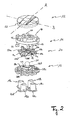
- the illustrated multi-way toggle switch 10 has, viewed from top to bottom, a circular tilting key 12, a housing 42 with a circular opening for receiving the tilting key 12, an upper holding body portion 14, a hinge plate 20, a lower one Holding body part 16, four connected by spring arms 40a, 40b, 40c, 40d transmission elements 18a, 18b, 18c, 18d, an elastic switching mat 26 and a circuit board 22 on.
- the printed circuit board 22 has four stationary contacts 24a, 24b, 24c, 24d, which are arranged at a uniform angular distance of about 90 ° around a point corresponding to the center of the tilting key 12.
- four upwardly open, elastic elevations 28a, 28b, 28c, 28d are formed on the elastic switching mat 26, which comprise on the inside of their upper end surfaces not shown movable, circular contact elements which the stationary contacts 24a, 24b, 24c , 24d of the circuit board 22 each spaced from each other.
- the elastic elevations 28a, 28b, 28c, 28d are reversibly deformable in the vertical direction and designed such that they buckle when a predetermined compressive force is exceeded in order to generate a perceptible for an operator shift feel.
- the tilting button 12 In order to apply the required compressive force for buckling of the transmission elements 18a, 18b, 18c, 18d and for closing the contacts 24a, 24b, 24c, 24d, the tilting button 12, which protrudes from the circular opening of the housing 42 partially to one of Operator to be pressed. How the particular Fig. 3 can be removed, the toggle button 12 is pivotally mounted via a ball joint 36 on the upper holding body part 14, which in turn with a plurality of pins 32 (FIG. Fig. 2 ) on the printed circuit board 22 (FIG. Fig. 1 ) is attached. The pins 32 protrude through corresponding openings in the lower Holding body 16 therethrough, which in turn has an upstanding spherical body for producing said articulated connection 36 with the tilting key 12.
- the lower holding part 16 further has four tubular guide openings 38a, 38b, 38c, 38d, which are arranged at a uniform angular distance of approximately 90 ° about a point corresponding to the center of the tilting button 12 around.
- the guide openings 38a, 38b, 38c, 38d receive the transmission elements 18a, 18b, 18c, 18d so that they are slidably mounted in the guide openings 38a, 38b, 38c, 38d in order to exert a compressive force on the tilting button 12 by tilting Transmission elements 18a, 18b, 18c, 18d to be able to apply to the elevations 28a, 28b, 28c, 28d.
- the Mehrwegkippschalter 10 therefore has the hinge plate 20, which has two pairs of parallel hinge axes a 1 , a 2 , b 1 , b 2 , wherein the one Pair a 1 , a 2 the other pair b 1 , b 2 crosses vertically.
- the hinge axes a 1 , a 2 of the hinge plate 20 extend parallel to the tilt axis A of the tilting button 12 and the hinge axes b 1 , b 2 extend in a corresponding manner parallel to the tilt axis B of the tilting key 12.
- the hinge axes a 1 , a 2 , b 1 , b 2 the hinge plate 20 is divided into three times three, so nine areas.
- the hinge plate 20 can be, for example, an approximately circular disk made of an elastic plastic material, in which the hinge axes a 1 , a 2 , b 1 , b 2 are formed by film hinges. However, it would also be possible to manufacture the hinge plate 20 from a spring steel and to impress the hinge axes a 1 , a 2 , b 1 , b 2 therein.
- the hinge plate 20 To attach the hinge plate 20 to the lower support body part 16, the hinge plate 20 has an opening 30 in the middle to be received by a corresponding circular seat 44 on the lower support body part 16.
- the hinge plate 20 serves, for example, in the event of a tilting of the tilting key 12 about the tilting axis B, a simultaneous tilting of the tilting key 12 about the tilting axis A is blocked. This is due to the fact that with a tilting of the tilting button 12 about the tilt axis B, the hinge plate 20 is deformed about the hinge axis b1 so that it can not be bent simultaneously about one of the hinge axes a 1 , a 2 .
- the tilt button 12 is tilted about the axis B, as shown in the Fig. 2 and 3 is shown, this results in that the three adjacent to the hinge axis b1 edge regions of the hinge plate 20 are bent down or tilted.
- the transmission element 18d is displaced translationally downward at the same time, so that ultimately the projection 28d buckles, resulting in a contacting of the stationary contact 24d on the circuit board 22.
- the tilting button 12 Since a direct contact of the middle edge regions of the hinge plate 20 is prevented by the tilting button 12 by the upstanding projections 46 on the upper side of the upper holding body part 14, the tilting button 12 has a downwardly directed cylinder wall 52 and the middle edge regions of the tilting button 12 are with radially projecting actuating projections 50a, 50b, 50c, 50d, which extend between the projections 46 in the radial direction further than the projections 46 to the outside.
- the cylinder wall 52 of the tilting key 12 does not collide with the projections 46 but rather comes into abutment with one of the actuating projections 50a, 50b, 50c, 50d, whereby the desired deformation of the hinge plate 20 can be caused.
- the multi-way toggle switch 10 is designed such that defined light passageways between those on the Printed circuit board 22 located light sources (not shown) and the tilting button 12 are generated.
- elevations 28a, 28b, 28c, 28d are provided at its upper end surface in the same manner as the central edge regions of the hinge plate 20 with openings 34a, 34b, 34d, so that light rays from which on the circuit board 22nd light sources are transmitted, can pass through the elevations 28a, 28b, 28c, 28d and the tubular transmission elements 18a, 18b, 18c, 18d and the hinge plate 20 up to the tilt button 12 to backlight their tilting marks (not shown).
- the hinge plate 20 is disposed between the tilting key 12 and the transmission members 18a, 18b, 18c, 18d. In fact, however, the positioning of the hinge plate 20 is not critical. In principle, the hinge plate 20 can namely be arranged at any point in the path of action between the tilting key 12 and the contacts of the multiway toggle switch 10, such as between the transmission elements 18a, 18b, 18c, 18d and the elastic switching mat 26.
- the multi-way toggle switch 10 shown in the figures instead of a hinge plate 20, which two pairs of vertically crossing hinge axes a 1 , a 2 ; b 1 , b 2 , may also be equipped with a hinge plate, which has only two vertically intersecting hinge axes.
- the hinge plate would be divided into four equal areas, the hinge axes are equally parallel to the tilt axes A, B of the tilting button 12 and interrupted by the openings 34a, 34b, 34c, 34d.
Landscapes
- Engineering & Computer Science (AREA)
- General Engineering & Computer Science (AREA)
- Theoretical Computer Science (AREA)
- Human Computer Interaction (AREA)
- Physics & Mathematics (AREA)
- General Physics & Mathematics (AREA)
- Switches With Compound Operations (AREA)
- Switches That Are Operated By Magnetic Or Electric Fields (AREA)
- Mobile Radio Communication Systems (AREA)
- Use Of Switch Circuits For Exchanges And Methods Of Control Of Multiplex Exchanges (AREA)
Priority Applications (3)
| Application Number | Priority Date | Filing Date | Title |
|---|---|---|---|
| DE502007001308T DE502007001308D1 (de) | 2007-06-25 | 2007-06-25 | Mehrweg-Kippschalter |
| EP07012382A EP2009662B1 (fr) | 2007-06-25 | 2007-06-25 | Interrupteur basculant à plusieurs voies |
| AT07012382T ATE439678T1 (de) | 2007-06-25 | 2007-06-25 | Mehrweg-kippschalter |
Applications Claiming Priority (1)
| Application Number | Priority Date | Filing Date | Title |
|---|---|---|---|
| EP07012382A EP2009662B1 (fr) | 2007-06-25 | 2007-06-25 | Interrupteur basculant à plusieurs voies |
Publications (2)
| Publication Number | Publication Date |
|---|---|
| EP2009662A1 true EP2009662A1 (fr) | 2008-12-31 |
| EP2009662B1 EP2009662B1 (fr) | 2009-08-12 |
Family
ID=38293363
Family Applications (1)
| Application Number | Title | Priority Date | Filing Date |
|---|---|---|---|
| EP07012382A Active EP2009662B1 (fr) | 2007-06-25 | 2007-06-25 | Interrupteur basculant à plusieurs voies |
Country Status (3)
| Country | Link |
|---|---|
| EP (1) | EP2009662B1 (fr) |
| AT (1) | ATE439678T1 (fr) |
| DE (1) | DE502007001308D1 (fr) |
Cited By (1)
| Publication number | Priority date | Publication date | Assignee | Title |
|---|---|---|---|---|
| WO2018177964A1 (fr) * | 2017-03-29 | 2018-10-04 | Dav | Ensemble d'éléments de transmission de force pour commutateur |
Citations (3)
| Publication number | Priority date | Publication date | Assignee | Title |
|---|---|---|---|---|
| DE19517538A1 (de) * | 1994-05-12 | 1995-11-30 | Alps Electric Co Ltd | Mehrweg-Kippschalter |
| JP2000268678A (ja) * | 1999-03-19 | 2000-09-29 | Teikoku Tsushin Kogyo Co Ltd | 多方向押圧型スイッチ及び押圧型スイッチ |
| DE10151603C1 (de) * | 2001-10-18 | 2003-03-20 | Kostal Leopold Gmbh & Co Kg | Mehrwege-Schalteranordnung, sowie Schalterbaustein |
-
2007
- 2007-06-25 AT AT07012382T patent/ATE439678T1/de active
- 2007-06-25 DE DE502007001308T patent/DE502007001308D1/de not_active Expired - Fee Related
- 2007-06-25 EP EP07012382A patent/EP2009662B1/fr active Active
Patent Citations (3)
| Publication number | Priority date | Publication date | Assignee | Title |
|---|---|---|---|---|
| DE19517538A1 (de) * | 1994-05-12 | 1995-11-30 | Alps Electric Co Ltd | Mehrweg-Kippschalter |
| JP2000268678A (ja) * | 1999-03-19 | 2000-09-29 | Teikoku Tsushin Kogyo Co Ltd | 多方向押圧型スイッチ及び押圧型スイッチ |
| DE10151603C1 (de) * | 2001-10-18 | 2003-03-20 | Kostal Leopold Gmbh & Co Kg | Mehrwege-Schalteranordnung, sowie Schalterbaustein |
Cited By (2)
| Publication number | Priority date | Publication date | Assignee | Title |
|---|---|---|---|---|
| WO2018177964A1 (fr) * | 2017-03-29 | 2018-10-04 | Dav | Ensemble d'éléments de transmission de force pour commutateur |
| FR3064813A1 (fr) * | 2017-03-29 | 2018-10-05 | Dav | Ensemble d'elements de transmission de force pour commutateur |
Also Published As
| Publication number | Publication date |
|---|---|
| DE502007001308D1 (de) | 2009-09-24 |
| EP2009662B1 (fr) | 2009-08-12 |
| ATE439678T1 (de) | 2009-08-15 |
Similar Documents
| Publication | Publication Date | Title |
|---|---|---|
| DE19844336C1 (de) | Elektrischer Schalter | |
| EP0828207A2 (fr) | Partie supérieure d'un bouton tournant | |
| DE112017007234B4 (de) | Schalter | |
| DE2515185C3 (de) | Elektrischer Schnappschalter | |
| DE2411426B2 (de) | Druckknopfschalter für elektronische Rechner o.dgl | |
| EP1807906A1 (fr) | Connecteur enfichable pour cartes de circuits imprimes | |
| LU92994B1 (de) | Tragschienenbaugruppe mit einem Bussystem und einem eine Leiterplatte aufweisenden Elektronikgerät | |
| DE2806713B2 (de) | Elektrischer Schalter mit in Durchbrüchen angeordneten feststehenden Kontakten | |
| EP2009662B1 (fr) | Interrupteur basculant à plusieurs voies | |
| DE60020284T2 (de) | Tastschalter | |
| DE10260241B4 (de) | Kontaktierungsbauteil und Verfahren zur Herstellung eines Kontaktierungsbauteils | |
| EP1570631B1 (fr) | Dispositif d'entree, notamment pour un telephone portable, module comportant un tel dispositif d'entree, telephone portable et procede de production correspondant | |
| EP1482527B1 (fr) | Interrupteur à bouton poussoir | |
| WO2007009574A1 (fr) | Commutateur a plusieurs niveaux | |
| DE3107316A1 (de) | "schiebeschalter" | |
| EP4288988B1 (fr) | Plaque avant pour un dispositif d'installation électrique | |
| DE2827854C2 (de) | Elektrischer Wippenschalter | |
| DE10027357C2 (de) | Relais mit Handbetätigungseinrichtung und Taste | |
| DE19906037A1 (de) | Schalter, insbesondere Kfz-Bremslichtschalter | |
| DE10037155B4 (de) | Verfahren zur Herstellung eines Kippschalters sowie Kippschalter | |
| DE10013630C2 (de) | Elektrischer Schalter | |
| EP3734629B1 (fr) | Dispositif de commutation | |
| DE10037156B4 (de) | Verfahren zur Herstellung von Schaltelementen sowie Schaltelement | |
| DE10227400A1 (de) | Befestigung mindestens einer Betätigungswippe an der Schaltwippe eines elektrischen Schaltgerätes | |
| DE19511989C2 (de) | Elektrische Schaltvorrichtung |
Legal Events
| Date | Code | Title | Description |
|---|---|---|---|
| PUAI | Public reference made under article 153(3) epc to a published international application that has entered the european phase |
Free format text: ORIGINAL CODE: 0009012 |
|
| 17P | Request for examination filed |
Effective date: 20070907 |
|
| AK | Designated contracting states |
Kind code of ref document: A1 Designated state(s): AT BE BG CH CY CZ DE DK EE ES FI FR GB GR HU IE IS IT LI LT LU LV MC MT NL PL PT RO SE SI SK TR |
|
| AX | Request for extension of the european patent |
Extension state: AL BA HR MK RS |
|
| GRAP | Despatch of communication of intention to grant a patent |
Free format text: ORIGINAL CODE: EPIDOSNIGR1 |
|
| GRAS | Grant fee paid |
Free format text: ORIGINAL CODE: EPIDOSNIGR3 |
|
| GRAA | (expected) grant |
Free format text: ORIGINAL CODE: 0009210 |
|
| AK | Designated contracting states |
Kind code of ref document: B1 Designated state(s): AT BE BG CH CY CZ DE DK EE ES FI FR GB GR HU IE IS IT LI LT LU LV MC MT NL PL PT RO SE SI SK TR |
|
| REG | Reference to a national code |
Ref country code: GB Ref legal event code: FG4D Free format text: NOT ENGLISH |
|
| REG | Reference to a national code |
Ref country code: CH Ref legal event code: EP |
|
| AKX | Designation fees paid |
Designated state(s): AT BE BG CH CY CZ DE DK EE ES FI FR GB GR HU IE IS IT LI LT LU LV MC MT NL PL PT RO SE SI SK TR |
|
| REG | Reference to a national code |
Ref country code: IE Ref legal event code: FG4D |
|
| REF | Corresponds to: |
Ref document number: 502007001308 Country of ref document: DE Date of ref document: 20090924 Kind code of ref document: P |
|
| LTIE | Lt: invalidation of european patent or patent extension |
Effective date: 20090812 |
|
| PG25 | Lapsed in a contracting state [announced via postgrant information from national office to epo] |
Ref country code: IS Free format text: LAPSE BECAUSE OF FAILURE TO SUBMIT A TRANSLATION OF THE DESCRIPTION OR TO PAY THE FEE WITHIN THE PRESCRIBED TIME-LIMIT Effective date: 20091212 Ref country code: LT Free format text: LAPSE BECAUSE OF FAILURE TO SUBMIT A TRANSLATION OF THE DESCRIPTION OR TO PAY THE FEE WITHIN THE PRESCRIBED TIME-LIMIT Effective date: 20090812 Ref country code: SE Free format text: LAPSE BECAUSE OF FAILURE TO SUBMIT A TRANSLATION OF THE DESCRIPTION OR TO PAY THE FEE WITHIN THE PRESCRIBED TIME-LIMIT Effective date: 20090812 Ref country code: FI Free format text: LAPSE BECAUSE OF FAILURE TO SUBMIT A TRANSLATION OF THE DESCRIPTION OR TO PAY THE FEE WITHIN THE PRESCRIBED TIME-LIMIT Effective date: 20090812 Ref country code: ES Free format text: LAPSE BECAUSE OF FAILURE TO SUBMIT A TRANSLATION OF THE DESCRIPTION OR TO PAY THE FEE WITHIN THE PRESCRIBED TIME-LIMIT Effective date: 20091123 |
|
| NLV1 | Nl: lapsed or annulled due to failure to fulfill the requirements of art. 29p and 29m of the patents act | ||
| PG25 | Lapsed in a contracting state [announced via postgrant information from national office to epo] |
Ref country code: PL Free format text: LAPSE BECAUSE OF FAILURE TO SUBMIT A TRANSLATION OF THE DESCRIPTION OR TO PAY THE FEE WITHIN THE PRESCRIBED TIME-LIMIT Effective date: 20090812 Ref country code: LV Free format text: LAPSE BECAUSE OF FAILURE TO SUBMIT A TRANSLATION OF THE DESCRIPTION OR TO PAY THE FEE WITHIN THE PRESCRIBED TIME-LIMIT Effective date: 20090812 Ref country code: SI Free format text: LAPSE BECAUSE OF FAILURE TO SUBMIT A TRANSLATION OF THE DESCRIPTION OR TO PAY THE FEE WITHIN THE PRESCRIBED TIME-LIMIT Effective date: 20090812 Ref country code: NL Free format text: LAPSE BECAUSE OF FAILURE TO SUBMIT A TRANSLATION OF THE DESCRIPTION OR TO PAY THE FEE WITHIN THE PRESCRIBED TIME-LIMIT Effective date: 20090812 |
|
| REG | Reference to a national code |
Ref country code: IE Ref legal event code: FD4D |
|
| PG25 | Lapsed in a contracting state [announced via postgrant information from national office to epo] |
Ref country code: BG Free format text: LAPSE BECAUSE OF FAILURE TO SUBMIT A TRANSLATION OF THE DESCRIPTION OR TO PAY THE FEE WITHIN THE PRESCRIBED TIME-LIMIT Effective date: 20091112 Ref country code: PT Free format text: LAPSE BECAUSE OF FAILURE TO SUBMIT A TRANSLATION OF THE DESCRIPTION OR TO PAY THE FEE WITHIN THE PRESCRIBED TIME-LIMIT Effective date: 20091212 |
|
| PG25 | Lapsed in a contracting state [announced via postgrant information from national office to epo] |
Ref country code: EE Free format text: LAPSE BECAUSE OF FAILURE TO SUBMIT A TRANSLATION OF THE DESCRIPTION OR TO PAY THE FEE WITHIN THE PRESCRIBED TIME-LIMIT Effective date: 20090812 Ref country code: CZ Free format text: LAPSE BECAUSE OF FAILURE TO SUBMIT A TRANSLATION OF THE DESCRIPTION OR TO PAY THE FEE WITHIN THE PRESCRIBED TIME-LIMIT Effective date: 20090812 Ref country code: DK Free format text: LAPSE BECAUSE OF FAILURE TO SUBMIT A TRANSLATION OF THE DESCRIPTION OR TO PAY THE FEE WITHIN THE PRESCRIBED TIME-LIMIT Effective date: 20090812 Ref country code: RO Free format text: LAPSE BECAUSE OF FAILURE TO SUBMIT A TRANSLATION OF THE DESCRIPTION OR TO PAY THE FEE WITHIN THE PRESCRIBED TIME-LIMIT Effective date: 20090812 Ref country code: IE Free format text: LAPSE BECAUSE OF FAILURE TO SUBMIT A TRANSLATION OF THE DESCRIPTION OR TO PAY THE FEE WITHIN THE PRESCRIBED TIME-LIMIT Effective date: 20090812 |
|
| PG25 | Lapsed in a contracting state [announced via postgrant information from national office to epo] |
Ref country code: SK Free format text: LAPSE BECAUSE OF FAILURE TO SUBMIT A TRANSLATION OF THE DESCRIPTION OR TO PAY THE FEE WITHIN THE PRESCRIBED TIME-LIMIT Effective date: 20090812 |
|
| PLBE | No opposition filed within time limit |
Free format text: ORIGINAL CODE: 0009261 |
|
| STAA | Information on the status of an ep patent application or granted ep patent |
Free format text: STATUS: NO OPPOSITION FILED WITHIN TIME LIMIT |
|
| 26N | No opposition filed |
Effective date: 20100517 |
|
| PG25 | Lapsed in a contracting state [announced via postgrant information from national office to epo] |
Ref country code: GR Free format text: LAPSE BECAUSE OF FAILURE TO SUBMIT A TRANSLATION OF THE DESCRIPTION OR TO PAY THE FEE WITHIN THE PRESCRIBED TIME-LIMIT Effective date: 20091113 |
|
| BERE | Be: lapsed |
Owner name: DELPHI TECHNOLOGIES, INC. Effective date: 20100630 |
|
| PG25 | Lapsed in a contracting state [announced via postgrant information from national office to epo] |
Ref country code: MC Free format text: LAPSE BECAUSE OF NON-PAYMENT OF DUE FEES Effective date: 20100630 |
|
| REG | Reference to a national code |
Ref country code: FR Ref legal event code: ST Effective date: 20110228 |
|
| PG25 | Lapsed in a contracting state [announced via postgrant information from national office to epo] |
Ref country code: MT Free format text: LAPSE BECAUSE OF FAILURE TO SUBMIT A TRANSLATION OF THE DESCRIPTION OR TO PAY THE FEE WITHIN THE PRESCRIBED TIME-LIMIT Effective date: 20090812 Ref country code: DE Free format text: LAPSE BECAUSE OF NON-PAYMENT OF DUE FEES Effective date: 20110101 |
|
| PG25 | Lapsed in a contracting state [announced via postgrant information from national office to epo] |
Ref country code: FR Free format text: LAPSE BECAUSE OF NON-PAYMENT OF DUE FEES Effective date: 20100630 |
|
| PG25 | Lapsed in a contracting state [announced via postgrant information from national office to epo] |
Ref country code: BE Free format text: LAPSE BECAUSE OF NON-PAYMENT OF DUE FEES Effective date: 20100630 |
|
| PGFP | Annual fee paid to national office [announced via postgrant information from national office to epo] |
Ref country code: IT Payment date: 20100630 Year of fee payment: 4 |
|
| REG | Reference to a national code |
Ref country code: CH Ref legal event code: PL |
|
| GBPC | Gb: european patent ceased through non-payment of renewal fee |
Effective date: 20110625 |
|
| PG25 | Lapsed in a contracting state [announced via postgrant information from national office to epo] |
Ref country code: LI Free format text: LAPSE BECAUSE OF NON-PAYMENT OF DUE FEES Effective date: 20110630 Ref country code: CH Free format text: LAPSE BECAUSE OF NON-PAYMENT OF DUE FEES Effective date: 20110630 |
|
| PG25 | Lapsed in a contracting state [announced via postgrant information from national office to epo] |
Ref country code: GB Free format text: LAPSE BECAUSE OF NON-PAYMENT OF DUE FEES Effective date: 20110625 |
|
| PG25 | Lapsed in a contracting state [announced via postgrant information from national office to epo] |
Ref country code: CY Free format text: LAPSE BECAUSE OF FAILURE TO SUBMIT A TRANSLATION OF THE DESCRIPTION OR TO PAY THE FEE WITHIN THE PRESCRIBED TIME-LIMIT Effective date: 20090812 |
|
| PG25 | Lapsed in a contracting state [announced via postgrant information from national office to epo] |
Ref country code: LU Free format text: LAPSE BECAUSE OF NON-PAYMENT OF DUE FEES Effective date: 20100625 Ref country code: HU Free format text: LAPSE BECAUSE OF FAILURE TO SUBMIT A TRANSLATION OF THE DESCRIPTION OR TO PAY THE FEE WITHIN THE PRESCRIBED TIME-LIMIT Effective date: 20100213 |
|
| PG25 | Lapsed in a contracting state [announced via postgrant information from national office to epo] |
Ref country code: TR Free format text: LAPSE BECAUSE OF FAILURE TO SUBMIT A TRANSLATION OF THE DESCRIPTION OR TO PAY THE FEE WITHIN THE PRESCRIBED TIME-LIMIT Effective date: 20090812 |
|
| REG | Reference to a national code |
Ref country code: AT Ref legal event code: MM01 Ref document number: 439678 Country of ref document: AT Kind code of ref document: T Effective date: 20120625 |
|
| PG25 | Lapsed in a contracting state [announced via postgrant information from national office to epo] |
Ref country code: AT Free format text: LAPSE BECAUSE OF NON-PAYMENT OF DUE FEES Effective date: 20120625 |