EP2009668A1 - Lampe à décharge avec culot unique - Google Patents
Lampe à décharge avec culot unique Download PDFInfo
- Publication number
- EP2009668A1 EP2009668A1 EP07111394A EP07111394A EP2009668A1 EP 2009668 A1 EP2009668 A1 EP 2009668A1 EP 07111394 A EP07111394 A EP 07111394A EP 07111394 A EP07111394 A EP 07111394A EP 2009668 A1 EP2009668 A1 EP 2009668A1
- Authority
- EP
- European Patent Office
- Prior art keywords
- discharge lamp
- base
- burner
- pinch seal
- lamp according
- Prior art date
- Legal status (The legal status is an assumption and is not a legal conclusion. Google has not performed a legal analysis and makes no representation as to the accuracy of the status listed.)
- Granted
Links
Images


Classifications
-
- H—ELECTRICITY
- H01—ELECTRIC ELEMENTS
- H01J—ELECTRIC DISCHARGE TUBES OR DISCHARGE LAMPS
- H01J5/00—Details relating to vessels or to leading-in conductors common to two or more basic types of discharge tubes or lamps
- H01J5/50—Means forming part of the tube or lamps for the purpose of providing electrical connection to it
- H01J5/54—Means forming part of the tube or lamps for the purpose of providing electrical connection to it supported by a separate part, e.g. base
-
- H—ELECTRICITY
- H01—ELECTRIC ELEMENTS
- H01J—ELECTRIC DISCHARGE TUBES OR DISCHARGE LAMPS
- H01J61/00—Gas-discharge or vapour-discharge lamps
- H01J61/02—Details
- H01J61/30—Vessels; Containers
- H01J61/34—Double-wall vessels or containers
-
- H—ELECTRICITY
- H01—ELECTRIC ELEMENTS
- H01J—ELECTRIC DISCHARGE TUBES OR DISCHARGE LAMPS
- H01J61/00—Gas-discharge or vapour-discharge lamps
- H01J61/02—Details
- H01J61/36—Seals between parts of vessels; Seals for leading-in conductors; Leading-in conductors
- H01J61/366—Seals for leading-in conductors
- H01J61/368—Pinched seals or analogous seals
Definitions
- the invention relates to a discharge lamp, in particular a discharge lamp capped on one side, comprising a burner and a base in which the burner is held, for mechanical and electrical connection of the discharge lamp to a socket, wherein the burner along a preferred axis facing the first, a first In the proximal region of the lamp defining pinch seal, a burner chamber and the first pinch seal with respect to the burner chamber opposite second, defining a distal portion of the lamp pinch seal, wherein each lead leads through the first pinch seal and the second pinch seal and wherein a first supply line in a first contact pin and a second lead terminates in a second contact pin on an outside of the lamp.
- Such a lamp is for example from the DE 102 33 073 B3 known.
- Such discharge lamps do not start when they are warm. Particularly affected by the problem of not starting in the warm state (with the standard ballast) are metal halide lamps. After switching off these lamps require up to three minutes of cooling time before they can be re-ignited. By means of higher ignition voltages, however, the lamps can also be ignited in the warm state. At high ignition voltages but (about 10 kV instead of 3 to 5 kV metal halide lamps) can over the creepage paths, as are known in lamps according to the prior art, flashovers, ie electrical discharges occur. That is, lamps according to the prior art can be ignited in principle only in the cooled state.
- the object of the present invention is therefore to propose an arrangement that brings the discharge lamps in the warm state immediately to ignite, with electrical flashovers are to be avoided by high ignition voltages.
- a single-ended discharge lamp comprising a burner and a base in which the burner is held, for the mechanical and electrical connection of the discharge lamp with a socket, wherein the burner along a preferred axis facing the base first, a proximal Area of the lamp-defining pinch seal, a burner chamber and one of the first pinch seal with respect to the burner chamber opposite second, defining a distal portion of the lamp pinch seal, wherein each lead through the first pinch seal and the second pinch seal, wherein a first supply line in a first contact pin and a second lead terminates in a second contact pin on an outer side of the lamp, wherein the base is formed supporting the contact pins and forms a substantially perpendicular to the preferred axis arranged first level and second level u nd wherein the first contact pin is arranged on the first level and the second contact pin on the second level, so that the contact pins are offset from one another.
- An essential point of the invention is that by the staggered arrangement of the pins, to which the corresponding lines are connected to and away from the burner, and the consequent design of the lamp, moreover, the contacts are spaced apart such that flashovers do not occur can be used even if high ignition voltage is used.
- the normal distance between the contacts of a single-ended discharge lamp is approx. 5 mm.
- a prescribed creepage distance of 11 mm applies at 10 kV only at a voltage frequency of up to 30 kHz. At higher frequencies higher distances are required.
- the distance is more than 22 mm (the IEC 60598-1, 2003 edition, Table 11.3 prescribes a minimum creepage distance of 11 mm at a voltage of 10 kV).
- a supply line is connected to one of the contact pins, so that the leads are led out via the contact pins to the outside of the lamp.
- the one contact pin is connected to the first supply line, while the other contact pin is connected to the second supply line.
- the lamp further comprises a reflector which is rotationally symmetrical about the preferred axis and preferably encloses the burner together with a cover and defines a lamp interior.
- the reflector tapers at the proximal region opposite the cover to a neck region. The base described above is then designed such that it adjoins the neck region. Also reflector lamps without cover, d. H. z. B. without lens, can be provided here.
- the socket design according to the invention can also be used in non-reflector lamps. Lamps without a reflector have around the preferred axis rotationally symmetrical outer bulb (glass bulb), which is designed such that it at least partially, preferably completely encloses a lamp interior. Also, electrodeless lamps (no inner electrode) can be equipped according to the invention.
- the base is designed such that due to the mutually offset pins possible creepage paths of the current between the power supply lines (leads) and contacts in socket and socket to prevent flashovers are at least 22 mm, so that the discharge lamp at high voltages, especially at ignition voltages up to 10 kV and greater than 30 kHz, is operable. If the creepage distances are at least 11 mm, the lamp can also be operated with an ignition voltage of 10 kV and less than or equal to 30 kHz.
- the creepage paths that are to be considered here are mainly between the contacts inside and on the outside of the socket.
- the base comprises a base member having a first diameter from which protrudes an attachment element having a second diameter toward the proximal region, wherein the first diameter is greater than the second diameter and wherein the base member is the second plane and the Essay element forms the first level.
- Base element and attachment element are therefore preferably arranged one above the other as two cylindrical components with different diameters.
- the base is rotationally symmetrical about the preferred axis, wherein the attachment element protrudes substantially centrally from the base element.
- the socket looks so z. B. as a two-stage tower over which the pins are easily positioned with the lines.
- the attachment element is designed such that it can be received in a recess of the corresponding socket together with the contact pin and serves as a guide element when fixing the lamp.
- the first contact pin is arranged aligned on the easy axis, wherein the preferential axis preferably forms a central axis of the lamp.
- the first supply line is connected to a first electrode in the burner chamber.
- the supply line also passes through the lamp centrally and is connected to the centrally located burner. In the arrangement of the burner in the discharge lamp is anyway to make sure that it is fixed as centrally as possible in the lamp. This is the only way to guarantee even and efficient radiation of the light through the reflector.
- the base has a receiving area into which the first pinch seal (base pinch seal) for Holding the burner in the socket is at least partially receivable.
- This special recording area, the z. B. may be formed as a bore, allows the stable storage of the burner assembly in the lamp due to the leadership function. If the receiving region is rotationally symmetrical about the preferred axis, this essentially ensures the centered arrangement of the burner in the lamp. The preferred axis would then correspond to a central axis of the lamp, so that the receiving area is actually centered in the lamp.
- a proximal end of the receiving area serves as a stop element for the burner assembly, so that the pinch seal can be accommodated in the receiving area in a defined manner and the burner can thus be arranged at the focal point of the reflector with acceptable tolerances.
- the receiving area is designed in such a way that it accommodates both a square-shaped and also a cross-sectionally circular (or even oval) pinch seal.
- the power supply lines are pressed so that the burner chamber is sealed from the environment.
- the receiving area has various shapes which engage with each other such that different pinch seal shapes can be introduced into the receiving area.
- the receiving area is designed such that the burner via at least one pinch seal in this against rotation and stable storage, so that the required centered arrangement of the burner is always maintained. That is, the receiving area is formed with an anti-rotation, that the burner in this at least one pinch seal against rotation and stable storable or stored.
- the lamp has a tubular enclosure which at least partially surrounds the burner, as burst protection and for blocking UV radiation in order to avoid sodium loss.
- the tubular shield may for example be made of quartz or glass (toughened glass).
- the shield is connected to the burner via a spring clip, wherein the spring clip is designed to engage in the first and / or second pinch seal for holding the shield.
- the spring clip is z. B. circumferentially arranged in the interior of the shield and is supported against these from (is therefore in the shield strained). If the clip then engages in one of the pinch seals, the shield is securely positioned in the lamp interior.
- the spring clip is disposed at a distal end of the shield and adapted to engage (in a groove or protrusion) in the second pinch seal (cover pinch seal).
- the spring clip is designed such that it holds the shield, in particular under bias to a particular circular projection on a pointing in the lamp interior bottom portion of the base of the discharge lamp.
- the projection is formed such that the shield is centered in the lamp interior to the preferred axis can be accommodated. That is, the projection takes over the centering of the shield and guides it, so that the shield is locked or locked in a suitable position.
- the height of the protrusion influences the creepage distance.
- the spring clip has z. B. two feet, which are used as projections in the respective, ie z. B. can engage in the second pinch seal to allow the secure hold of shield and burner.
- the clip is formed with a defined height, with which he z the shield. B. enveloped from the inside.
- the shield is aligned with the preferred axis of the lamp and coaxially aligned around them.
- the spring clip is preferably formed of metal, in particular of spring steel.
- the shield can also be fixed in the interior of the lamp via cement or silicone.
- cement is only needed to connect the base to the reflector.
- a development according to the invention provides that the reflector or the outer bulb and the base are formed integrally with one another (eg completely made of glass). Cementing between base and reflector or outer bulb is then no longer necessary.
- the reflector or outer bulb and the base can be hermetically connected to one another.
- the attachment of the base on the reflector or on the outer bulb is then carried out with a connecting material with high electrical resistance, z.
- a connecting material with high electrical resistance, z.
- cement, cement, glass frit, etc. so that the two components are hermetically connected or sintered.
- the shield can be formed shortened in the region of the base due to the new design of the lamp, which has no negative effects in connection with the sodium loss described above. Reducing the length of the shield allows the extension of the creepage paths between the contacts on the inside and the outside of the socket without increasing the absolute length of the lamp. So it is u. a. also possible to provide the staggered arrangement of the contact pins.
- Fig. 1 is an embodiment of a discharge lamp 10 according to the invention, here a reflector lamp, represented by a sectional view.
- the discharge lamp 10 initially comprises a rotationally symmetrical reflector 20 which, together with a cover 27, which may be formed, for example, as a lens, encloses a lamp interior 30 at a distal region 12 of the lamp 10 (which is hermetically sealed).
- the lens 27 may, for. B. with an aluminum ring 28 which is guided on the outside of the reflector 20, be secured (see. Fig. 3 ).
- a proximal region 11 of the lamp 10 tapers and forms a neck region 21.
- a base 22 is placed or placed, are guided by the leads 52, 53 a, 53 b.
- the leads 52, 53a, 53b are recessed outside of the socket 22 in contact pins 50, 51, a first contact pin 50 and a second contact pin 51.
- the socket 22 allows a mechanical and electrical connection of the discharge lamp 10 with a corresponding socket.
- the contact pins are shown here by way of example. It can also be used cylindrical pins.
- the pins are made of a variety of metals auslagbar, also alloyed or tempered pins can be provided.
- the reflector may have a smooth surface in the interior or - as shown here - be formed with facets for a specific light / color mixture.
- a coating with wavelength-selective reflection layer can be provided, possibly IRtransparent.
- the reflector may also have a metal coating, for. As aluminum, silver or gold.
- a burner 40 is arranged on a preferred axis 100 of the lamp 10, which runs here as a central axis of the lamp.
- the burner 40 has two pinch seals at the end (base pinch seal 42 at the proximal region of the lamp and cover pinch seal 43 at the distal region of the lamp) and a burner chamber 41 between them. Burner 40 and pinch seals 42, 43 form z. B. from an arc tube.
- a tubular shield 60 Arranged around the burner 40 is a tubular shield 60 which encloses the burner 40 in such a way that it protrudes beyond the envelope-shaped shielding 60 at its end only via its pinch seals 42, 43.
- the tubular shield is in the neck region 21 of the reflector 20 via a pointing into the lamp interior projection (dome) 26 at a bottom portion 25 of the base 22, wherein the projection 26 z.
- B. circular and coaxial about the easy axis 100 is formed running.
- the tubular shield 60 may for example be formed of quartz or glass and serves on the one hand as burst protection and to avoid sodium loss. The attachment of the shield will be described below in more detail.
- the first lead 52 leads from the first contact pin 50, the push contact pin, at the proximal region 11 of the lamp through the proximal pinch seal 42 to an electrode in the burner chamber 41 (the electrode is not shown). Via a likewise arranged in the burner chamber 41 second electrode (not shown) performs the second lead 53a further on the distal pinch seal 43 from the pinch seal out and is guided as a bent wire to the second lead 53b.
- the second lead 53b is guided in a shielding tube 70 and finally terminates in the other, the second contact pin, the side contact pin 51.
- the shielding tube 70 with the second lead 53b is led outside the shield 60 for the torch 40.
- the two second leads 53a, 53b are connected together at their contact point, z. B. crimped, soldered or welded. Incidentally, the leads 52, 53b are also crimped, soldered or welded to the contact pins or connected in a similar manner.
- the base 22 is here stepped and rotationally symmetrical about the preferred axis 100 is formed.
- Tiered means that the base 22 in the neck region 21 of the reflector 20 has a base element 23, from which an attachment element 24 projects in the direction of the proximal region 11 of the lamp 10.
- the base 22 is formed with two planes E1, E2 arranged substantially perpendicular to the preferred axis, one of the contact pins in each case being arranged on each of the planes.
- the feed lines connected to the contact pins 50, 51 then run through the lamp 10, starting from the contact pins, as described above.
- the socket 22 is inserted with the contacts 50, 51 in grooves or the like recesses of the socket and rotated so that both the mechanical and the electrical connection is generated via the contact pins 50, 51.
- the contact pins 50, 51 are thus z. B. similar to a bayonet closure connected to the socket.
- the attachment element 24 is therefore designed such that it can be received in a recess of the socket together with the first contact pin.
- the side contact 51 is preferably designed such that it z. B. can engage in a longitudinal groove of the socket and is connected by the rotation of the lamp so with the socket that the lamp 10 is fixed in the socket, as soon as the side contact pin 51 reaches an end portion of the longitudinal groove.
- the attachment element 24 of the base 22 does not necessarily have to be arranged rotationally symmetrically on the base element 23. An eccentric arrangement would be possible. Then in the version two longitudinal grooves for the two contact pins (or for the attachment element) should be provided so that both pins come by twisting after passing through the longitudinal grooves in an end region with the socket in such a way that the lamp in the socket is fixed. If necessary, then a centering pin could be arranged on the base and for engaging in the socket as Be guide formed, that the insertion of the lamp and its fixation in the socket can be facilitated.
- the base 22 has, in this embodiment, likewise rotationally symmetrical about the preferred axis 100, a receiving area 29, which is designed for at least partially receiving the proximal pinch seal 42.
- the receiving area 29 is here z. B. formed as a bore and allows centered with respect to the reflector 20 storage of the burner 40 with the pinch seals. This is necessary to achieve the most efficient light emission with the likewise rotationally symmetrical reflector 20.
- the shield 60 is secured in the embodiment shown by means of a spring clip 80 to the distal pinch seal 43.
- the spring clip 80 is arranged here at a distal end of the shield and has z. B. several fastening tabs, which are provided for abutment with the tubular shield 60.
- the fastening tabs rest on the tubular shielding under predetermined pretensioning and engage in the distal pinch seal 43 via feet.
- the fastening tabs thus have a dual function, namely to align the tubular shield 60 parallel to the preferred axis 100 and to lock the tubular shield on the pinch seal 43.
- the projection 26 serves - as already explained above - the centering of the shield 60, since the shield surrounds the projection, it engages around. This allows guidance and stabilization of the shield in the lamp 10.
- Socket and shielding tubes are z. B. of steatite ceramic (MgO.SiO 2 ), while the tubular shield can be formed of quartz or toughened glass.
- the base may also be formed of glass.
- the lamp 10 according to the invention is intended for a warm start at about 10 kV, that is, the lamp should also be able to be ignited in the warm state, for which the high ignition voltage is necessary. In the area of creeks of the stream could especially at these high ignition voltages unwanted discharges, ie arcing occur. Therefore, the creepage distances must be as long as possible. However, the lamp itself should not be made larger in size.
- the inventive design of the lamp 10 with the stepped base 22 allows the reduction of the length of the tubular shield 60.
- the stepped base 22 and the very small dimensions of the pinch seals 42, 43 allow the staggered arrangement of the contact pins 50, 51.
- the push contact pin ( first contact pin) 50 is disposed on the cap member 24, while the side contact pin (second contact pin) 51 is disposed on the base member 23.
- the axial distance f between the levels of the two planes E1, E2 of the base 22 and thus between the contact pins corresponds in this embodiment, the length reduction of the tubular shield 60. Due to this axial distance, the length of the second lead 53b can also be reduced.
- the radial distance r between the contact pins is determined by the lamp / torch dimensions. The outer bulb, so the shield is decisive. The distance between the two planes must be increased as the distance between the contact pins is reduced to reach the minimum creepage distance of 22 mm.
- the reduction of the length of the tubular shield has no influence on the sodium loss. Due to the socket design and mounting structure of the tubular shield, the UV radiation emitted by the arc tube is prevented from reaching the socket-side leads.
- the base member 23 of the base 22 has a diameter such that a connection between the neck portion 21 of the reflector 20 and the base 22 is possible.
- the attachment of the base 22 on the neck portion 21 is made with a high electrical resistance bonding material, e.g. As cement, cement, glass frit, etc., so that the two components are hermetically connected or sintered.
- a reflector with base in one piece of glass.
- the height of the axial distance between the two levels is important to a minimum length for any creepage path of the flow between an inside and outside to get the socket. This is the only way to avoid unwanted discharges, ie rollovers.
- the neck portion 21 of the reflector 20 also has a reduced height, whereby the overall height of the lamps according to the prior art can be maintained.
- the sizes f and h are very important to meet the Kriechweger Monisse greater than or equal to 22 mm, d. H. e + f ⁇ 22mm and also e + g + h ⁇ 22mm.
- Fig. 2 shows the discharge lamp 10 according to the invention Fig. 1 in a side view, but rotated by 90 °.
- Fig. 3 is the discharge lamp 10 in section along from the line III-III Fig. 2 shown.
- the discharge lamp essentially corresponds to the one in Fig. 1 shown, however, the lens 27 here with the above-described aluminum ring 28, which is guided on the outside of the reflector 20, be attached.
- Fig. 4 shows the discharge lamp according to Fig. 1 in another view, rotated 180 °.
- Fig. 5 shows the discharge lamp according to Fig. 4 in section along the line VV Fig. 4 , In Fig. 5 Therefore, the side contact pin 51 is not visible.
- Fig. 6 shows a further embodiment of the discharge lamp according to the invention, wherein instead of a reflector, an outer bulb 19 is provided.
- the warm-start discharge lamp is designed here with a ceramic burner (eg PCA burner) without shielding (enveloping pistons).
- Fig. 7 a quartz burner with the necessary shielding 60 is shown.
- Both lamps have a placed on the outer bulb base 22, which - as described with the other embodiments - is formed in two stages and the two levels E1 and E2 has.
- outer bulb 19 and base 22 are hermetically connected.
- the pinch seals are designed similar to the other embodiments, wherein the proximal pinch seal is mounted in a receiving region 29.
- the courses of the supply lines 52, 53a, 53b are provided substantially in accordance with the other embodiments.
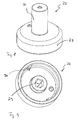
- a socket 22 for the discharge lamp 10 according to the invention is shown.
- the inside view of the base according to Fig. 8 (ie view from the base member 23 inwards) is with Fig. 9 shown.
- the base 22 is formed here as a rotationally symmetrical part and has two recesses to receive the contact pins 50, 51 and to lead the leads 52, 53a in the lamp interior.
- the push contact pin (first contact pin) 50 is placed on the cap member 24 while the side contact pin (second contact pin) 51 is positioned on the base member 23.
- Socket 22 and reflector 20 are hermetically connected.
- the receiving area 29 is formed as a bore and allows centered with respect to the reflector 20 storage of the burner 40 by means of Quetschdichtungen (at least with the aid of the proximal pinch seal). This is necessary to achieve the most efficient light emission.
- an anti-rotation 90 is provided, so that the base remains on the reflector or the outer bulb in its position.
- the receiving region 29 is designed such that both pinch seals with a round, in particular oval or circular cross section and with a rectangular or square cross section can be accommodated.
- Fig. 10 shows a discharge lamp 10 'as known in the art. Shown here are the side by side on a plane with respect to the easy axis arranged contact pins 50 ', 51'. Further, the tubular cover 60 'extending through the entire length of the lamp is shown. In this embodiment, the creepage paths are designed unfavorable for the current.
Landscapes
- Common Detailed Techniques For Electron Tubes Or Discharge Tubes (AREA)
- Pyrane Compounds (AREA)
- Fastening Of Light Sources Or Lamp Holders (AREA)
- Connecting Device With Holders (AREA)
Priority Applications (4)
| Application Number | Priority Date | Filing Date | Title |
|---|---|---|---|
| EP07111394A EP2009668B1 (fr) | 2007-06-29 | 2007-06-29 | Lampe à décharge avec culot unique |
| DE502007002679T DE502007002679D1 (de) | 2007-06-29 | 2007-06-29 | Einseitig gesockelte Entladungslampe |
| AT07111394T ATE456152T1 (de) | 2007-06-29 | 2007-06-29 | Einseitig gesockelte entladungslampe |
| DE202008001737U DE202008001737U1 (de) | 2007-06-29 | 2008-02-08 | Einseitig gesockelte Entladungslampe |
Applications Claiming Priority (1)
| Application Number | Priority Date | Filing Date | Title |
|---|---|---|---|
| EP07111394A EP2009668B1 (fr) | 2007-06-29 | 2007-06-29 | Lampe à décharge avec culot unique |
Publications (2)
| Publication Number | Publication Date |
|---|---|
| EP2009668A1 true EP2009668A1 (fr) | 2008-12-31 |
| EP2009668B1 EP2009668B1 (fr) | 2010-01-20 |
Family
ID=38705083
Family Applications (1)
| Application Number | Title | Priority Date | Filing Date |
|---|---|---|---|
| EP07111394A Not-in-force EP2009668B1 (fr) | 2007-06-29 | 2007-06-29 | Lampe à décharge avec culot unique |
Country Status (3)
| Country | Link |
|---|---|
| EP (1) | EP2009668B1 (fr) |
| AT (1) | ATE456152T1 (fr) |
| DE (2) | DE502007002679D1 (fr) |
Cited By (2)
| Publication number | Priority date | Publication date | Assignee | Title |
|---|---|---|---|---|
| WO2009013699A3 (fr) * | 2007-07-20 | 2009-04-02 | Philips Intellectual Property | Lampe |
| EP2439765A3 (fr) * | 2010-10-11 | 2013-05-01 | General Electric Company | Lampe à décharge pouvue d'une enveloppe, ayant une résistance élevée aux courants de fuite |
Citations (8)
| Publication number | Priority date | Publication date | Assignee | Title |
|---|---|---|---|---|
| EP0321866A2 (fr) * | 1987-12-22 | 1989-06-28 | Patent-Treuhand-Gesellschaft für elektrische Glühlampen mbH | Lampe à d'echarge à haute pression |
| EP0580013A1 (fr) * | 1992-07-17 | 1994-01-26 | Patent-Treuhand-Gesellschaft für elektrische Glühlampen mbH | Lampe à décharge haute pression à culotage d'un seul côté |
| EP0560936B1 (fr) * | 1990-12-06 | 1996-03-27 | Flowil International Lighting (Holding) B.V. | Ensemble lampe a reflecteur comportant un tube a arc a halogene-metal |
| DE19709928A1 (de) * | 1997-03-11 | 1998-09-17 | Patent Treuhand Ges Fuer Elektrische Gluehlampen Mbh | Halogenglühlampe und Fassung |
| EP1052447A2 (fr) * | 1999-05-14 | 2000-11-15 | Stanley Electric Co., Ltd. | Dispositif d' éclairage à décharge pour véhicules |
| EP1383159A2 (fr) * | 2002-07-19 | 2004-01-21 | SLI Lichtsysteme GmbH | Lampe à reflecteur |
| DE102004037381A1 (de) * | 2004-08-02 | 2006-03-16 | Patent-Treuhand-Gesellschaft für elektrische Glühlampen mbH | Kittlos gesockelte Lampe |
| US20060076870A1 (en) * | 2003-02-26 | 2006-04-13 | Ushio Denki Kabushiki Kaisha | Discharge lamp, discharge lamp socket, discharge lamp device, and discharge lamp lighting device |
-
2007
- 2007-06-29 AT AT07111394T patent/ATE456152T1/de active
- 2007-06-29 DE DE502007002679T patent/DE502007002679D1/de active Active
- 2007-06-29 EP EP07111394A patent/EP2009668B1/fr not_active Not-in-force
-
2008
- 2008-02-08 DE DE202008001737U patent/DE202008001737U1/de not_active Expired - Lifetime
Patent Citations (8)
| Publication number | Priority date | Publication date | Assignee | Title |
|---|---|---|---|---|
| EP0321866A2 (fr) * | 1987-12-22 | 1989-06-28 | Patent-Treuhand-Gesellschaft für elektrische Glühlampen mbH | Lampe à d'echarge à haute pression |
| EP0560936B1 (fr) * | 1990-12-06 | 1996-03-27 | Flowil International Lighting (Holding) B.V. | Ensemble lampe a reflecteur comportant un tube a arc a halogene-metal |
| EP0580013A1 (fr) * | 1992-07-17 | 1994-01-26 | Patent-Treuhand-Gesellschaft für elektrische Glühlampen mbH | Lampe à décharge haute pression à culotage d'un seul côté |
| DE19709928A1 (de) * | 1997-03-11 | 1998-09-17 | Patent Treuhand Ges Fuer Elektrische Gluehlampen Mbh | Halogenglühlampe und Fassung |
| EP1052447A2 (fr) * | 1999-05-14 | 2000-11-15 | Stanley Electric Co., Ltd. | Dispositif d' éclairage à décharge pour véhicules |
| EP1383159A2 (fr) * | 2002-07-19 | 2004-01-21 | SLI Lichtsysteme GmbH | Lampe à reflecteur |
| US20060076870A1 (en) * | 2003-02-26 | 2006-04-13 | Ushio Denki Kabushiki Kaisha | Discharge lamp, discharge lamp socket, discharge lamp device, and discharge lamp lighting device |
| DE102004037381A1 (de) * | 2004-08-02 | 2006-03-16 | Patent-Treuhand-Gesellschaft für elektrische Glühlampen mbH | Kittlos gesockelte Lampe |
Cited By (2)
| Publication number | Priority date | Publication date | Assignee | Title |
|---|---|---|---|---|
| WO2009013699A3 (fr) * | 2007-07-20 | 2009-04-02 | Philips Intellectual Property | Lampe |
| EP2439765A3 (fr) * | 2010-10-11 | 2013-05-01 | General Electric Company | Lampe à décharge pouvue d'une enveloppe, ayant une résistance élevée aux courants de fuite |
Also Published As
| Publication number | Publication date |
|---|---|
| DE502007002679D1 (de) | 2010-03-11 |
| ATE456152T1 (de) | 2010-02-15 |
| EP2009668B1 (fr) | 2010-01-20 |
| DE202008001737U1 (de) | 2008-04-03 |
Similar Documents
| Publication | Publication Date | Title |
|---|---|---|
| DE3121077C2 (fr) | ||
| EP1542256B1 (fr) | Dispositif de fixation pour une ampoule de lampe et lampe pourvue d'un tel dispositif | |
| DE19856602B4 (de) | Elektrische Entladungslampeneinrichtung | |
| DE2641867A1 (de) | Elektrische entladungslampe | |
| EP0321866B1 (fr) | Lampe à d'echarge à haute pression | |
| EP1506567B1 (fr) | Lampe a decharge a barriere dielectrique comprenant un socle | |
| WO2010124904A1 (fr) | Lampe à décharge | |
| EP2009668B1 (fr) | Lampe à décharge avec culot unique | |
| EP1334510B1 (fr) | Lampe a decharge a barriere dielectrique | |
| DE10331510B4 (de) | Kurzbogen-Entladungslampe sowie Lichtquellenvorrichtung | |
| WO2009156251A2 (fr) | Lampe électrique comprenant une ampoule extérieure et une lampe encastrée | |
| DE19722601A1 (de) | Halterungsfeder und Anschlagvorrichtung für Lampenbefestigung | |
| DE19701195A1 (de) | Kompakte Niederdruckentladungslampe | |
| DE60320133T2 (de) | Leuchteinheit | |
| DE10133326A1 (de) | Dielektrische Barrieren-Entladungslampe mit Zündhilfe | |
| EP0321867B1 (fr) | Lampe à décharge à haute pression | |
| DE19712776A1 (de) | Hochdruckentladungslampe | |
| EP1138057A1 (fr) | Lampe a decharge haute pression | |
| EP2510537B1 (fr) | Lampe à incandescence halogène pour phare de véhicule | |
| DE69007645T2 (de) | Hochdruckgasentladungslampe. | |
| EP1383159B1 (fr) | Lampe à reflecteur | |
| WO2008135084A1 (fr) | Lampe à décharge à haute intensité avec aide à l'allumage | |
| DE69602581T2 (de) | Gesockelte elektrische lampe | |
| EP0588201A2 (fr) | Lampe à décharge haute pression et procédé pour la fabrication d'une lampe à décharge à haute pression | |
| DE10312720A1 (de) | Dielektrische Barriere-Entladungslampe mit Quetschdichtung |
Legal Events
| Date | Code | Title | Description |
|---|---|---|---|
| PUAI | Public reference made under article 153(3) epc to a published international application that has entered the european phase |
Free format text: ORIGINAL CODE: 0009012 |
|
| 17P | Request for examination filed |
Effective date: 20080429 |
|
| AK | Designated contracting states |
Kind code of ref document: A1 Designated state(s): AT BE BG CH CY CZ DE DK EE ES FI FR GB GR HU IE IS IT LI LT LU LV MC MT NL PL PT RO SE SI SK TR |
|
| AX | Request for extension of the european patent |
Extension state: AL BA HR MK RS |
|
| GRAP | Despatch of communication of intention to grant a patent |
Free format text: ORIGINAL CODE: EPIDOSNIGR1 |
|
| AKX | Designation fees paid |
Designated state(s): AT BE BG CH CY CZ DE DK EE ES FI FR GB GR HU IE IS IT LI LT LU LV MC MT NL PL PT RO SE SI SK TR |
|
| GRAS | Grant fee paid |
Free format text: ORIGINAL CODE: EPIDOSNIGR3 |
|
| GRAA | (expected) grant |
Free format text: ORIGINAL CODE: 0009210 |
|
| AK | Designated contracting states |
Kind code of ref document: B1 Designated state(s): AT BE BG CH CY CZ DE DK EE ES FI FR GB GR HU IE IS IT LI LT LU LV MC MT NL PL PT RO SE SI SK TR |
|
| REG | Reference to a national code |
Ref country code: GB Ref legal event code: FG4D Free format text: NOT ENGLISH |
|
| REG | Reference to a national code |
Ref country code: CH Ref legal event code: EP |
|
| REG | Reference to a national code |
Ref country code: IE Ref legal event code: FG4D |
|
| REF | Corresponds to: |
Ref document number: 502007002679 Country of ref document: DE Date of ref document: 20100311 Kind code of ref document: P |
|
| LTIE | Lt: invalidation of european patent or patent extension |
Effective date: 20100120 |
|
| PG25 | Lapsed in a contracting state [announced via postgrant information from national office to epo] |
Ref country code: PT Free format text: LAPSE BECAUSE OF FAILURE TO SUBMIT A TRANSLATION OF THE DESCRIPTION OR TO PAY THE FEE WITHIN THE PRESCRIBED TIME-LIMIT Effective date: 20100520 Ref country code: LT Free format text: LAPSE BECAUSE OF FAILURE TO SUBMIT A TRANSLATION OF THE DESCRIPTION OR TO PAY THE FEE WITHIN THE PRESCRIBED TIME-LIMIT Effective date: 20100120 Ref country code: ES Free format text: LAPSE BECAUSE OF FAILURE TO SUBMIT A TRANSLATION OF THE DESCRIPTION OR TO PAY THE FEE WITHIN THE PRESCRIBED TIME-LIMIT Effective date: 20100501 Ref country code: IS Free format text: LAPSE BECAUSE OF FAILURE TO SUBMIT A TRANSLATION OF THE DESCRIPTION OR TO PAY THE FEE WITHIN THE PRESCRIBED TIME-LIMIT Effective date: 20100520 |
|
| REG | Reference to a national code |
Ref country code: IE Ref legal event code: FD4D |
|
| PG25 | Lapsed in a contracting state [announced via postgrant information from national office to epo] |
Ref country code: SI Free format text: LAPSE BECAUSE OF FAILURE TO SUBMIT A TRANSLATION OF THE DESCRIPTION OR TO PAY THE FEE WITHIN THE PRESCRIBED TIME-LIMIT Effective date: 20100120 Ref country code: PL Free format text: LAPSE BECAUSE OF FAILURE TO SUBMIT A TRANSLATION OF THE DESCRIPTION OR TO PAY THE FEE WITHIN THE PRESCRIBED TIME-LIMIT Effective date: 20100120 Ref country code: LV Free format text: LAPSE BECAUSE OF FAILURE TO SUBMIT A TRANSLATION OF THE DESCRIPTION OR TO PAY THE FEE WITHIN THE PRESCRIBED TIME-LIMIT Effective date: 20100120 Ref country code: FI Free format text: LAPSE BECAUSE OF FAILURE TO SUBMIT A TRANSLATION OF THE DESCRIPTION OR TO PAY THE FEE WITHIN THE PRESCRIBED TIME-LIMIT Effective date: 20100120 |
|
| PG25 | Lapsed in a contracting state [announced via postgrant information from national office to epo] |
Ref country code: CY Free format text: LAPSE BECAUSE OF FAILURE TO SUBMIT A TRANSLATION OF THE DESCRIPTION OR TO PAY THE FEE WITHIN THE PRESCRIBED TIME-LIMIT Effective date: 20100120 Ref country code: EE Free format text: LAPSE BECAUSE OF FAILURE TO SUBMIT A TRANSLATION OF THE DESCRIPTION OR TO PAY THE FEE WITHIN THE PRESCRIBED TIME-LIMIT Effective date: 20100120 Ref country code: GR Free format text: LAPSE BECAUSE OF FAILURE TO SUBMIT A TRANSLATION OF THE DESCRIPTION OR TO PAY THE FEE WITHIN THE PRESCRIBED TIME-LIMIT Effective date: 20100421 Ref country code: IE Free format text: LAPSE BECAUSE OF FAILURE TO SUBMIT A TRANSLATION OF THE DESCRIPTION OR TO PAY THE FEE WITHIN THE PRESCRIBED TIME-LIMIT Effective date: 20100120 Ref country code: RO Free format text: LAPSE BECAUSE OF FAILURE TO SUBMIT A TRANSLATION OF THE DESCRIPTION OR TO PAY THE FEE WITHIN THE PRESCRIBED TIME-LIMIT Effective date: 20100120 Ref country code: SE Free format text: LAPSE BECAUSE OF FAILURE TO SUBMIT A TRANSLATION OF THE DESCRIPTION OR TO PAY THE FEE WITHIN THE PRESCRIBED TIME-LIMIT Effective date: 20100120 |
|
| PLBE | No opposition filed within time limit |
Free format text: ORIGINAL CODE: 0009261 |
|
| STAA | Information on the status of an ep patent application or granted ep patent |
Free format text: STATUS: NO OPPOSITION FILED WITHIN TIME LIMIT |
|
| PG25 | Lapsed in a contracting state [announced via postgrant information from national office to epo] |
Ref country code: SK Free format text: LAPSE BECAUSE OF FAILURE TO SUBMIT A TRANSLATION OF THE DESCRIPTION OR TO PAY THE FEE WITHIN THE PRESCRIBED TIME-LIMIT Effective date: 20100120 Ref country code: BG Free format text: LAPSE BECAUSE OF FAILURE TO SUBMIT A TRANSLATION OF THE DESCRIPTION OR TO PAY THE FEE WITHIN THE PRESCRIBED TIME-LIMIT Effective date: 20100420 Ref country code: CZ Free format text: LAPSE BECAUSE OF FAILURE TO SUBMIT A TRANSLATION OF THE DESCRIPTION OR TO PAY THE FEE WITHIN THE PRESCRIBED TIME-LIMIT Effective date: 20100120 |
|
| 26N | No opposition filed |
Effective date: 20101021 |
|
| PG25 | Lapsed in a contracting state [announced via postgrant information from national office to epo] |
Ref country code: DK Free format text: LAPSE BECAUSE OF FAILURE TO SUBMIT A TRANSLATION OF THE DESCRIPTION OR TO PAY THE FEE WITHIN THE PRESCRIBED TIME-LIMIT Effective date: 20100120 Ref country code: MC Free format text: LAPSE BECAUSE OF NON-PAYMENT OF DUE FEES Effective date: 20100630 |
|
| PG25 | Lapsed in a contracting state [announced via postgrant information from national office to epo] |
Ref country code: IT Free format text: LAPSE BECAUSE OF FAILURE TO SUBMIT A TRANSLATION OF THE DESCRIPTION OR TO PAY THE FEE WITHIN THE PRESCRIBED TIME-LIMIT Effective date: 20100120 |
|
| PG25 | Lapsed in a contracting state [announced via postgrant information from national office to epo] |
Ref country code: MT Free format text: LAPSE BECAUSE OF FAILURE TO SUBMIT A TRANSLATION OF THE DESCRIPTION OR TO PAY THE FEE WITHIN THE PRESCRIBED TIME-LIMIT Effective date: 20100120 |
|
| PGFP | Annual fee paid to national office [announced via postgrant information from national office to epo] |
Ref country code: FR Payment date: 20110629 Year of fee payment: 5 |
|
| PGFP | Annual fee paid to national office [announced via postgrant information from national office to epo] |
Ref country code: NL Payment date: 20110630 Year of fee payment: 5 Ref country code: GB Payment date: 20110628 Year of fee payment: 5 |
|
| PGFP | Annual fee paid to national office [announced via postgrant information from national office to epo] |
Ref country code: BE Payment date: 20110627 Year of fee payment: 5 |
|
| PGFP | Annual fee paid to national office [announced via postgrant information from national office to epo] |
Ref country code: DE Payment date: 20110629 Year of fee payment: 5 |
|
| REG | Reference to a national code |
Ref country code: CH Ref legal event code: PL |
|
| PG25 | Lapsed in a contracting state [announced via postgrant information from national office to epo] |
Ref country code: CH Free format text: LAPSE BECAUSE OF NON-PAYMENT OF DUE FEES Effective date: 20110630 Ref country code: LI Free format text: LAPSE BECAUSE OF NON-PAYMENT OF DUE FEES Effective date: 20110630 |
|
| PG25 | Lapsed in a contracting state [announced via postgrant information from national office to epo] |
Ref country code: LU Free format text: LAPSE BECAUSE OF NON-PAYMENT OF DUE FEES Effective date: 20100629 Ref country code: HU Free format text: LAPSE BECAUSE OF FAILURE TO SUBMIT A TRANSLATION OF THE DESCRIPTION OR TO PAY THE FEE WITHIN THE PRESCRIBED TIME-LIMIT Effective date: 20100721 |
|
| PG25 | Lapsed in a contracting state [announced via postgrant information from national office to epo] |
Ref country code: TR Free format text: LAPSE BECAUSE OF FAILURE TO SUBMIT A TRANSLATION OF THE DESCRIPTION OR TO PAY THE FEE WITHIN THE PRESCRIBED TIME-LIMIT Effective date: 20100120 |
|
| BERE | Be: lapsed |
Owner name: FLOWIL INTERNATIONAL LIGHTING (HOLDING) B.V. Effective date: 20120630 |
|
| REG | Reference to a national code |
Ref country code: NL Ref legal event code: V1 Effective date: 20130101 |
|
| GBPC | Gb: european patent ceased through non-payment of renewal fee |
Effective date: 20120629 |
|
| REG | Reference to a national code |
Ref country code: FR Ref legal event code: ST Effective date: 20130228 |
|
| REG | Reference to a national code |
Ref country code: DE Ref legal event code: R119 Ref document number: 502007002679 Country of ref document: DE Effective date: 20130101 |
|
| PG25 | Lapsed in a contracting state [announced via postgrant information from national office to epo] |
Ref country code: FR Free format text: LAPSE BECAUSE OF NON-PAYMENT OF DUE FEES Effective date: 20120702 Ref country code: NL Free format text: LAPSE BECAUSE OF NON-PAYMENT OF DUE FEES Effective date: 20130101 Ref country code: BE Free format text: LAPSE BECAUSE OF NON-PAYMENT OF DUE FEES Effective date: 20120630 Ref country code: GB Free format text: LAPSE BECAUSE OF NON-PAYMENT OF DUE FEES Effective date: 20120629 Ref country code: DE Free format text: LAPSE BECAUSE OF NON-PAYMENT OF DUE FEES Effective date: 20130101 |
|
| REG | Reference to a national code |
Ref country code: AT Ref legal event code: MM01 Ref document number: 456152 Country of ref document: AT Kind code of ref document: T Effective date: 20120629 |
|
| PG25 | Lapsed in a contracting state [announced via postgrant information from national office to epo] |
Ref country code: AT Free format text: LAPSE BECAUSE OF NON-PAYMENT OF DUE FEES Effective date: 20120629 |